Sign In
Upload
Manuals
Brands
Bosch Manuals
Keypad
D7412G
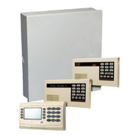
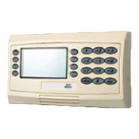
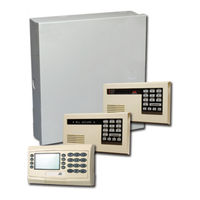
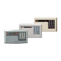
Bosch D7412G Manuals
Manuals and User Guides for Bosch D7412G. We have
4
Bosch D7412G manuals available for free PDF download: Program Entry Manual, Operations & Installation Manual, Installation & Troubleshooting Quick Reference Manual, Installation Manual
Bosch D7412G Program Entry Manual (142 pages)
Brand:
Bosch
| Category:
Control Panel
| Size: 6.38 MB
Table of Contents
Table of Contents
3
Table 1: Literature Referenced
5
Table 2: Differences between the D9412G and D7412G
5
1.0 Introduction
5
Differences between the D9412G and D7412G
5
How to Use this Program Entry Guide
5
Literature Referenced
5
New Features
6
Table 3: New Features
6
Product Handlers
8
Programming Options
8
Table 4: Product Handlers
8
Programming the Control Panel with the D5200 Programmer
9
Table 5: Programming Error Displays
9
Phone 3
11
Phone 4
11
Phone 2
11
Phone 1
11
2.0 9000Main
11
Phone Parameters
12
Modem Format
12
Point/User Flag
12
Table 6: Modem Iiia
13
Table 7: Modem Iiia
13
Table 8: Zones
13
DTMF Dialing
13
Phone Supv Time
14
Alarm on Fail
14
Buzz on Fail
14
Two Phone Lines
14
BFSK Duress Code
15
Ground Start
15
Expand Test Rpt
15
Route Number Groups: Which Has the Highest Priority
15
Called Party Disconnect
15
Routing
15
Routing Destination Communication Failures
16
Dialing Attempts
16
Message Prioritization Within a Route Number
16
Programming a Primary and Backup
16
Programming a Duplicate Report
16
Destination
16
Enhanced Routing
16
Route
17
R# Primary Device
17
R# Backup Device
17
View Events
17
Fire Reports
18
Burglar Reports
18
Table 10: Burglar Reports
18
Table 9: Diagnostic Reports
18
Table 11: User Reports
19
User Reports
19
Diag Reports
20
Test Reports
20
Table 12: Test Reports
20
Table 13: Diagnostic Reports
21
Table 14: Relay Reports
21
Relay Reports
21
Autofunc Reports
21
Table 15: Auto-Function Reports
21
Table 16: RAM Reports
22
Table 17: Point Reports
22
RAM Reports
22
Point Reports
22
Table 19: Access Reports
23
Access Reports
23
User Chng Reports
23
Destination
23
Table 18: User Change Reports
23
Programming a Primary and Backup
23
Enhanced Routing
23
Programming a Duplicate Report
24
RG# Primary SDI
24
RG# Backup SDI
24
Figure 1: Pager Display Fields
25
RG# Primary Pager
25
Table 20: Event Descriptions, Priorities, and Numbers
26
Power Supervision
27
AC Fail Time
27
AC Fail/Res Rpt
28
AC Tag Along
28
P## Supervised
29
Printer Address
29
Bat Fail/Res Rpt
29
Ac/Battery Buzz
29
Printer Parameters
29
P## Scope
30
P## A1 [Through A8] in Scope
30
P## Fire Events
30
P## Burglar Event
30
P## Access Event
30
P## User Event
30
P## Test Event
30
P## Diag Event
30
P## RAM Event
31
P## Usr Chng Evt
31
P## Point Event
31
P## Relay Event
31
P## Auto Functions Event
31
Log Threshold Reports
31
Uploading and Downloading Reports
31
RAM Parameters
31
RAM Callback Reports
31
RAM Passcode
32
Log % Full
32
RAM Call Back
32
RAM Line Monitor
32
Answer Armed
33
Answer Disarmed
33
Ram Ph
33
Cancel Report
34
Area
34
A# Area on
34
Duress Type
34
Miscellaneous
34
Area Parameters
34
Programming Account Numbers in 9000 Series Control Panels, Versions 6.20 and Higher
35
Table 21: Programming Four Digit Account Numbers
35
Table 22: Programming Ten Digit Account Numbers
35
A# Exit Tone
36
A# Exit Dly Time
36
A# Delay Res
36
A# FA Bypass Max
36
Figure 2: Account Number Entry
36
Table 23:Verify Time
37
A# Auto Watch
37
A# Verify Time
37
A# Duress Enable
38
A# Area Type
39
Shared-Area Characteristics
40
Bell Parameters
40
Area
40
A# Single Ring
41
A# Burg Pat
41
A# Burg Time
41
A# Fire Time
41
A# Fire Pat
41
Open/Close Options
42
A# Bell Test
42
Area
43
A# Acct O/C
43
A# Area O/C
44
A# Disable O/C in Window
44
A# Auto Close
44
A# Fail to Open
44
A# Fail to Close
45
A# Restrictd O/C
45
CMD Center
46
A# Perimeter O/C
46
Command Center
46
2.10.1 CMD Cntr (Command Center) Assignment
46
CC# Supervised
47
CC# Area Assign
47
CC# Scope
47
CC# A1[Through A8] in Scope
48
CC# Entr Key Rly
48
CC# Entr Cycl Dr
48
CC# Assign Door
49
CC# Trouble Tone
49
CC# Entry Tone
49
CC# Exit Tone
49
Area
50
Area # Not Ready
50
Area# Is on
50
Area # Is off
50
CC# Enhanccmdctr
50
CC# Arm Now Warn
50
2.10.2 Area Text
50
CC# Close Door
50
Custom Function
51
Area # Acct Is on
51
CF### Text
51
Table 24: CF### Custom Function Keystrokes
52
CF### Key Strokes
52
User Interface
53
2.11.1 Commands
53
2.11.2 Command Center Selections
53
Table 25: Command Center Programming Choices
53
Perim Delay
54
Watch Mode
54
Perim Partial
54
Perim Instant
54
Master Arm Delay
54
Mstr Arm Inst
54
View Area Stat
55
View Memory
55
View Pt Status
55
Walk Test
55
Fire Test
55
Send Report
55
Door Control
55
Del User
56
View Log
56
Extend Close
56
Access Ctl Level
56
Add User
56
Chg Passcode
56
Chg Time/Date
56
Chg Display
56
Remote Program
57
Change Relay
57
Reset Sensors
57
Bypass a Pt
57
Unbypass a Pt
57
User CMD 7
57
Print Log
57
User CMD 9
57
Default Text
58
Change Skeds
58
C Function 128 [Through 143]
58
Service Walk
58
Display Rev
58
Move to Area
58
2.11.3 Authority Level Selections
59
Table 26: Authority Level Selections
59
Authority Level
59
L## Disarm
59
L## Master Arm Delay
59
L## Mstr Arm Inst
59
L## View Memory
60
L## Walk Test
60
L## View Pt Status
60
L## Watch Mode
60
L## View Area Stat
60
L## Perim Partial
60
L## Perim Delay
60
L## Perim Instant
60
L## Fire Test
61
L## Send Report
61
L## Door Control
61
L## Cycle Door
61
Table 27: L## Secure Door-Door Mode Definitions
62
L## Unlock Door
62
L## Secure Door
62
L## Access Ctl Lvl
62
L## Extend Close
63
L## User CMD 7
63
L## Print Log
63
L## View Log
63
L## Chg Passcode
63
L## del User
63
L## Chg Time/Date
63
L## Chg Display
63
L## Add User
63
L## Remote Program
64
L## Service Walk
64
L## Display Rev
64
L## Move to Area
64
L## Change Relay
64
L## Reset Sensors
64
L## Unbypass a Pt
64
L## Bypass a Pt
64
L## User CMD 9
64
L## Restricted O/C
65
L## Passcode Arm
65
L## Send Duress
65
L## Perimeter O/C
65
L## C Function 128 [Through 143]
65
L## Area O/C
65
L## Force Arm
65
L## Change Skeds
65
L## Default Text
65
L## Passcode Disarm
66
L## Security Level
66
L## Disarm Level
66
Function List
67
Relay Parameters
67
Menu Item
67
M## Function
67
M## CC Address 1 [Through 8]
67
A# Alarm Bell
68
Area
68
2.13.1 Area Relays
68
A# Reset Sensors
69
A# Fail to Close
69
A# Force Armed
69
A# Watch Mode
69
A# Fire Bell
69
A# Silent Alarm
70
A# Perim Fault
70
A# Duress Relay
70
A# Area Fault
70
A# Area Armed
70
2.13.2 Panel-Wide Relays
71
AC Failure
71
Battery Trouble
71
Phone Fail
71
Summary Supfire
72
Summary Supburg
72
Summary Trouble
72
Log % Full
72
Summary Fire Tbl
72
Summary Alarm
72
Summary Fire
72
Comm Fail
72
3.0 Radxusr1/Radxusr2
73
Passcode/Token Worksheet
73
User Groups
73
Passcodes
73
User Group Window
73
Authority Level by Area
73
User Name
73
Tokens/Cards
73
Reporting and Logging
73
U### Passcode
74
Table 28: BSFK User Code Report
74
User
74
Figure 3: User Group 122 Example
74
U### User Group
75
U### Area 1 [Through Area 8] Auth
75
U### Name
75
U### Mstr Site
75
U### Mstr C/D
76
U### SU1 through SU3 Site
76
U### SU1 through SU3 C/D
76
4.0 Radxpnts
77
Point Index
77
P## Type
77
Point Responses
81
P## Pt Response
82
P## Ring Til Rst
83
P## Silent Bell
83
P## Ent Tone off
83
P## Entry Delay
83
P## Audible after 2 Failures
84
P## Invisible Pt
84
P## Buzz on Fault
85
P## Watch Point
85
P## Rlyresp Type
86
P## Disp as DVC
86
P## Local While Disarmed
86
P## Local While Armed
86
P## Disable Rst
87
P## FA Retrnable
87
P## BP Retrnable
87
P## Bypassable
88
P## Swinger Byps
88
P## Report Bypass at Occurrence
88
P## Cross Point
89
P## Defer BP Report
89
P## Fire Point
90
Point Assignments
91
P## Alarm Verify
91
P## Resettable
91
Point Number
91
P### Area Assign
92
P### Point Index
92
P### Debounce
92
Table 29: P### Bfsk/Relay Codes/Relays
93
Table 30: Point Text for Points 240 to 247
93
P### Bfsk/Relay
93
P### Point Text
93
CMD9 Point Text
94
CMD9 Bfsk/Relay
94
CMD9 Point Index
94
CMD7 Point Text
94
CMD7 Point Index
94
COMMAND 7 and COMMAND 9
94
CMD7 Bfsk/Relay
94
Table 31: Window Selections
95
Window
95
W# Sunday
95
Opening and Closing
95
Windows
95
Radxsked
95
W# Monday
96
W# Tuesday
96
W# Wednesday
96
W# Thursday
96
W# Friday
96
W# Saturday
96
W# Open Early Begin
96
W# Open Window Start
96
Figure 4: Example Opening Window Timeline (Using Two Opening Windows on same Day)
97
W# Open Window Stop
97
Table 33: Programming to Link Two Days over Midnight
98
W# Close Early Begin
98
Table 32: Programming for Two same Day Opening Windows (See Figure 4)
98
Table 34: W# Close Window Stop Programming Example
99
W# Close Window Start
99
W# Close Window Stop
99
W# Holiday 4
100
W# Area 1 [Through 8]
100
W# Holiday 2
100
W# Holiday 3
100
W# Holiday 1
100
W# Xept Holiday
100
Table 35: Opening/Closing Windows Worksheet
101
Table 36: Opening/Closing Windows
101
Table 37: Normal Store Hours
101
User Windows
102
UW# User Group
102
User Group Windows
102
Table 39: Monthly Auditor's Schedule
102
Table 38: Delivery Schedule
102
UW# Sunday
103
UW# Monday
103
UW# Tuesday
103
UW# Wednesday
103
UW# Thursday
103
UW# Friday
103
UW# Saturday
103
UW# Group Enable
103
UW# Group Disable
103
S## Timeedit
104
Sked Number
104
UW# Holiday 4
104
UW# Holiday 3
104
UW# Holiday 2
104
UW# Xept Holiday
104
Skeds
104
UW# Holiday 1
104
S## Function Code
105
S## Area 1[Through 8]
105
S## Point Number
105
S## Area 1[Through 8]
106
S## Relay Number
106
S## Defer Test
107
S## Hourly Report
107
S## Defer Status
107
S## CMD Center
108
S## Custom Func
108
S## Door 1 [Through 8]
109
S## Access Ctl Level
109
S## CMD Center 1[Through 8]
109
S## Door 1 [Through 8]
110
S## Door 1 [Through 8]
111
S## Time
112
S## Date
112
S## Sunday
112
S## Monday
112
S## Tuesday
112
S## Wednesday
112
S## Thursday
112
S## Friday
112
S## Saturday
112
S## Holiday 2
113
Date
113
S## Holiday 3
113
S## Holiday 4
113
S## Holiday 1
113
Add/Change/Delete
113
Holiday Indexes
113
S## Xept Holiday
113
View Holidays
114
Holiday Index 1
114
Holiday Index 2
114
Holiday Index 3
114
Holiday Index 4
114
Index 1 Days
114
Index 2 Days
114
Index 3 Days
114
Index 4 Days
114
Enable SDI Auto
115
Parity/Stop
115
Baud Rate
115
SDI Automation
115
Requirements
115
Introduction
115
6.0 Radxaux1
115
SDI RAM Parameters
116
9133 Supervision
116
RTS Control
116
DTR Control
116
Status Rate
116
Enable SDI RAM
117
Command 43
117
Figure 5: COMMAND 43 Flow Chart
117
User Interface Modifications for COMMAND
117
Using an External Modem
118
Figure 6: RAM IP Address Prompts
118
Call Back Enabled
118
RAM IP Address 1
118
RAM IP Address 2
118
RAM IP Address 3
118
RAM IP Address 4
118
Figure 7: Com Port Selection Within Hyperterminal
120
Figure 8: External Modem Connection
120
Enable Ext Modem
122
Answer Armed
122
Answer Disarmed
122
RAM Line Monitor
122
Seize Relay
122
Modem Init String
122
RAM Dial String
122
Enhanced Communications
122
Path # IP Add2
123
Path # Poll Rate
123
Path # IP Add3
123
Path # IP Add4
123
Path # IP Add1
123
Enhanced Comm
123
Figure 9: Path # IP Add1 to Add4
123
Programming Path Numbers and IP Addresses
123
Programming Path Numbers and IP Addresses123
123
Figure 10: Poll Rate Timeline
124
SDI Ram/Enhanced Communications
125
Baud Rate
125
Configuration
125
Path # Retry Count
125
Path # Ack Wait
125
SDI Ram/Enhanced Communications Configuration
125
Route Group Attempts
126
Parity/Stop
126
RTS Control
126
DTR Control
126
9133 Supervision
126
Base Port Number
126
Fire Trouble Resound
127
Enable Anti Replay
127
Fire Supv Res Type
127
Enable Protocol Type
127
Miscellaneous
127
RG# 1 Attempt
127
Cross Point Parameters
128
Table 40: Cross Point Ranges Within Groups
128
Cross Point Time
129
D#CC#Scope
131
D# Door Point
131
D# Entry Area
131
Door
131
Door Profile
131
7.0 Radxaxs
131
D# Interlock Point
132
D# Auto Door
132
D# Fire Unlock
132
D# Disarm on Open
132
D# Shunt Time
133
D# Extend Time
133
D# Buzz Time
133
Strike Profile
133
D# Strike Time
133
Door
133
D# Card Type
133
Event Profile
134
D# Deact on Open
134
D# RTE Shunt Only
134
D# Rexshunt Only
134
Door
134
D# Access Granted
135
D# no Entry
135
D# Enter Request
135
D# Exit Request
135
Programming Prompts
136
Programming Prompts Directory
136
Advertisement
Bosch D7412G Operations & Installation Manual (76 pages)
Brand:
Bosch
| Category:
Control Panel
| Size: 2.68 MB
Table of Contents
Table of Contents
3
1 0 Introduction
7
Document Organization
7
Related Documentation
7
Table 1: Manual Organization
7
Documentation Conventions
8
Type Styles Used in the Text
8
Tips, Notes, Cautions, and Warnings
8
Table 2: Related Documentation
8
Table 3: Text Type Styles
8
FCC Rules
9
Part 15
9
Part 68
9
2 Overview
11
9000G Series Panel Differences
11
Figure 1: System Configuration
11
Table 4: 9000G Series Panel Differences
11
Specifications
12
Table 5: Specifications
12
Compatible Accessories
13
New Features in D9412G/D7412G
13
Introduction
13
Ground Fault Detect
13
Added Feature When Using Ground Fault Detect
13
Table 6: Compatible Accessories
13
Netcom Functionality
14
Standard Features
14
Points
14
Areas and Accounts
14
Communicator
14
Command Centers
14
Table 7: Compatible Command Centers
14
Keyswitch
15
Access Control
15
Event Memory
15
Event Log
15
EMI and Lightning Transient Protection
15
Programming
15
Other Features
15
Control Panel Assembly
15
Available by Separate Order
16
Listings and Approvals
16
Table 8: Listings
16
3 Installation
17
Before Beginning
17
Enclosure Options
17
Beginning the Installation
17
Figure 2: Enclosure Mounting
17
Installing the Assembly
18
Connecting Earth Ground
18
Terminal
18
Ground Fault Detect Enable
18
Locking the Reset Pin
18
Figure 3: Ground Fault Detect
18
Finishing the Installation
19
Charge the Battery While Finishing
19
Install and Wire Detection Devices
19
Install Modules and Relays
19
Make the Telephone Connections
19
Connect the On-Board Points and Command Centers
19
Figure 4: Reset Pin
19
Power up
20
Programming the Panel
20
Install the Point Chart Label
20
Testing the System
20
Primary Power Terminals
21
Primary (AC) Power Circuit
21
Installing the Transformer
21
Secondary Power Terminals
21
Secondary (DC) Power
21
Installing the Battery
21
4 0 Power Supply
22
Replacing the Battery
22
Figure 5: Non-Power Limited Wiring
22
Battery Supervision
23
Battery Charging Circuit
23
Battery Discharge/Recharge Schedule
23
Figure 6: Charging and Battery Leds
23
Table 9: Battery Discharge/Recharge Schedule
23
Charging Status and Low Battery Leds
24
Table 10: Charging Status and Low Battery Leds
24
5 Power Outputs
25
Circuit Protection
25
Total Available Power
25
Continuous Power Outputs Terminals
25
Continuous Current Draw
25
Programmable Power Outputs Terminals
25
Programming
25
Optional Relays Required
25
Terminals 6 and 7
26
Fire System Power Formula
26
Terminal 8
26
Figure 7: Relays for Terminals 7, 8, and Ground Start
26
6 Telephone Connections
27
Registration
27
Notification
27
Location
27
Phone Cord Connection
27
Figure 8: RJ31X Wiring
27
Figure 9: Phone Connector, Phone LED, and Operation Monitor LED Locations
27
Phone LED (Red)
28
Operation Monitor LED (Green)
28
Dialing Format
28
Phone Line Monitor
28
Called Party Disconnect
28
Communication Failure
28
Enhanced Communication
28
Ground Start
29
Relay Installation
29
Phone Monitor Select Jumper
29
D928 Dual Phone Line Switcher
29
Description
29
Operation
29
Figure 10: Phone Monitor Select
29
Watchdog Feature
30
Installing the D928
30
Figure 11: D928 Dual Phone Line Switcher
30
D928 Status Leds
31
7 On-Board Points
33
Description Terminals
33
Point Sensor Loops
33
Point Parameters
33
Figure 12: On-Board Point Sensor Loop Wiring
33
Table 11: Point Parameters
33
Point Response Time
34
Wiring Information for Installations Using the
34
Figure 13: Wiring for Installation Using the Ademco AB-12 Bell/Housing
35
8 Off-Board Points
37
Point (ZONEX) Bus D9412G
37
Terminals
37
D7412G Terminals
37
D8125, D8127 and D9127 POPIT Modules
38
Listings
38
Installing the D8125 POPEX Module
38
Mounting
38
Wiring the D8125 to the Control Panel
38
Wiring Popits to the Data Expansion Loop
38
Table 12: Data Expansion Loop Wire Specifications
38
Figure 14: Connecting the D8125 POPEX to the D9412G Panel
39
Figure 15: Connecting the D8125 POPEX to the D7412G Panel
40
Wiring Data Expansion Loops to POPEX Modules
41
POPIT Sensor Loops
41
POPIT Module Point Assignments
41
Program Record Sheet
42
Figure 16: Program Record Sheet
42
D8128D Octopopit Module
43
Description
43
Listings
43
Installation
43
Figure 17: D8128D Octopopit Layout
43
Setting the Octopopit Switches
44
Mounting
44
Table 13: D8128D Octopopit Switch Settings for D8412G/D7412G
44
Wiring Octopopits
45
Figure 18: Connecting D8128D Octopopits to the D9412G
45
Figure 19: Connecting D8128D Octopopits to the D7412G
46
Octopopit Sensor Loops
47
Figure 20: Wiring Multiple D81282Ds Using Molex Connectors
47
Table 14: Terminal Strip Connections
47
Testing Off-Board Points
48
Figure 21: D8128D Octopopit Sensor Loops
48
9 Off-Board Relays
49
D8129 Octorelay
49
Configuring the D8129 Octorelay
49
Relay Outputs
49
Installation
49
Wiring Connections
49
Table 15: D8129 Octorelay Switch Settings
49
Figure 22: D8129 Connections to the D9412G
50
Figure 23: D8129 Connections to the D7412G
50
D811 Arm Status Relay Module
51
Relay Output
51
Installation
51
Wiring Connections
51
Table 16: Number of D8128Ds Used with D8129S
51
Figure 24: D811 Module Wiring to the D7412G
52
Figure 25: D811 Module Wiring to the D9412G
52
10 0 Arming Devices
53
Description
53
Command Center Terminals
53
Assigning the Command Center an Address
53
Installation
53
Table 17: Command Center Address Settings
53
Table 18: Command Center Connections
53
Figure 26: Power at Command Centers
54
D268/D269 Independent Zone Control, D279A Independent Zone Control
55
Keyswitch
55
Description
55
Programming
55
Installation
55
Keyswitch Operation
55
Figure 27: Keyswitch Wiring
55
11 0 SDI Devices
57
Description
57
Installation
57
D9131A Parallel Printer Interface Module
57
Switch Settings
57
Supervision
57
D9210B Wiegand Control Interface Module
57
Table 19: SDI Device Connections
57
Table 20: Printer Address Switch Settings
57
SDI Address 80
58
D9133 Serial Interface Module
58
Address Settings
58
Supervision
58
SDI Address 88
58
D9133DC Direct Connect Programming Module
58
Figure 28: D9133 Jumper Settings
58
Table 21: Access Control Module Address Switch Settings
58
D9133TTL-E Network Interface Module
59
Address Settings
59
Supervision
59
Figure 29: D9133TTL-E Jumper Settings
59
12 Programmer/Accessory Connections
61
Programmer Connector
61
Programmer Access Reports
61
Accessory Connector
61
Figure 30: Reset Pin
61
Figure 31: Programmer and Accessory Connections
61
13 0 Faceplates
63
D9412G Faceplate
63
Figure 32: D9412G Faceplate
63
D7412G Faceplate
64
Figure 33: D7412G Faceplate
64
System Wiring Diagrams, Issue a
65
D9412G Control Panel, 1 of 3
65
Figure 34: D9412G System Wiring Diagram, 1 of 3
65
Appendix A
65
D9412G Control Panel, 2 of 3
66
Figure 35: D9412G System Wiring Diagram, 2 of 3
66
D9412G Control Panel, 2 of 3
67
Figure 36: D9412G System Wiring Diagram, 3 of 3
67
D7412G Control Panel, 1 of 3
68
Figure 37: D7412G System Wiring Diagram, 1 of 3
68
D7412G Control Panel, 2 of 3
69
Figure 38: D7412G System Wiring Diagram, 2 of 3
69
D7412G Control Panel, 3 of 3
70
Figure 39: D7412G System Wiring Diagram, 3 of 3
70
Point Address Charts
71
ZONEX 1, Points 9 to 127 (D9412G); ZONEX 1, Points 9 to 75 (D7412G)
71
Table 22: ZONEX 1 Point Address Chart
71
Appendix B
71
ZONEX 2, Points 129 to 247 (D9412G Only)
72
Table 23: ZONEX 2 Point Address Chart
72
Index
73
Bosch D7412G Installation & Troubleshooting Quick Reference Manual (32 pages)
Brand:
Bosch
| Category:
Control Panel
| Size: 0.56 MB
Table of Contents
Table of Contents
3
D9412G Control Panel, 2
4
1 Introduction
5
Manual Organization
5
D9412G Control Panel, 3
5
Table 1: Chapter Summary
5
Other Literature Referenced
6
Table 2: Referenced Literature
6
2 Quick Reference Terminal Description
7
Table 3: Quick Reference Terminal Description
7
3 Troubleshooting
9
Introduction
9
Problems Found During Self Diagnostics
9
Table 4: Troubleshooting Problems Found During Self Diagnostics
9
Problems Programming the Panel
10
Table 5: Troubleshooting Problems Programming the Panel
10
Problems with Command Centers
11
Phone Line Trouble
11
Table 6: Troubleshooting Command Center Problems
11
Table 7: Troubleshooting Phone Line Problems
11
Communication Failure
12
Table 8: Troubleshooting Communication Failures
12
Problems with Points
13
Table 9: Troubleshooting Problems with Points
13
Extra Points
14
Problems with the D8125 POPEX Data Expansion Loops
15
Metering the Loops
15
Table 10: Data Expansion Loop Wire Specifications
15
EMI on Long Wire Runs
16
Checking Shielded Cable
16
Battery and Power Reports
16
Watchdog Reset Reports
17
Runaway Reports to the Receiver
17
Overloaded Power Supply
17
Service Walk Test
18
Figure 1: Service Walk Test Flow Chart
19
Ground Fault
20
Procedure for Isolating Earth Ground Faults
20
Table 11: Terminal Grouping Ground Fault
20
Panel Buzzer
21
4 System Wiring Diagrams, Issue a
23
Figure 2: D9412G System Wiring Diagram
23
Figure 3: D9412G System Wiring Diagram
24
Figure 4: D9412G System Wiring Diagram
25
Figure 5: D7412G System Wiring Diagram
26
Figure 6: D7412G System Wiring Diagram
27
Figure 7: D7412G System Wiring Diagram
28
Figure 8: D7212G System Wiring Diagram
29
Figure 9: D7212G System Wiring Diagram
30
Figure 10: D7212G System Wiring Diagram
31
D7212G Control Panel, 3 of 3
31
Advertisement
Bosch D7412G Installation Manual (8 pages)
D720 Series
Brand:
Bosch
| Category:
Keypad
| Size: 0.45 MB
Table of Contents
Function Keys
2
Setting the Keypad Address
4
Control Panel Programming
6
Specifications
7
Advertisement
Related Products
Bosch D720
Bosch D720B
Bosch D720W
Bosch D7212G
Bosch D630
Bosch D626
Bosch D620
Bosch D621B
Bosch D623W
Bosch D625B
Bosch Categories
Dishwasher
Washer
Oven
Power Tool
Dryer
More Bosch Manuals
Login
Sign In
OR
Sign in with Facebook
Sign in with Google
Upload manual
Upload from disk
Upload from URL