User Manuals: Beckhoff C9900-G002 Push-button extension
Manuals and User Guides for Beckhoff C9900-G002 Push-button extension. We have 4 Beckhoff C9900-G002 Push-button extension manuals available for free PDF download: Manual
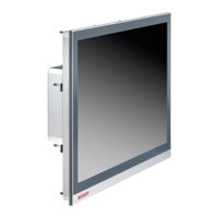
Beckhoff C9900-G002 Manual (55 pages)
Brand: Beckhoff
|
Category: Touch Panel
|
Size: 10 MB
Table of Contents
Advertisement
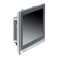
Beckhoff C9900-G002 Manual (53 pages)
Brand: Beckhoff
|
Category: Touch Panel
|
Size: 7 MB
Table of Contents
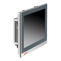
Beckhoff C9900-G002 Manual (52 pages)
Brand: Beckhoff
|
Category: Touch Panel
|
Size: 7 MB
Table of Contents
Advertisement
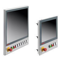
Beckhoff C9900-G002 Manual (45 pages)
Push button extension
Brand: Beckhoff
|
Category: Controller
|
Size: 6 MB