Sign In
Upload
Manuals
Brands
AUMA Manuals
Controller
TIGRON TR-M30X
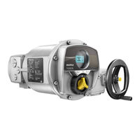
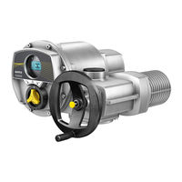
AUMA TIGRON TR-M30X Manuals
Manuals and User Guides for AUMA TIGRON TR-M30X. We have
6
AUMA TIGRON TR-M30X manuals available for free PDF download: Manual, Operation Instructions Manual, Short Instructions
AUMA TIGRON TR-M30X Manual (132 pages)
Multi-turn actuators
Brand:
AUMA
| Category:
Controller
| Size: 4 MB
Table of Contents
Table of Contents
2
Configuration of Analogue Output 1
2
Signal Range of Analogue Output 1
2
Adjustment of Analogue Output 1
2
Safety Instructions
7
Prerequisites for the Safe Handling of the Product
7
Range of Application
8
Warnings and Notes
8
References and Symbols
8
Short Description
10
Operation
12
Menu Navigation
12
Combi-Switch Operation Elements
12
Control Panels Magnetic Pen Operation
13
Device Menu and Status Indications
13
Open Device Menu (Combi-Switch Version)
14
Exit Device Menu / Show Status Indications (Combi-Switch Version)
14
Open Device Menu (Magnetic Pen Control Panel Version)
15
Exit Device Menu / Show Status Indications(Magnet Pen-Control Panel Version)
16
3.1.3.5. Directly Open Menu Page by Entering the ID
16
User, User Level, Password
17
3.1.4.1. Change User Level
17
3.1.4.2. Change Passwords
18
Timeout for Incorrect Password Entry (Security)
19
Language Change in the Display
19
Indications
21
Indications and Symbols in the Display
21
Feedback Signals from Actuator and Valve
22
Status Indications According to AUMA Classification
24
Status Indications According to NAMUR Recommendation
24
Indication Lights of Local Controls
25
Output Signals
27
Signals Via Profibus DP
27
Signals Via Modbus RTU
27
Status Signals Via Output Contacts (Digital Outputs)
27
Configuration of Outputs
27
Output Coding
27
Configurable Status Signals
28
Analogue Signals (Analogue Outputs)
28
Configuration of Analogue Output 1
28
Signal Range of Analogue Output
29
Adjustment of Analogue Output
30
Input Signals
32
Control Via Profibus DP
32
Control Via Modbus RTU
32
Binary Input Signals (Digital Inputs)
32
Operation
34
Operation Mode off
34
Operation Mode LOCAL
34
Push-To-Run Operation or Self-Retaining Local
34
Operation Mode REMOTE
35
Push-To-Run Operation or Self-Retaining Remote
35
Operation Mode EMERGENCY
36
Operation Mode Disabled
36
Commissioning
38
Start Commissioning Assistant
38
Perform Manual Commissioning
38
Type of Seating Setting Via the Device Menu
39
Torque Seating Setting Via the Device Menu
40
Limit Switching Setting Via the Device Menu
41
Test Run
45
Check Direction of Rotation at Hollow Shaft/Stem
45
Check Limit Switching (Combi-Switch Version)
46
Check Limit Switching (Magnetic Pen Control Panel Version)
46
Date and Time
47
Display Formats
48
Date Format
48
Time Format
48
Number Format
48
Torque Unit
48
Temperature Unit
48
Position Units
49
Process Factor Units
49
Analogue Working Value Units (AIN)
50
Analogue Signal Output Units (AOUT)
51
Contrast
52
Application Functions
53
Profibus DP Interface
53
Bus Address (Slave Address)
53
Redundancy
53
Response Telegrams for AUMA Redundancy
53
Connection Type Compatibility with Process Representation
54
Modbus Interface
54
Bus Address (Slave Address)
54
Baud Rate
54
Parity/Stop Bit
54
Monitoring Time
55
Response Timeout
55
Redundancy
55
Response Telegrams for AUMA Redundancy
55
Intermediate Positions
56
Define the Pivot Points of Intermediate Positions
56
Set Signal Behaviour of Intermediate Positions
56
Hysteresis for Intermediate Positions: Set
57
Positioner (Operation Mode REMOTE SETPOINT)
58
Activate Positioner
59
Activate/Deactivate Adaptive Behaviour
59
Set Overrun (Inner Dead Band) Manually
62
Set Max. Error Variable (Outer Dead Band) Manually
63
Set the Dead Time
63
Set Hysteresis for Positioner
63
Closing Fully/Opening Fully (End Position Tolerance for Setpoint)
64
Limit Setting Range
64
Change-Over between OPEN-CLOSE Control and Setpoint Control
65
12.4.10. Input of Setpoint Position: Parallel Interface
65
12.4.11. Input Range of Setpoint Position: Parallel Interface
66
12.4.12. Input of Setpoint Position: Profibus DP
66
12.4.13. Input Range of Setpoint Position: Profibus DP
66
12.4.14. Input of Setpoint Position: Modbus RTU
67
12.4.15. Input Range of Setpoint Position: Modbus RTU
67
Stepping Mode
67
Activate Stepping Mode
68
Operation Mode for Stepping Mode
68
Start and End of Stepping Mode
69
On Times and off Times
69
Additional Inputs for Fieldbus
69
Combination of Fieldbus-Parallel Interface
70
Auto Change-Over I/O (During Fieldbus Failure)
71
Failure Functions
72
Safety Parameters
72
Safety Tripping
72
Set Failure Source (Failure Reason) for a Failure Operation
73
Failure Operation (Reaction of the Actuator) on Loss of Signal
73
Failure Position
74
Safety Delay Setting
74
Emergency Parameters and EMERGENCY Behaviour
75
Activate EMERGENCY Behaviour
76
Emergency Tripping
76
Set Failure Source (Failure Reason) for an EMERGENCY Operation
77
EMERGENCY Operation
77
Emergency Position
78
Set Emergency Delay
78
Operation Mode for EMERGENCY Behaviour
78
Bypass Stepping Mode
78
Bypass Interlock
79
Enabling Local Controls
79
Activate Enabling Function
80
Enabling Function Behaviour
80
Priority REMOTE
80
Activate Priority REMOTE
81
Priority REMOTE Behaviour
81
Fieldbus Auto Enable
82
Interlock (Enabling Operation Commands)
82
Activate Interlock
83
Set Source of the Interlock Enable Signal
83
Operation Mode for Interlock
83
Interlock Behaviour (Running Direction)
84
Partial Valve Stroke Test (PVST)
84
Bluetooth Interface Can be Activated and Deactivated (Security)
85
Monitoring Functions
88
Torque Monitoring
88
Excessive Torque
88
Wedge Plug Valve
90
Motor Protection Monitoring (Thermal Monitoring)
92
Monitoring the Type of Duty (Motor Starts and Running Time)
93
Operating Time Monitoring
94
Motion Detector
96
Activate Motion Detector
96
Detection Time Dt
96
Travel Difference DX
96
Delay Time
96
Monitoring Power Supply of Electronics
97
Temperature Monitoring
97
Monitoring the Heating System/Heater
97
Verification of Sub-Assemblies
98
Phase Failure Monitoring
98
Phase Sequence Detection and Correction of the Direction of Rotation
99
Activate and Enable Functions
100
Activation
100
Enabling
100
Diagnostics
102
Electronic Device ID
102
Diagnostic Bluetooth
102
Diagnostics Interface
103
Diagnostics Position Transmitter MWG
104
Diagnostics Positioner
104
Diagnostics on Time Monitoring
105
Diagnostics Profibus
105
Diagnostics Modbus
105
Simulation (Inspection and Test Function)
106
Actuator Signals
106
Operational Info Collection
107
Operating Data
107
Event Report
108
Characteristics
108
Torque Profile Characteristics
108
Temperature-Time Characteristics
109
Histograms
110
Motor Running Time-Position (Histogram)
110
Motor Running Time-Torque (Histogram)
110
Maintenance (Information and Signals)
111
Display Operating Times
113
Device Temperature Display
113
Corrective Action
114
Fuses
114
Fuses Used
114
Motor Protection (Thermal Monitoring)
114
Fault Indications and Warning Indications
116
Appendix
120
Selection Overview for Output Contacts and Indication Lights (Digital Outputs DOUT)
120
Index
124
Parameter Index
127
Advertisement
AUMA TIGRON TR-M30X Operation Instructions Manual (76 pages)
Multi-turn actuators
Brand:
AUMA
| Category:
Controller
| Size: 2 MB
Table of Contents
Safety Instructions
5
Short Description
8
Transport and Storage
12
Electrical Connection
23
Cable Connection
27
Menu Navigation
34
Signals (Output Signals)
56
Corrective Action
58
Servicing and Maintenance
64
Technical Data
66
Spare Parts
70
AUMA TIGRON TR-M30X Manual (40 pages)
Multi-turn actuators
Brand:
AUMA
| Category:
Controller
| Size: 0 MB
Table of Contents
Safety Instructions
4
General Information about Profibus DP
6
Corrective Action
33
Troubleshooting
33
Technical Data
36
Profibus DP Interface
36
Advertisement
AUMA TIGRON TR-M30X Short Instructions (10 pages)
Multi-turn actuators Modbus RTU
Brand:
AUMA
| Category:
Controller
| Size: 0 MB
Table of Contents
Table of Contents
2
Basic Information on Fieldbus Connection
3
Fieldbus Connection for Line Topology
4
Fieldbus Connection for Loop Topology
6
Set Fieldbus (Slave Address) Via Device Menu
8
Modbus Parameter Overview in Device Menu
9
AUMA TIGRON TR-M30X Short Instructions (8 pages)
Multi-turn actuators Profibus DP
Brand:
AUMA
| Category:
Controller
| Size: 0 MB
Table of Contents
Basic Information on Fieldbus Connection
3
Fieldbus Connection for Line Topology
4
Connection with Support Terminals
5
Set Fieldbus (Slave Address) Via Device Menu
6
Profibus Parameter Overview in Device Menu
7
AUMA TIGRON TR-M30X Short Instructions (8 pages)
Profibus DP Multi-turn actuators
Brand:
AUMA
| Category:
Controller
| Size: 0 MB
Table of Contents
Basic Information on Fieldbus Connection
3
Fieldbus Connection for Line Topology
4
Set Fieldbus Address (Field Device Address) Via the Device Menu
6
Profibus Parameter Overview in Device Menu
7
Advertisement
Related Products
AUMA TIGRON TR-M1000X
AUMA TIGRON TR-M60X
AUMA TIGRON TR-M120X
AUMA TIGRON TR-M250X
AUMA TIGRON TR-M500X
AUMA TIGRON TR-MR30X
AUMA TIGRON TR-MR60X
AUMA TIGRON TR-MR120X
AUMA TIGRON TR-MR250X
AUMA TIGRON TR-MR500X
AUMA Categories
Controller
Industrial Equipment
Control Unit
Control Systems
Outboard Motor
More AUMA Manuals
Login
Sign In
OR
Sign in with Facebook
Sign in with Google
Upload manual
Upload from disk
Upload from URL