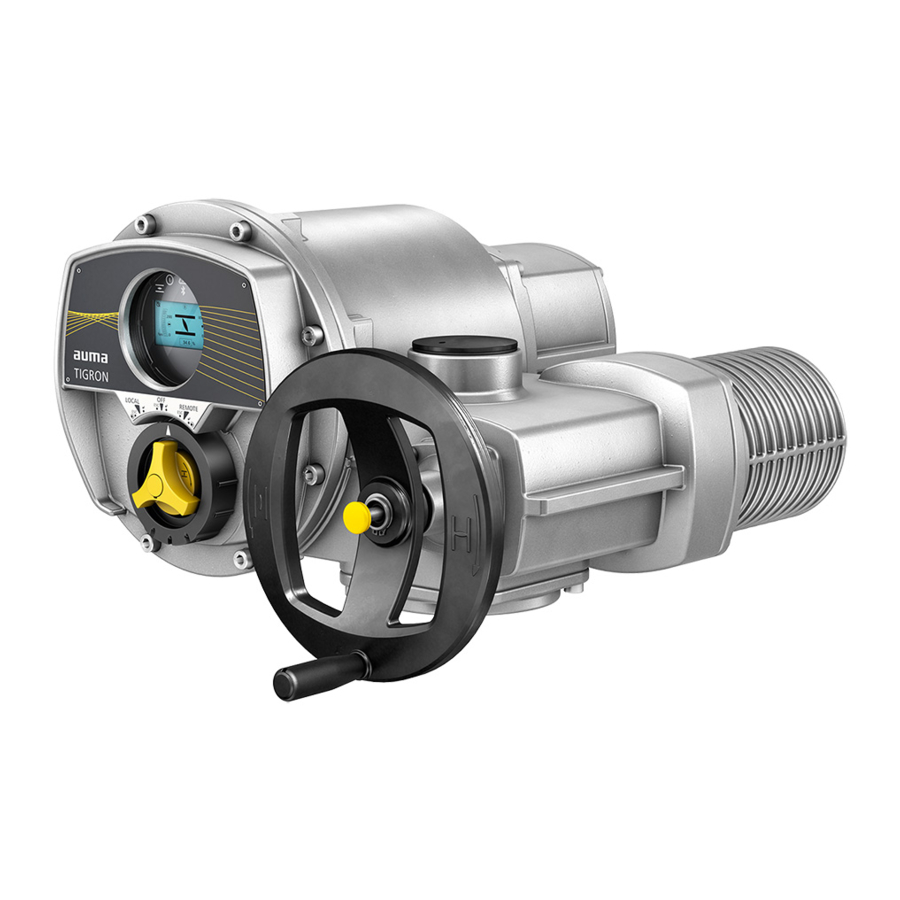
AUMA TIGRON TR-M30X Short Instructions
Multi-turn actuators modbus rtu
Hide thumbs
Also See for TIGRON TR-M30X:
- Manual (132 pages) ,
- Operation instructions manual (76 pages) ,
- Short instructions (8 pages)
Advertisement
Multi-turn actuators
TIGRON
TR-M30X
Modbus RTU
Use short instructions in combination with operation instructions only!
These short instructions are only complete with the respective operation instructions of the
actuator. Safety and warning instructions contained in the actuator operation instructions must
be heeded when performing work on the actuator!
Short instructions
TR-M1000X
Fieldbus connection
Advertisement
Table of Contents

Summary of Contents for AUMA TIGRON TR-M30X
- Page 1 Multi-turn actuators TIGRON TR-M30X TR-M1000X Modbus RTU Use short instructions in combination with operation instructions only! These short instructions are only complete with the respective operation instructions of the actuator. Safety and warning instructions contained in the actuator operation instructions must be heeded when performing work on the actuator! Short instructions Fieldbus connection...
-
Page 2: Table Of Contents
Table of contents Table of contents Page Basic information on fieldbus connection................Fieldbus connection for line topology................. Fieldbus connection for loop topology................Set fieldbus (slave address) via device menu..............Modbus parameter overview in device menu.............. -
Page 3: Basic Information On Fieldbus Connection
The electrical connection of the actuator must be opened to be able to connect the Electrical connection fieldbus cables. Refer to Operation instructions “Multi-turn actuators TIGRON TR-M30X TR-M1000X” (Y009.100), “Electrical connection” chapter. The Electrical connection” chapter of the operation instructions fully applies to the connection of the fieldbus cables. -
Page 4: Fieldbus Connection For Line Topology
Fieldbus connection for line topology Fieldbus connection for line topology Figure 1: Line topology □ Channel 1: Further fieldbus devices follow ▣ Channel 2 (redundancy only): further fieldbus devices follow Last fieldbus device ■ Fieldbus cable from previous device (input) Fieldbus cable to next device (output) Connection at terminal carrier For flexible cables, the fieldbus connection can be made via spring clamp terminals... - Page 5 Fieldbus connection for line topology Figure 4: Terminal assignment of support terminals: Channel 1 (1A/1B) [XK] Terminal assignment according to wiring diagram (customer connection): □ Terminals 31 and 32 if another fieldbus device follows Terminals 31 34 if the actuator is the last fieldbus device ■...
-
Page 6: Fieldbus Connection For Loop Topology
Fieldbus connection for loop topology Fieldbus connection for loop topology Figure 6: Loop topology □ Channel 1 ▣ Channel 2 ■ Last fieldbus device Fieldbus cable from previous device (input) Fieldbus cable to next device (output) For loop topology, automatic termination is performed once the actuator controls Information are connected to the power supply. - Page 7 Fieldbus connection for loop topology Figure 8: Terminal assignment of support terminals (2-channel) [XK] Terminal assignment according to wiring diagram (customer connection) □ Channel 1 ▣ Channel 2 Fieldbus cable from previous device (input via channel 1) Fieldbus cable to next device (output via channel 2)
-
Page 8: Set Fieldbus (Slave Address) Via Device Menu
MD2 slave address M0409 Information: MD2 slave address M0409 menu will only be available if parameter Redundancy M0800 has been set to value AUMA redundancy I. For settings AUMA redundancy II and Loop redundancy, the address of the second channel is automatically assigned: MD1 slave address = MD2 slave address The display shows parameter PRM3592 or PRM3593. -
Page 9: Modbus Parameter Overview In Device Menu
Modbus parameter overview in device menu Modbus parameter overview in device menu Device menu parameters can also be set via the AUMA CDT software. For information on AUMA CDT, refer to the operation instructions and our website at www.auma.com. For further information on these parameters and all other settings, refer to the Manual (Operation and setting). - Page 10 AUMA Riester GmbH & Co. KG P.O. Box 1362 DE 79373 Muellheim Tel +49 7631 809 - 0 Fax +49 7631 809 - 1250 info@auma.com www.auma.com Y009.410/003/en/1.21 For detailed information on AUMA products, refer to the Internet: www.auma.com...


Need help?
Do you have a question about the TIGRON TR-M30X and is the answer not in the manual?
Questions and answers