AUMA TIGRON TR-M30X Manual
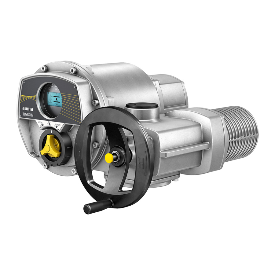
Multi-turn actuators
Hide thumbs
Also See for TIGRON TR-M30X:
- Manual (132 pages) ,
- Operation instructions manual (76 pages) ,
- Short instructions (10 pages)

Related Manuals for AUMA TIGRON TR-M30X


Summary of Contents for AUMA TIGRON TR-M30X
- Page 1 Multi-turn actuators TIGRON TR-M30X TR-M1000X Profibus DP Manual Device integration...
- Page 2 This document is intended to support the actuator integration into the DCS via fieldbus interface. Reference documents: Operation instructions (Assembly and commissioning) for the actuator Reference documents can be downloaded from the Internet (www.auma.com) or ordered directly from AUMA (refer to <Addresses>). Table of contents Page Safety instructions.........................
- Page 3 Multi-turn actuators Profibus DP Table of contents Technical data......................... 6.1. Profibus DP interface Index............................
-
Page 4: Safety Instructions
Multi-turn actuators Safety instructions Profibus DP Safety instructions 1.1. Prerequisites for the safe handling of the product The end user or the contractor must ensure that all legal requirements, directives, Standards/directives guidelines, national regulations and recommendations with respect to assembly, electrical connection, commissioning and operation are met at the place of installation. - Page 5 Any device modification requires prior written consent of the manufacturer. 1.2. Range of application AUMA multi-turn actuators are designed for the operation of industrial valves, e.g. globe valves, gate valves, butterfly valves, and ball valves. Other applications require explicit (written) confirmation by the manufacturer.
-
Page 6: General Information About Profibus Dp
Master devices without an external request. Within the Profibus protocol, masters are also called ‘active devices’. Slave devices such as AUMA Profibus DP actuators are peripheral devices. Typical Slave device slave devices are input/output devices, valves, actuators, and measuring transducers. - Page 7 Adjustable failure behaviour 2.7. Device types DP master class 2 (DPM2), e.g. programming/configuration tools DP master class 1 (DPM1), e.g. central controllers such as PLC, PC DP slave, e.g. AUMA Profibus DP devices. Devices with binary or analogue inputs/outputs, actuators, plug valves...
- Page 8 If a configuration with consistent data is selected, certain PLCs require special function blocks for the control of the Profibus DP slaves. AUMA actuators with Profibus DP are certified by the Profibus user organisation Certification (PNO).
- Page 9 Manual (Operation and Setting). Using AUMA CDT service software (via PC or laptop with Bluetooth). The latest version of AUMA CDT can be downloaded from our website: www.auma.com. Via fieldbus, please note that only one device with the address 126 (default value) is be connected to Profibus DP.
- Page 10 9 to 40.This way, the DP master saves memory space since only 8 input bytes are reserved for the actuator. Data issued by AUMA actuators shall be consistently processed by the DP master. This ensures that the value of a 2-byte variable (position transmitter, analogue customer input) does not change after reading out the first byte and, thus, does not distort the value.
- Page 11 Part of the device-specific I & M information is the unambiguous (asset) identification using a manufacturer ID (MANUFACTURER_ID, for AUMA actuators = 319), the order number (ORDER_ID) of the actuator as and well as the individual serial number (SERIAL_NUMBER).
- Page 12 Multi-turn actuators Description of the data interface Profibus DP Description of the data interface 4.1. Input data (process representation input) signals The process representation input allows the master (controls) to read the state of the slave (actuator). 4.1.1. Process representation input (default process representation) Grey bits are collective signals.
- Page 13 Multi-turn actuators Profibus DP Description of the data interface...
- Page 14 Multi-turn actuators Description of the data interface Profibus DP 4.1.2. Description of the bytes in the process representation input Byte 1: Logic signals Bits 3, 6, and 7 are collective signals. Bits 5 and 4 of the logical signals (byte1) indicate a logical operation of the actuator, i.e.
- Page 15 Multi-turn actuators Profibus DP Description of the data interface Byte 2: Actuator signals Table 2: Byte 2: Actuator signals Designation Prm-Text-Def GSD file Value Description (process representation) Thermal fault (56) = "Bit: Thermal fault" Motor protection tripped. No signal. Phase fault (57) = "Bit: Phase fault"...
- Page 16 (15) = "Bit: Device ok" Collective signal 05: The device is ready for remote control. No AUMA warnings, AUMA faults or signals according to NAMUR are present. Bit 7 is set if bits 0 to 6 are deleted. Contains the result of a disjunction (OR-operation) of bits 0 to 6 (device status).
- Page 17 Multi-turn actuators Profibus DP Description of the data interface Designation Prm-Text-Def GSD file Value Description (process representation) Handwheel oper. (28) = "Bit: Running via Output drive rotates without electric operation command. handw." No signal. Running REMOTE (27) = "Bit: Running RE- Output drive rotates due to operation command from MOTE"...
- Page 18 Multi-turn actuators Description of the data interface Profibus DP Bytes 9 and 10: Input AIN 1 Byte 9 = high byte, byte 10 = low byte. Bytes 9 and 10 transmit the value of the first additional free analogue current input of the Profibus DP interface.
- Page 19 Multi-turn actuators Profibus DP Description of the data interface Byte 14: Not ready REMOTE 2 Table 8: Byte 14: Not ready REMOTE 2 Designation Prm-Text-Def GSD file Value Description (process representation) — — No signal (reserved). — — No signal (reserved). SIL function active (207) = "SIL function act- Safety function of the SIL module is active.
- Page 20 Multi-turn actuators Description of the data interface Profibus DP Byte 16: Fault 2 The fault signals contain the causes why the actuator cannot be operated. Table 10: Byte 16: Fault 2 Designation Prm-Text-Def GSD file Value Description (process representation) — —...
- Page 21 Multi-turn actuators Profibus DP Description of the data interface Designation Prm-Text-Def GSD file Value Description (process representation) 24 V DC external (68) = "Bit: 24 V DC, extern- The external 24 V DC voltage supply of the controls has al" exceeded the power supply limits.
- Page 22 Designation Prm-Text-Def GSD file Value Description (process representation) Mainten. mechanics (209) = "Mechanic lifetime" Mechanic maintenance requirement (AUMA Service) No signal. Mainten. seals (210) = "Seal lifetime" Seal maintenance requirement (AUMA Service) No signal. Mainten. lubricant (211) = "Seal lifetime"...
- Page 23 Multi-turn actuators Profibus DP Description of the data interface Table 17: Byte 25: Out of specification 1 Designation Prm-Text-Def GSD file Value Description (process representation) — — No signal (reserved). — — No signal (reserved). — — No signal (reserved). —...
- Page 24 Multi-turn actuators Description of the data interface Profibus DP Designation Prm-Text-Def GSD file Value Description (process representation) Internal warning (70) = "Bit: Internal warn- Collective signal 15: Internal warning ing" No internal warning Wrn op.mode starts (85) = "Bit: WrnOnTiStarts" Warning: Max.
- Page 25 Multi-turn actuators Profibus DP Description of the data interface Designation Prm-Text-Def GSD file Value Description (process representation) PVST active (116) = "Bit: PVST active" Partial Valve Stroke Test function (PVST) is active. No signal. — — No signal (reserved). — —...
- Page 26 Multi-turn actuators Description of the data interface Profibus DP Designation Prm-Text-Def GSD file Value Description (process representation) — — No signal (reserved). — — No signal (reserved). — — No signal (reserved). The safety function indications via fieldbus are for information only and must not be used as part of a safety function. The I/O signals of the SIL module must be used for this purpose.
- Page 27 Multi-turn actuators Profibus DP Description of the data interface 4.2.2. Description of the output data Byte 1: Commands Table 24: Byte 1: Commands Designation Value Description (process representation) Fieldbus OPEN Operation command in direction OPEN. No command Fieldbus CLOSE Operation command in direction CLOSE. No command Fieldbus SETPOINT Run to setpoint.
- Page 28 Multi-turn actuators Description of the data interface Profibus DP To avoid placing too much strain on the actuator mechanics, reversion of direc- tion is delayed. The default setting in the factory for the reversing prevention time is 300 ms. Bits 4 through 7 are not used and must be set to 0. Bits 4, 5, 6, 7 Byte 2: Reserve The contents are reserved for future extensions.
- Page 29 Multi-turn actuators Profibus DP Description of the data interface Table 26: Byte 6: Operation commands for intermediate positions Value Behaviour 0x01 Position 1 is approached selecting the shortest travel. 0x02 Position 2 is approached selecting the shortest travel. 0x04 Position 3 is approached selecting the shortest travel. 0x08 Position 4 is approached selecting the shortest travel.
- Page 30 Multi-turn actuators Description of the data interface Profibus DP Value ≙ Operation direction/posi- Behaviour tion 0x99 CW Position 9 Position 9 is approached in clockwise direction (CW). 0x9A CW Position 10 Position 10 is approached in clockwise direction (CW). 0x9B CW Position 11 Position 11 is approached in clockwise direction (CW).
- Page 31 Multi-turn actuators Profibus DP Description of the data interface Byte 8: Digital outputs 2 Table 29: Byte 8: Digital outputs 2 Designation Value Description (process representation) Fieldbus DOUT 1 Digital output 1 is activated. Output is deactivated. Fieldbus DOUT 2 Digital output 2 is activated.
- Page 32 Multi-turn actuators Description of the data interface Profibus DP The actuator supports an acyclic DP-V1 connection with controls (DPM1 = master of class 1) and one acyclic DP-V1 connection with engineering stations (DPM2 = master of class 2). The following DP-V1 fault indications are supported: Fault indication Error Error...
-
Page 33: Corrective Action
Multi-turn actuators Profibus DP Corrective action Corrective action 5.1. Troubleshooting In case of problems with Profibus DP communication, the actuator provides important information on troubleshooting via the display (menu Diagnostics M0022). The indication and diagnostic LEDs on the Profibus DP board can also be used as support. - Page 34 Multi-turn actuators Corrective action Profibus DP Table 31: Information on Profibus DP 1 Indication on display Value and description DP1 slave address M0547 Bus address (slave address) DP1 baud rate M0099 Baud rate DP1 watchdog status M0411 Watchdog status Baud search The Profibus DP interface searches a baud rate.
- Page 35 Multi-turn actuators Profibus DP Corrective action Indication on display Value and description DP-V1 (SetPrm) DP-V1 function in parameter telegram (SetPrm) Deactivated DP-V1 services were deactivated using the parameters of the parameter telegram (SetPrm). Activated DP-V1 services were activated using the parameters of the parameter telegram (SetPrm).
-
Page 36: Technical Data
Information on the customer-specific version, refer to the order-related data sheet. The technical data sheet can be downloaded from the Internet in both German and English at ht- tp://www.auma.com (please state the order number). 6.1. Profibus DP interface Settings/programming the Profibus DP interface... - Page 37 Multi-turn actuators Profibus DP Technical data Commands and signals of the Profibus DP interface Process representation output OPEN, STOP, CLOSE, position setpoint, RESET, EMERGENCY operation command, enable local controls, Interlock OPEN/CLOSE (command signals) Process representation input End positions OPEN, CLOSED (feedback signals) Actual position value Actual torque value, requires MWG in actuator...
- Page 38 Multi-turn actuators Index Profibus DP Index Bus access Certification Commissioning 4, 8 Communication monitoring Connection monitoring Control clear telegram Corrective action Data interface description Device Master Data (GSD) Device types Diagnostics Directives Fail safe telegram Fieldbus address Functionality I & M functions ID number Input data Maintenance...
- Page 40 AUMA Riester GmbH & Co. KG P.O. Box 1362 DE 79373 Muellheim Tel +49 7631 809 - 0 Fax +49 7631 809 - 1250 info@auma.com www.auma.com Y009.411/003/en/1.21 For detailed information on AUMA products, refer to the Internet: www.auma.com...
Need help?
Do you have a question about the TIGRON TR-M30X and is the answer not in the manual?
Questions and answers