Sign In
Upload
Manuals
Brands
Allied Telesis Manuals
Switch
AT-GS948MPX
Allied Telesis AT-GS948MPX Manuals
Manuals and User Guides for Allied Telesis AT-GS948MPX. We have
2
Allied Telesis AT-GS948MPX manuals available for free PDF download: Installation Manual
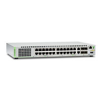
Allied Telesis AT-GS948MPX Installation Manual (120 pages)
AT-GS900MX Series GIGABIT ETHERNET SWITCHES
Brand:
Allied Telesis
| Category:
Switch
| Size: 7.27 MB
Table of Contents
Translated Safety Statements
5
Electrical Safety and Emissions Standards
3
Translated Safety Statements
4
Table of Contents
5
Table of Contents
11
Document Conventions
14
Contacting Allied Telesis
15
Chapter 1: Overview
17
Features
18
AT-GS900MX Models
18
10/100/1000 Mbps Twisted Pair Ports
18
Power over Ethernet
19
SFP Slots
19
S1 and S2 Stacking Slots
19
Leds
20
Installation Options
20
MAC Address Table
20
Management Software and Interfaces
20
Management Methods
20
Front and Back Panels
21
Figure 1: Front Panels of the AT-GS924MX and AT-GS924MPX Switches
21
Figure 2: Front Panels of the AT-GS948MX and AT-GS948MPX Switches
22
Figure 3: Back Panel of the AT-GS924MX Switch
23
Figure 4: Back Panel of the AT-GS924MPX and AT-GS948MPX Switches
23
Figure 5: Back Panel of the AT-GS948MX Switch
23
Management Panel
24
Figure 6: AT-GS900MX Series Management Panel
24
10/100/1000Base-T Twisted Pair Ports
25
Speed
25
Duplex Mode
25
Wiring Configuration
26
Maximum Distance
26
Power over Ethernet
26
Cable Requirements
26
Table 1: Twisted Pair Cable for the 10/100/1000Base-T Ports
26
Port Pinouts
27
Power over Ethernet
28
Poe Standards
28
Powered Device Classes
29
Cable Requirements
29
Table 2: IEEE Powered Device Classes
29
Table 3: Twisted Pair Cable Requirements for the 10/100Base-TX Ports at 10 or 100Mbps
29
Table 4: Twisted Pair Cable Requirements for the 10/100/1000Base-T Ports at 1000Mbps
30
Power Budget
31
Port Prioritization
31
Wiring Implementation
32
SFP Slots
33
Combo Twisted Pair Ports and SFP Slots
34
Table 5: Combo Port Pairs
34
Stacking Slots
35
Figure 7: Stacking Transceiver
35
Eco-Friendly Button
36
Leds
37
Leds for the Twisted Pair Ports
37
Figure 8: Leds for the Twisted Pair Ports on the AT-GS924MX and AT-GS948MX Switches
37
Leds for the Poe Twisted Pair Ports
38
Table 6: Leds on the Twisted Pair Ports on the AT-GS924MX and AT-GS948MX Switches
38
Figure 9: Leds for the Poe Twisted Pair Ports on the AT-GS924MPX and AT-GS948MPX Switches
39
Table 7: Leds for the Poe Twisted Pair Ports on the AT-GS924MPX and AT-GS948MPX Switches
39
Leds for the Combo Twisted Pair Ports
40
Figure 10: Leds for the Combo Twisted Pair Ports
41
Table 8: Leds on the Combo Twisted Pair Ports
41
Leds for the SFP Slots
42
Leds for the Stacking Slots
42
Figure 11: SFP Slot Leds
42
Table 9: SFP Slot Leds
42
Switch ID LED
43
Figure 12: Switch ID LED
43
Table 10: S1 and S2 Slot Leds
43
Figure 13: Switch ID LED Not in Low Power Mode
44
Figure 14: Switch ID Leds in Low Power Mode
44
USB Port
45
Console Port
46
Power Supply
47
Chapter 2: Beginning the Installation
49
Reviewing Safety Precautions
50
Choosing a Site for the Switch
54
Unpacking the Switch
55
Figure 15: Components of the Switches
55
Figure 16: Components of the AT-GS924MX Switch
56
Chapter 3: Installing the Switch on a Table or in an Equipment Rack
59
Selecting a Site for the Switch
60
Installing the Switch on a Table
61
Installing the Switch in an Equipment Rack
62
Figure 17: Turning the Switch Upside down
62
Figure 18: Removing the Rubber Feet
62
Figure 19: Installing Brackets on the AT-GS924MX Switch
63
Figure 20: Attaching Brackets to the AT-GS924MX, AT-GS948MX, and AT-GS948MPX Switches
64
Figure 21: Attaching Brackets to the AT-GS924MX, AT-GS948MX, and AT-GS948MPX Switches (Continued)
65
Figure 22: Mounting the Switch in an Equipment Rack
66
Chapter 4: Installing the Switch on a Wall
67
Installing the AT-GS924MX Switch on a Wall
68
Positions of the Switch on a Wall
68
Figure 23: Positions of the AT-GS924MX Switch on a Wall
68
Recommended Minimum Wall Area Dimensions
69
Figure 24: Minimum Wall Area Dimensions for the AT-GS924MX Switch with the Front Panel on the Left
69
Wall Guidelines
70
Figure 25: Minimum Wall Area Dimensions for the AT-GS924MX Switch with the Front Panel on the Right
70
Tools and Material
71
Installing the AT-GS924MX Switch
71
Figure 26: Attaching the Brackets to the AT-GS924MX Switch for Wall Installation
72
Figure 27: Marking the Locations of the Bracket Holes on a Concrete Wall
73
Figure 28: Installing the AT-GS924MX Switch on a Wall
75
Installing the AT-GS924MPX, AT-GS948MX, and AT-GS948MPX Switches on a Wall
76
Position of the Switch on the Wall
76
Recommended Minimum Wall Area Dimensions
76
Figure 29: Positions of the AT-GS924MPX, AT-GS948MX, and AT-GS948MPX Switches on a Wall
76
Figure 30: Minimum Wall Area Dimensions for the Switch When the Front Panel Is on the Left
77
Figure 31: Minimum Wall Area Dimensions for the Switch When the Front Panel Is on the Right
77
Positions of the Brackets
78
Plywood Base for a Wall with Wooden Studs
78
Figure 32: Bracket Positions on the Switch
78
Figure 33: Switch on a Plywood Base
79
Figure 34: Distances between the Brackets on the AT-GS924MPX, AT-GS948MX, and AT-GS948MPX Switches
80
Wall Guidelines
81
Figure 35: Steps to Installing the Switch with a Plywood Base
81
Tools and Material
82
Installing the Plywood Base
82
Installing the Switch on the Plywood Base
82
Figure 36: Attaching the Brackets for Wall Installation for All Switches Except the AT-GS924MX Switch
83
Figure 37: Securing the Switch to the Plywood Base
84
Installing the Switch on a Concrete Wall
85
Figure 38: Marking the Locations of the Bracket Holes on a Concrete Wall
85
Figure 39: Installing the AT-GS924MPX, AT-GS948MX, or AT-GS948MPX Switch on a Wall
86
Chapter 5: Cabling the Networking Ports
89
Cabling the Twisted Pair Ports
90
Installing SFP Transceivers
92
Installing SFP Modules
93
Figure 40: Removing the Dust Plug from an SFP Slot
93
Figure 41: Installing an SFP Transceiver
93
Figure 42: Removing the Dust Cover from an SFP Transceiver
94
Figure 43: Positioning the SFP Handle in the Upright Position
94
Figure 44: Connecting a Fiber Optic Cable to an SFP Transceiver
95
Chapter 6: Powering on the Switch
97
Powering on the Switch
98
Figure 45: Installing the Retaining Clip
98
Figure 46: Raising the Retaining Clip
99
Figure 47: Plugging in the AC Power Cord
99
Figure 48: Lowering the Retaining Clip
99
Monitoring the Initialization Processes
101
Figure 49: Switch Initialization Messages
101
Figure 50: Switch Initialization Messages (Continued)
102
Figure 51: Switch Initialization Messages (Continued)
103
Configuring the Switch for Stand-Alone Operations
104
Starting a Local Management Session
104
Figure 52: Connecting the Management Cable to the Console Port
105
Disabling Vcstack
106
Figure 53: User Exec Mode Prompt
106
Figure 54: SHOW STACK Command
106
Figure 55: Moving to the Global Configuration Mode
107
Figure 56: Confirmation Prompt for the no STACK ENABLE Command
107
Figure 57: Returning to the Privileged Exec Mode
108
Figure 58: Saving the Changes with the WRITE Command
108
Specifying Ports in the Command Line Interface for Stand-Alone Switches
109
Figure 59: PORT Parameter in the Command Line Interface
109
Chapter 7: Troubleshooting
111
Appendix A: Technical Specifications
115
Physical Specifications
115
Table 11: Product Dimensions
115
Table 12: Product Weights
115
Environmental Specifications
116
Power Specifications
116
Table 13: Ventilation Requirements
116
Table 14: Environmental Specifications
116
Table 15: Input Voltages
116
Certifications
117
Table 16: Maximum Power Consumption
117
Table 17: Heat Dissipation
117
Table 18: Product Certifications
117
RJ-45 Twisted Pair Port Pinouts
118
Figure 60: RJ-45 Socket Pin Layout (Front View)
118
Table 19: Pin Signals for 10 and 100 Mbps
118
Table 20: Pin Signals for 1000 Mbps
118
RJ-45 Style Serial Console Port Pinouts
119
Table 21: RJ-45 Style Serial Console Port Pin Signals
119
Advertisement
Allied Telesis AT-GS948MPX Installation Manual (118 pages)
Brand:
Allied Telesis
| Category:
Switch
| Size: 7.41 MB
Table of Contents
Electrical Safety and Emissions Standards
3
Translated Safety Statements
4
Table of Contents
5
Document Conventions
12
Contacting Allied Telesis
13
Chapter 1: Overview
15
Features
16
AT-GS900MX Models
16
10/100/1000 Mbps Twisted Pair Ports
16
Power over Ethernet
17
SFP Slots
17
S1 and S2 Stacking Slots
17
Leds
18
Installation Options
18
MAC Address Table
18
Management Software and Interfaces
18
Management Methods
18
Front and Back Panels
19
Figure 1: Front Panels of the AT-GS924MX and AT-GS924MPX Switches
19
Figure 2: Front Panels of the AT-GS948MX and AT-GS948MPX Switches
20
Figure 3: Back Panel of the AT-GS924MX Switch
21
Figure 4: Back Panel of the AT-GS924MPX and AT-GS948MPX Switches
21
Figure 5: Back Panel of the AT-GS948MX Switch
21
Management Panel
22
Figure 6: AT-GS900MX Series Management Panel
22
10/100/1000Base-T Twisted Pair Ports
23
Speed
23
Duplex Mode
23
Wiring Configuration
24
Maximum Distance
24
Power over Ethernet
24
Cable Requirements
24
Table 1: Twisted Pair Cable for the 10/100/1000Base-T Ports
24
Port Pinouts
25
Power over Ethernet
26
Poe Standards
26
Powered Device Classes
27
Cable Requirements
27
Table 2: IEEE Powered Device Classes
27
Table 3: Twisted Pair Cable Requirements for the 10/100Base-TX Ports at 10 or 100Mbps
27
Table 4: Twisted Pair Cable Requirements for the 10/100/1000Base-T Ports at 1000Mbps
28
Power Budget
29
Port Prioritization
29
Wiring Implementation
30
SFP Slots
31
Combo Twisted Pair Ports and SFP Slots
32
Table 5: Combo Port Pairs
32
Stacking Slots
33
Figure 7: Stacking Transceiver
33
Eco-Friendly Button
34
Leds
35
Leds for the Twisted Pair Ports
35
Figure 8: Leds for the Twisted Pair Ports on the AT-GS924MX and AT-GS948MX Switches
35
Leds for the Poe Twisted Pair Ports
36
Table 6: Leds on the Twisted Pair Ports on the AT-GS924MX and AT-GS948MX Switches
36
Figure 9: Leds for the Poe Twisted Pair Ports on the AT-GS924MPX and AT-GS948MPX Switches
37
Table 7: Leds for the Poe Twisted Pair Ports on the AT-GS924MPX and AT-GS948MPX Switches
37
Leds for the Combo Twisted Pair Ports
38
Figure 10: Leds for the Combo Twisted Pair Ports
39
Table 8: Leds on the Combo Twisted Pair Ports
39
Leds for the SFP Slots
40
Leds for the Stacking Slots
40
Figure 11: SFP Slot Leds
40
Table 9: SFP Slot Leds
40
Switch ID LED
41
Figure 12: Switch ID LED
41
Table 10: S1 and S2 Slot Leds
41
Figure 13: Switch ID LED Not in Low Power Mode
42
Figure 14: Switch ID Leds in Low Power Mode
42
USB Port
43
Console Port
44
Power Supply
45
Chapter 2: Virtual Chassis Stacking
47
Overview
48
Stacking Slots and Transceivers
49
Figure 15: Stacking Transceiver
49
Stacking Port Topologies
50
Figure 16: Stack of Two Switches in the Linear Topology
50
Figure 17: Stack of Four Switches in the Linear Topology
51
Figure 18: Stack of Two Switches in the Ring Topology
52
Figure 19: Stack of Four Switches in the Ring Topology
53
Master and Member Switches
54
Selection of the Master Switch
54
ID Numbers
55
Specifying Ports in the Command Line Interface
56
Figure 20: PORT Parameter in the Command Line Interface
56
Chapter 3: Beginning the Installation
57
Reviewing Safety Precautions
58
Selecting a Site for the Stack
62
Planning a Stack
64
Unpacking the Switch
65
Figure 21: Components of the Switches
65
Figure 22: Components of the AT-GS924MX Switch
66
Chapter 4: Installing the Switch on a Table or in an Equipment Rack
69
Installing the Switch on a Table
70
Installing the Switch in an Equipment Rack
71
Figure 23: Turning the Switch Upside down
71
Figure 24: Removing the Rubber Feet
71
Figure 25: Installing Brackets on the AT-GS924MX Switch
72
Figure 26: Attaching Brackets to the AT-GS924MPX, AT-GS948MX, or AT-GS948MPX Switch
73
Figure 27: Attaching Brackets to the AT-GS924MPX, AT-GS948MX, or AT-GS948MPX Switch (Continued)
74
Figure 28: Mounting the Switch in an Equipment Rack
75
Chapter 5: Verifying the Status of Vcstack
77
Verifying the Status of Vcstack
78
Activating the Vcstack Feature
79
Starting a Local Management Session
79
Figure 29: Connecting the Management Cable to the Console Port
79
Activating Vcstack
80
Figure 30: User Exec Mode Prompt
80
Figure 31: Moving to the Privileged Exec Mode with the ENABLE Command
80
Figure 32: Moving to the Global Configuration Mode with the CONFIGURE TERMINAL Command
80
Figure 33: Activating Vcstack with the STACK ENABLE Command
81
Figure 34: Returning to the Privileged Exec Mode with the EXIT Command
81
Figure 35: Saving the Change with the WRITE Command
81
Figure 36: Rebooting the Switch with the REBOOT Command
81
Chapter 6: Cabling the Stacking Ports
83
Figure 37: Removing the Dust Plug from the S1 Slot
83
Figure 38: Removing the Dust Cover from the Transceiver
84
Figure 39: Installing the Transceiver in Slot S1
84
Figure 40: Removing the Dust Plug from the S2 Slot
85
Figure 41: Installing the Transceiver in Slot S2
86
Chapter 7: Powering on the Stack
87
Installing the Power Cord Retaining Clip
88
Figure 42: Installing the Retaining Clip
88
Powering on the Switches Individually
89
Figure 43: Plugging in the AC Power Cord
90
Figure 44: Lowering the Retaining Clip
91
Powering on the Switches Simultaneously
92
Verifying the Stack
94
Figure 45: SHOW STACK Command
94
Figure 46: Moving to the Global Configuration Mode with the CONFIGURE TERMINAL Command
95
Setting the Priority Numbers
95
Figure 47: Returning to the Privileged Exec Mode
96
Figure 48: Saving the Priority Values with the WRITE Command
96
Monitoring the Initialization Processes
97
Figure 49: Switch Initialization Messages
97
Figure 50: Switch Initialization Messages (Continued)
98
Figure 51: Switch Initialization Messages (Continued)
99
Chapter 8: Cabling the Networking Ports
101
Cabling the Twisted Pair Ports
102
Installing SFP Transceivers
104
Figure 52: Removing the Dust Plug from an SFP Slot
105
Figure 53: Installing an SFP Transceiver
105
Figure 54: Removing the Dust Cover from an SFP Transceiver
106
Figure 55: Positioning the SFP Handle in the Upright Position
106
Figure 56: Connecting a Fiber Optic Cable to an SFP Transceiver
107
Chapter 9: Troubleshooting
109
Appendix A: Technical Specifications
113
Physical Specifications
113
Table 11: Product Dimensions
113
Table 12: Product Weights
113
Environmental Specifications
114
Power Specifications
114
Table 13: Ventilation Requirements
114
Table 14: Environmental Specifications
114
Table 15: Input Voltages
114
Certifications
115
Table 16: Maximum Power Consumption
115
Table 17: Heat Dissipation
115
Table 18: Product Certifications
115
RJ-45 Twisted Pair Port Pinouts
116
Figure 57: RJ-45 Socket Pin Layout (Front View)
116
Table 19: Pin Signals for 10 and 100 Mbps
116
RJ-45 Style Serial Console Port Pinouts
117
Table 20: Pin Signals for 1000 Mbps
117
Table 21: RJ-45 Style Serial Console Port Pin Signals
117
Advertisement
Related Products
Allied Telesis AT-GS948
Allied Telesis AT-GS948MX
Allied Telesis AT AT-GS900/24
Allied Telesis AT-GS950/48
Allied Telesis AT-GS924
Allied Telesis AT-GS950/48PS
Allied Telesis AT-GS924MX
Allied Telesis AT-GS910/5
Allied Telesis AT-GS910/16
Allied Telesis AT-GS920/8
Allied Telesis Categories
Switch
Network Router
Media Converter
Network Hardware
Wireless Access Point
More Allied Telesis Manuals
Login
Sign In
OR
Sign in with Facebook
Sign in with Google
Upload manual
Upload from disk
Upload from URL