
Related Manuals for Allied Telesis AT-GS924MX


Summary of Contents for Allied Telesis AT-GS924MX
- Page 1 AT-GS900MX Series GIGABIT ETHERNET SWITCHES AT-GS924MX AT-GS924MPX AT-GS948MX AT-GS948MPX Installation Guide for VCStack ™ 613-002085 Rev. A...
- Page 2 Allied Telesis, Inc. has been advised of, known, or should have known, the...
-
Page 3: Electrical Safety And Emissions Standards
Electrical Safety and Emissions Standards This product meets the following standards. U.S. Federal Communications Commission Radiated Energy Note: This equipment has been tested and found to comply with the limits for a Class A digital device pursuant to Part 15 of FCC Rules. -
Page 4: Translated Safety Statements
Translated Safety Statements Important: Safety statements that have the symbol are translated into multiple languages in the Translated Safety Statements document at www.alliedtelesis.com/support. -
Page 5: Table Of Contents
Contents Document Conventions ...............................12 Contacting Allied Telesis ..............................13 Chapter 1: Overview ................................ 15 Features ....................................16 AT-GS900MX Models ..............................16 10/100/1000 Mbps Twisted Pair Ports .........................16 Power over Ethernet..............................17 SFP Slots ..................................17 S1 and S2 Stacking Slots .............................17 LEDs.....................................18 Installation Options ...............................18 MAC Address Table ..............................18... - Page 6 Contents Stacking Port Topologies ..............................50 Master and Member Switches ............................54 Selection of the Master Switch ............................ 54 ID Numbers ................................. 55 Specifying Ports in the Command Line Interface........................ 56 Chapter 3: Beginning the Installation ..........................57 Reviewing Safety Precautions ............................58 Selecting a Site for the Stack..............................
- Page 7 Figure 6: AT-GS900MX Series Management Panel......................22 Figure 7: Stacking Transceiver .............................33 Figure 8: LEDs for the Twisted Pair Ports on the AT-GS924MX and AT-GS948MX Switches ..........35 Figure 9: LEDs for the PoE Twisted Pair Ports on the AT-GS924MPX and AT-GS948MPX Switches........37 Figure 10: LEDs for the Combo Twisted Pair Ports......................39...
- Page 8 Figures Figure 50: Switch Initialization Messages (Continued) ......................98 Figure 51: Switch Initialization Messages (Continued) ......................99 Figure 52: Removing the Dust Plug from an SFP Slot......................105 Figure 53: Installing an SFP Transceiver..........................105 Figure 54: Removing the Dust Cover from an SFP Transceiver..................106 Figure 55: Positioning the SFP Handle in the Upright Position...................106 Figure 56: Connecting a Fiber Optic Cable to an SFP Transceiver..................107 Figure 57: RJ-45 Socket Pin Layout (Front View).......................116...
- Page 9 Table 4: Twisted Pair Cable Requirements for the 10/100/1000Base-T Ports at 1000Mbps ..........28 Table 5: Combo Port Pairs ..............................32 Table 6: LEDs on the Twisted Pair Ports on the AT-GS924MX and AT-GS948MX Switches ..........36 Table 7: LEDs for the PoE Twisted Pair Ports on the AT-GS924MPX and AT-GS948MPX Switches ........37 Table 8: LEDs on the Combo Twisted Pair Ports ........................39...
- Page 10 Tables...
- Page 11 Series of Layer 2+ Gigabit Ethernet switches. This preface contains the following sections: “Document Conventions” on page 12 “Contacting Allied Telesis” on page 13 Note This guide explains how to install the switches in a stack with the ™...
-
Page 12: Document Conventions
Preface Document Conventions This document uses the following conventions: Note Notes provide additional information. Caution Cautions inform you that performing or omitting a specific action may result in equipment damage or loss of data. Warning Warnings inform you that performing or omitting a specific action may result in bodily injury. -
Page 13: Contacting Allied Telesis
AT-GS900MX Series Installation Guide for VCStack Contacting Allied Telesis If you need assistance with this product, you may contact Allied Telesis technical support by going to the Support & Services section of the Allied Telesis web site at www.alliedtelesis.com/support. You can find links for the following services on this page: 24/7 Online Support —... - Page 14 Preface...
-
Page 15: Chapter 1: Overview
Chapter 1 Overview This chapter contains the following sections: “Features” on page 16 “Front and Back Panels” on page 19 “Management Panel” on page 22 “10/100/1000Base-T Twisted Pair Ports” on page 23 “Power over Ethernet” on page 26 ... -
Page 16: Features
Chapter 1: Overview Features The AT-GS900MX Series Switches and their features are listed in this section: AT-GS900MX Here are model names of the AT-GS900MX Series switches: Models AT-GS924MX AT-GS924MPX AT-GS948MX AT-GS948MPX 10/100/1000 Here are the basic features of the 10/100/1000 Mbps twisted pair ports:... -
Page 17: Power Over Ethernet
Supports 1000Base-ZX SFP transceivers Note SFP transceivers must be purchased separately. For a list of supported transceivers, contact your Allied Telesis distributor or reseller. Note The SFP slots are paired with two twisted pair 10/100/1000Base-T ports to form combo port pairs. For information, refer to “Combo Twisted Pair Ports and SFP Slots”... -
Page 18: Leds
Desk or tabletop Note The switches come with wall anchors and screws. Allied Telesis does not recommend installing the switches of a stack on a wall. Instead, they should be installed in an equipment rack or on a table. -
Page 19: Front And Back Panels
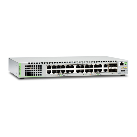
Figure 1 here and Figure 2 on page 20. AT-GS924MX 10/100/1000Base-T Ports SFP Slots Stacking Slots Management Panel AT-GS924MPX 10/100/1000Base-T Ports with PoE 10/100/1000Base-T Ports SFP Slots Stacking Slots Management Panel Figure 1. Front Panels of the AT-GS924MX and AT-GS924MPX Switches... -
Page 20: Figure 2: Front Panels Of The At-Gs948Mx And At-Gs948Mpx Switches
Chapter 1: Overview AT-GS948MX 10/100/1000Base-T Ports SFP Slots Stacking Slots Management Panel AT-GS948MPX 10/100/1000Base-T Ports with PoE 10/100/1000Base-T Ports SFP Slots Stacking Slots Management Panel Figure 2. Front Panels of the AT-GS948MX and AT-GS948MPX Switches... -
Page 21: Figure 3: Back Panel Of The At-Gs924Mx Switch
AT-GS900MX Series Installation Guide for VCStack The back panel of the AT-GS924MX Switch is shown in Figure 3. AC Power Connector Figure 3. Back Panel of the AT-GS924MX Switch The back panel of the AT-GS924MPX and AT-GS948MPX Switches is shown in Figure 4. -
Page 22: Management Panel
Chapter 1: Overview Management Panel Figure 6 identifies the components in the management panels on the AT-GS900MX Series switches. Console Management Port eco-friendly button Switch ID LED USB Port Figure 6. AT-GS900MX Series Management Panel... -
Page 23: 10/100/1000Base-T Twisted Pair Ports
AT-GS900MX Series Installation Guide for VCStack 10/100/1000Base-T Twisted Pair Ports The AT-GS900MX Series switches have 24 or 48 10/100/1000Base-T ports, depending on the model. Note Two twisted pair ports are paired with the SFP slots to form combo ports. For information, refer to “Combo Twisted Pair Ports and SFP Slots”... -
Page 24: Wiring Configuration
Chapter 1: Overview Wiring The wiring configuration of a port operating at 10 or 100 Mbps can be MDI or MDI-X. The wiring configurations of a switch port and a network device Configuration connected with straight-through twisted pair cabling have to be opposite, such that one device is using MDI and the other MDI-X. -
Page 25: Port Pinouts
AT-GS900MX Series Installation Guide for VCStack Port Pinouts Refer to Table 19 on page 116 and Table 20 on page 117 for the port pinouts of the 10/100/1000Base-T twisted pair ports. -
Page 26: Power Over Ethernet
Chapter 1: Overview Power over Ethernet The AT-GS924MPX and AT-GS948MPX Switches feature Power over Ethernet (PoE) on the 10/100/1000Base-T ports. PoE is used to supply power to network devices over the same twisted pair cables that carry the network traffic. The main advantage of PoE is that it can make it easier to install a network. -
Page 27: Powered Device Classes
AT-GS900MX Series Installation Guide for VCStack Powered Device Powered devices are grouped into the five classes listed in Table 2. The classes are based on the amount of power the devices require. The Classes switches support all five classes. Table 2. IEEE Powered Device Classes Maximum Power Class Output from a Switch... -
Page 28: Table 4: Twisted Pair Cable Requirements For The 10/100/1000Base-T Ports At 1000Mbps
Chapter 1: Overview Table 3. Twisted Pair Cable Requirements for the 10/100Base-TX Ports at 10 or 100Mbps 10Mbps 100Mbps Cable Type Non- Non- PoE+ PoE+ Standard TIA/EIA 568-B- compliant Category 6 or 6a shielded cabling. The cable requirements for ports operating at 1000Mbps are given in Table 4. -
Page 29: Power Budget
AT-GS900MX Series Installation Guide for VCStack Power Budget The AT-GS924MPX and AT-GS948MPX Switches have a power budget of 370 watts. This is the maximum amount of power the switches can provide at one time to the powered devices. The power requirements of the PoE devices determine the maximum number of devices the switch can support at one time. -
Page 30: Wiring Implementation
Chapter 1: Overview High priority level, power is provided to the ports based on port number, in ascending order. The lowest priority level is Low. This is the default setting. Ports set to this level only receive power if all of the ports assigned to the other two levels are already receiving power. -
Page 31: Sfp Slots
The switches support a variety of short and long distance SFP modules. For a list of supported SFP modules, contact your Allied Telesis representative or visit our web site. Note The SFP slots and two twisted pair ports are paired together to form combo port pairs. -
Page 32: Combo Twisted Pair Ports And Sfp Slots
For example, if you decide to use twisted pair port 25R on the AT-GS924MX or AT-GS924MPX Switch, then you cannot use SFP slot 25. Or, if you choose to use SFP slot 49 on the AT-GS948MX or AT-GS948MPX Switch, then you cannot use the twisted pair port 49R. -
Page 33: Stacking Slots
AT-GS900MX Series Installation Guide for VCStack Stacking Slots The S1 and S2 slots on the front panel of the switch are used with the VCStack feature and the stacking transceiver to create a stack of up to four switches. The switches of a stack act as a single virtual unit. They synchronize their actions so that switching operations, like spanning tree protocols, virtual LANs, and static port trunks, span across all the units and ports. -
Page 34: Eco-Friendly Button
Chapter 1: Overview eco-friendly Button The eco-friendly button on the front panel of the switch is used to toggle the port LEDs on or off. You might turn off the LEDs to conserve electricity when you are not monitoring the device. You can also toggle the LEDs with the ECOFRIENDLY LED and NO ECOFRIENDLY LED commands in the Global Configuration mode of the command line interface. -
Page 35: Leds
LEDs are shown in Figure 8. Ports Duplex Mode Link/Activity LED Duplex Mode LED Link/Activity LED Figure 8. LEDs for the Twisted Pair Ports on the AT-GS924MX and AT-GS948MX Switches The LEDs are described in Table 6 on page 36. -
Page 36: Leds For The Poe Twisted Pair Ports
Chapter 1: Overview Table 6. LEDs on the Twisted Pair Ports on the AT-GS924MX and AT-GS948MX Switches State Description Solid Green A port has established a 1000 Mbps link to a network device. Flashing A port is transmitting or receiving data at Green 1000 Mbps. -
Page 37: Figure 9: Leds For The Poe Twisted Pair Ports On The At-Gs924Mpx And At-Gs948Mpx Switches
AT-GS900MX Series Installation Guide for VCStack Link/Activity LED PoE LED PoE LED Link/Activity LED Figure 9. LEDs for the PoE Twisted Pair Ports on the AT-GS924MPX and AT-GS948MPX Switches The LEDs are described in Table 7. Table 7. LEDs for the PoE Twisted Pair Ports on the AT-GS924MPX and AT-GS948MPX Switches State Description... -
Page 38: Leds For The Combo Twisted Pair Ports
To turn on the LEDs, use the eco-friendly button. LEDs for the Ports 25R and 26R on the AT-GS924MX and AT-GS924MPX Switches and ports 49R and 50R on the AT-GS948MX and AT-GS948MPX Combo Twisted Switches have two LEDs that display link, activity and duplex mode Pair Ports information. -
Page 39: Figure 10: Leds For The Combo Twisted Pair Ports
AT-GS900MX Series Installation Guide for VCStack Link/Activity LED Duplex Mode LED Link/Activity LED Duplex Mode LED Figure 10. LEDs for the Combo Twisted Pair Ports The LEDs are described in Table 8. Table 8. LEDs on the Combo Twisted Pair Ports State Description Solid Green... -
Page 40: Leds For The Sfp Slots
Chapter 1: Overview LEDs for the SFP The LEDs for the SFP slots are located between the slots, as shown in Figure 11. Each SFP slot has one LED. The left-hand LED is for the top Slots slot and the right-hand LED is for the bottom slot. SFP Slot LEDs Figure 11. -
Page 41: Switch Id Led
AT-GS900MX Series Installation Guide for VCStack Table 10. S1 and S2 Slot LEDs State Description Link/Activity The slot is empty, the stacking transceiver has not established a link to a network device, or the LEDs are turned off. To turn on the LEDs, use the eco-friendly button. -
Page 42: Figure 13: Switch Id Led Not In Low Power Mode
Chapter 1: Overview The switch is booting up. The switch has encountered a fault condition. The switch is operating as a stand-alone unit, with the ID number 0. The switch has an ID number of 1 to 4 as part of a VCStack. The dot in the lower right corner flashes when the switch accesses USB memory. -
Page 43: Usb Port
AT-GS900MX Series Installation Guide for VCStack USB Port The management panel has a USB port. You may use the port to store configuration files on flash drives and to restore configuration files to switches whose settings have been lost or corrupted, or to quickly configure replacement units. -
Page 44: Console Port
Chapter 1: Overview Console Port The Console port is used to conduct management sessions with the switch to configure its features and parameter settings. This type of management uses serial RS-232 and is commonly referred to as local or out-of-band management because it is not conducted over your network. To perform local management, you must be at the location of the switch and must use the management cable included with the switch. -
Page 45: Power Supply
AT-GS900MX Series Installation Guide for VCStack Power Supply The AT-GS900MX Series switches come with one AC power supply. The back panels have one AC connector. The power supply is not field- replaceable, refer to “Technical Specifications” on page 113 for the input voltage range. - Page 46 Chapter 1: Overview...
-
Page 47: Chapter 2: Virtual Chassis Stacking
Chapter 2 Virtual Chassis Stacking The sections in this chapter are: “Overview” on page 48 “Stacking Slots and Transceivers” on page 49 “Stacking Port Topologies” on page 50 “Master and Member Switches” on page 54 “Specifying Ports in the Command Line Interface” on page 56 ... -
Page 48: Overview
Chapter 2: Virtual Chassis Stacking Overview The Virtual Chassis Stack (VCStack) feature allows you to connect up to four AT-GS900MX Series switches to form a virtual switch so that the devices function as a single networking unit. The benefits of the VCStack feature are: Simplifies management - You can manage the devices of the stack ... -
Page 49: Stacking Slots And Transceivers
AT-GS900MX Series Installation Guide for VCStack Stacking Slots and Transceivers The AT-GS900MX Series Switches come with two stacking slots. The slots are labeled “S1” and “S2”. For stacking, the slots may only be used with the VCStack feature and with the AT-SP10TW transceiver. The stacking transceiver is shown in Figure 15. -
Page 50: Stacking Port Topologies
Chapter 2: Virtual Chassis Stacking Stacking Port Topologies The switches of a stack are connected with the S1 and S2 ports and AT- SP10TW transceiver, shown in Figure 15 on page 49. There are two wiring configurations. The first topology is called the linear topology. -
Page 51: Figure 17: Stack Of Four Switches In The Linear Topology
AT-GS900MX Series Installation Guide for VCStack Figure 17. Stack of Four Switches in the Linear Topology The second topology is called the ring topology. It is similar to the linear topology, except that the unused stacking slots on the end switches of the stack are connected to form a physical loop. -
Page 52: Figure 18: Stack Of Two Switches In The Ring Topology
Chapter 2: Virtual Chassis Stacking Figure 18. Stack of Two Switches in the Ring Topology Figure 19 on page 53 is an example of a stack of four switches in the ring topology. -
Page 53: Figure 19: Stack Of Four Switches In The Ring Topology
AT-GS900MX Series Installation Guide for VCStack Figure 19. Stack of Four Switches in the Ring Topology The topologies are the same in terms of network speed and performance. However, the ring topology is the recommended wiring configuration because of the secondary path through the stacking ports. The two pathways protect the switches of the stack against the loss of communications due to a failure of a stacking port, cable, or switch. -
Page 54: Master And Member Switches
Chapter 2: Virtual Chassis Stacking Master and Member Switches The stack has one master switch. The functions of the master switch include: Coordinating and monitoring stack operations. Verifying that the switches are using the same version of management software. It automatically downloads its management software over the stacking cables to switches with different software versions. -
Page 55: Id Numbers
AT-GS900MX Series Installation Guide for VCStack ID Numbers Each switch must be assigned an ID number. The range is 1 to 4, and the default is 1. The ID numbers are displayed on the ID LEDs on the front panels of the units. You may assign the numbers yourself or you can let the master switch assign the numbers automatically, as explained in Chapter 7, “Powering On the Stack”... -
Page 56: Specifying Ports In The Command Line Interface
Chapter 2: Virtual Chassis Stacking Specifying Ports in the Command Line Interface The command line interface in the management software on the switch has a parameter that you use to specify the individual ports. The parameter is the PORT parameter, and Figure 20 shows its format. port1 Stack ID Module ID... -
Page 57: Chapter 3: Beginning The Installation
Chapter 3 Beginning the Installation The chapter contains the following sections: “Reviewing Safety Precautions” on page 58 “Selecting a Site for the Stack” on page 62 “Planning a Stack” on page 64 “Unpacking the Switch” on page 65 ... -
Page 58: Reviewing Safety Precautions
Chapter 3: Beginning the Installation Reviewing Safety Precautions Please review the following safety precautions before beginning the installation procedure. Note Safety statements that have the symbol are translated into multiple languages in the Translated Safety Statements document at www.alliedtelesis.com/support. Warning Class 1 Laser product. - Page 59 AT-GS900MX Series Installation Guide for VCStack Warning Power cord is used as a disconnection device. To de-energize equipment, disconnect the power cord. Warning Class I Equipment. This equipment must be earthed. The power plug must be connected to a properly wired earth ground socket outlet.
- Page 60 Chapter 3: Beginning the Installation Caution Circuit Overloading: Consideration should be given to the connection of the equipment to the supply circuit and the effect that overloading of circuits might have on overcurrent protection and supply wiring. Appropriate consideration of equipment nameplate ratings should be used when addressing this concern.
- Page 61 AT-GS900MX Series Installation Guide for VCStack Note If installed in a closed or multi-unit rack assembly, the operating ambient temperature of the rack environment may be greater than the room ambient temperature. Therefore, consideration should be given to installing the equipment in an environment compatible with the manufacturer’s maximum rated ambient temperature (Tmra).
-
Page 62: Selecting A Site For The Stack
Chapter 3: Beginning the Installation Selecting a Site for the Stack Here are the site guidelines for the stack: Note The switches of the stack should be installed on a table or in an equipment rack. They should not be installed on a wall. The power outlets should be located near the switches and be ... - Page 63 AT-GS900MX Series Installation Guide for VCStack Warning Switches should not be stacked on top of one another on a table or desktop because that could present a personal safety hazard if you need to move or replace switches. ...
-
Page 64: Planning A Stack
Chapter 3: Beginning the Installation Planning a Stack Here are the guidelines to planning a stack: A stack can have up to four AT-GS900MX Series switches. A stack can have different models of AT-GS900MX Series switches. Any AT-GS900MX Series switch model can be the master switch ... -
Page 65: Unpacking The Switch
Two screws for wood or concrete walls: Length: 31 mm (1 1/4 in.) Width: 4.3 mm (1/8 in.) Power cord retaining clip Figure 21. Components of the Switches The AT-GS924MX Switch comes with the components shown in Figure 22 on page 66. -
Page 66: Figure 22: Components Of The At-Gs924Mx Switch
Length: 29.6 mm (1 1/8 in.) Diameter: 6.0 mm (0.25 in) Two screws for wood or concrete walls: Length: 31 mm (1 1/4 in.) Width: 4.3 mm (1/8 in.) Power cord retaining clip Figure 22. Components of the AT-GS924MX Switch... - Page 67 AT-GS900MX Series Installation Guide for VCStack Note You should retain the original packaging material in the event you need to return the unit to Allied Telesis.
- Page 68 Chapter 3: Beginning the Installation...
-
Page 69: Chapter 4: Installing The Switch On A Table Or In An Equipment Rack
Chapter 4 Installing the Switch on a Table or in an Equipment Rack The procedures in this chapter are: “Installing the Switch on a Table” on page 70 “Installing the Switch in an Equipment Rack” on page 71 ... -
Page 70: Installing The Switch On A Table
Chapter 4: Installing the Switch on a Table or in an Equipment Rack Installing the Switch on a Table This section contains the procedure for installing the switch on a table or desk. Note The rubber feet on the bottom of the chassis should be left on for table installation. -
Page 71: Installing The Switch In An Equipment Rack
62. Here is the procedure for installing the switch in a 19-inch equipment rack. Caution The chassis may be heavy and awkward to lift. Allied Telesis recommends that you get assistance when mounting the chassis in an equipment rack. -
Page 72: Figure 25: Installing Brackets On The At-Gs924Mx Switch
4. Attach the two rack mount brackets to the sides of the switch with the eight bracket screws that come with the unit. The AT-GS924MX Switch comes with one short bracket and one long bracket. Allied Telesis recommends installing the short bracket on the... -
Page 73: Figure 26: Attaching Brackets To The At-Gs924Mpx, At-Gs948Mx, Or At-Gs948Mpx Switch
AT-GS900MX Series Installation Guide for VCStack Figure 26. Attaching Brackets to the AT-GS924MPX, AT-GS948MX, or AT-GS948MPX Switch... -
Page 74: Figure 27: Attaching Brackets To The At-Gs924Mpx, At-Gs948Mx, Or At-Gs948Mpx Switch (Continued)
Chapter 4: Installing the Switch on a Table or in an Equipment Rack Figure 27. Attaching Brackets to the AT-GS924MPX, AT-GS948MX, or AT-GS948MPX Switch (Continued) -
Page 75: Figure 28: Mounting The Switch In An Equipment Rack
AT-GS900MX Series Installation Guide for VCStack 5. While another person holds the switch in the equipment rack, secure it with standard equipment rack screws (not provided), as shown in Figure 28. Figure 28. Mounting the Switch in an Equipment Rack 6. - Page 76 Chapter 4: Installing the Switch on a Table or in an Equipment Rack...
-
Page 77: Chapter 5: Verifying The Status Of Vcstack
Chapter 5 Verifying the Status of VCStack The procedures in this chapter are: “Verifying the Status of VCStack” on page 78 “Activating the VCStack Feature” on page 79 ... -
Page 78: Verifying The Status Of Vcstack
Chapter 5: Verifying the Status of VCStack Verifying the Status of VCStack Before you install the stacking transceivers to build the stack, you should first test the switches to determine whether the VCStack feature is enabled or disabled and enable it on any units where it is disabled. On new switches, the feature should be activated because that is the default setting. -
Page 79: Activating The Vcstack Feature
AT-GS900MX Series Installation Guide for VCStack Activating the VCStack Feature Perform the following two procedures to activate the VCStack feature on switches that displayed the number “0” on their ID LEDs in the previous procedure. The tasks assume that you are continuing directly from the previous procedure and that the switch is powered on. -
Page 80: Activating Vcstack
Chapter 5: Verifying the Status of VCStack Note The port settings are for a DEC VT100 or ANSI terminal, or an equivalent terminal emulator program. 4. Press Enter. You are prompted for a user name and password. 5. If this is the initial management session of the switch, enter “manager” as the user name and “friend”... -
Page 81: Figure 33: Activating Vcstack With The Stack Enable Command
AT-GS900MX Series Installation Guide for VCStack 3. Enter the STACK ENABLE command to activate VCStack on the switch, as shown in Figure 33: awplus(config)# stack enable % The device needs to be restarted for this change to take effect. awplus(config)# Figure 33. - Page 82 Chapter 5: Verifying the Status of VCStack 9. Check the ID LED and do one of the following: If the ID LED is displaying the number 1, 2, 3, or 4, VCStack is now enabled on the switch. Power off the switch by disconnecting the power cord and repeat the procedures in this chapter on the next switch.
-
Page 83: Chapter 6: Cabling The Stacking Ports
Chapter 6 Cabling the Stacking Ports This chapter contains the procedure for cabling the S1 and S2 stacking slots on the switches with AT-SP10TW stacking transceivers. To cable the switches of the stack, perform the following procedure: Warning A transceiver can be damaged by static electricity. Be sure to observe all standard electrostatic discharge (ESD) precautions, such as wearing an antistatic wrist strap, to avoid damaging the device. -
Page 84: Figure 38: Removing The Dust Cover From The Transceiver
Chapter 6: Cabling the Stacking Ports Figure 38. Removing the Dust Cover from the Transceiver 4. Position the transceiver with the release tab on top and slide the transceiver into the slot, as shown in Figure 39. Release tab Figure 39. Installing the Transceiver in Slot S1... -
Page 85: Figure 40: Removing The Dust Plug From The S2 Slot
AT-GS900MX Series Installation Guide for VCStack 5. Remove the dust cover from the S2 slot in the next switch in the stack as shown in Figure 40. Note The cable must cross over to different slots on the switches. The stack will not work if you connect two S1 or S2 slots together. -
Page 86: Figure 41: Installing The Transceiver In Slot S2
Chapter 6: Cabling the Stacking Ports Figure 41. Installing the Transceiver in Slot S2 8. Repeat this procedure to connect additional switches to the stack with transceivers. 9. To create the redundant path with the ring topology shown in Figure 18 on page 52 and Figure 19 on page 53, connect a stacking cable to the empty stacking slots on the top and bottom switches. -
Page 87: Chapter 7: Powering On The Stack
Chapter 7 Powering On the Stack This chapter contains the following procedures: “Installing the Power Cord Retaining Clip” on page 88 “Powering On the Switches Individually” on page 89 “Powering On the Switches Simultaneously” on page 92 “Verifying the Stack”... -
Page 88: Installing The Power Cord Retaining Clip
Chapter 7: Powering On the Stack Installing the Power Cord Retaining Clip The power cord retaining clip that comes with the switch protects the power cord from being accidentally unplugged from the unit. To install the power cord retaining clip, position the “u” part facing down, press in the sides, and insert the ends of the clip into the holes in the retaining bracket on the AC connector on the switch. -
Page 89: Powering On The Switches Individually
AT-GS900MX Series Installation Guide for VCStack Powering On the Switches Individually This procedure explains how you can control the assignment of the ID numbers of the switches by powering on the units one at a time during the initial power-on sequence. The first switch is assigned ID number 1, the next unit is assigned ID number 2, and so on. -
Page 90: Figure 43: Plugging In The Ac Power Cord
Chapter 7: Powering On the Stack Figure 43. Plugging in the AC Power Cord Warning Power cord is used as a disconnection device. To de-energize equipment, disconnect the power cord. Note Pluggable Equipment. The socket outlet shall be installed near the equipment and shall be easily accessible. -
Page 91: Figure 44: Lowering The Retaining Clip
AT-GS900MX Series Installation Guide for VCStack 6. If there is a fourth switch, power it on and wait two minutes for it to join the stack as a member with the ID number 4. At this point, the stack is operational. The ID numbers are automatically stored in special files in the flash memories of the switches and are retained by the devices even if you reset or power cycle the stack. -
Page 92: Powering On The Switches Simultaneously
Chapter 7: Powering On the Stack Powering On the Switches Simultaneously If you want the switches of the stack to use their MAC addresses to automatically assign the ID numbers during the initial power-on sequence, all you have to do is power them on simultaneously, rather than one at a time as in the previous procedure. - Page 93 AT-GS900MX Series Installation Guide for VCStack Note Pluggable Equipment. The socket outlet shall be installed near the equipment and shall be easily accessible. 2. Wait two or three minutes for the switches to select a master switch and to assign the ID numbers. At this point, the stack is operational.
-
Page 94: Verifying The Stack
Chapter 7: Powering On the Stack Verifying the Stack To verify stack operations, perform the following procedure: 1. Establish a local management session on any switch in the stack. For instructions, refer to “Starting a Local Management Session” on page 79. 2. -
Page 95: Setting The Priority Numbers
AT-GS900MX Series Installation Guide for VCStack Otherwise, go to Chapter 8, “Cabling the Networking Ports” on page 101, to continue with the installation. Setting the This procedure is optional. It explains how to configure the priority settings of the switches. Changing the priority settings protects the stack Priority Numbers configuration should you ever power on the stack with a new member switch that has a lower MAC address than an existing master or member... -
Page 96: Figure 47: Returning To The Privileged Exec Mode
Chapter 7: Powering On the Stack awplus(config)# exit awplus# Figure 47. Returning to the Privileged Exec Mode 4. Enter the WRITE command to save your change in the configuration file. The switch displays the confirmation prompt in Figure 48. awplus# write Building configuration ... -
Page 97: Monitoring The Initialization Processes
\ \_ __/ /| ______ | | ______ | \ ____ / /______/\____\ \/ /____________/ Allied Telesis Inc. AlliedWare Plus (TM) v5.4.4E Current release filename: gs900-5.4.4E-0.1.rel Original release filename: x310-5.4.4E-0.1.rel Built: Wed Jan 14 13:42:17 NZDT 2015 Mounting static filesystems... -
Page 98: Figure 50: Switch Initialization Messages (Continued)
Chapter 7: Powering On the Stack Starting base/poe_done... Starting base/sysctl... Starting base/portmapper... Received event syslog.done Starting base/reboot-stability... Checking system reboot stability... Starting base/cron... Starting base/appmond... Starting hardware/openhpi... Starting hardware/timeout... Starting base/inet... Starting base/modules... Received event modules.done Received event board.inserted Starting network/poefw... Received event poefw.done Received event hardware.done Starting network/startup... -
Page 99: Figure 51: Switch Initialization Messages (Continued)
AT-GS900MX Series Installation Guide for VCStack Assigning Active workload to HA processes: hsl, nsm, lacpd, loopprotd, rmond, sflowd, irdpd lldpd, mstpd, authd, epsrd, imi, imiproxyd 00:01:04 awplus VCS[904]: Duplicate stack member 1 detected for eccd:6dc1.1a60 and eccd:6dc1.19ff 00:01:04 awplus VCS[904]: Automatically renumbering stack member 1 (eccd:6dc1.1a60), selecting unused member-ID... - Page 100 Chapter 7: Powering On the Stack...
-
Page 101: Chapter 8: Cabling The Networking Ports
Chapter 8 Cabling the Networking Ports This chapter contains the following procedures: “Cabling the Twisted Pair Ports” on page 102 “Installing SFP Transceivers” on page 104 ... -
Page 102: Cabling The Twisted Pair Ports
Chapter 8: Cabling the Networking Ports Cabling the Twisted Pair Ports Here are the guidelines to cabling the 10/100/1000Base-T twisted pair ports: The cable specifications for the twisted pair ports are listed in Table 1 on page 24. The connectors on the cables should fit snugly into the ports, and ... - Page 103 AT-GS900MX Series Installation Guide for VCStack The default duplex mode setting of Auto-Negotiation is not appropriate for ports connected to network devices that do not support Auto-Negotiation and have a fixed duplex mode. You should disable Auto-Negotiation on those ports and set their duplex modes manually to avoid the possibility of duplex mode mismatches.
-
Page 104: Installing Sfp Transceivers
For more information, refer to “Combo Twisted Pair Ports and SFP Slots” on page 32. Your Allied Telesis sales representative can provide you with a list of supported transceivers for the units. -
Page 105: Figure 52: Removing The Dust Plug From An Sfp Slot
AT-GS900MX Series Installation Guide for VCStack Figure 52. Removing the Dust Plug from an SFP Slot 2. Remove the transceiver from its shipping container and store the packaging material in a safe location. 3. If you are installing the transceiver in a top slot, position the transceiver with the handle on top. -
Page 106: Figure 54: Removing The Dust Cover From An Sfp Transceiver
Chapter 8: Cabling the Networking Ports 5. Remove the dust cover from the transceiver, as shown in Figure 54. Figure 54. Removing the Dust Cover from an SFP Transceiver 6. Verify the position of the handle on the SFP transceiver. If the transceiver is in a top slot, the handle should be in the upright position, as shown in Figure 55. -
Page 107: Figure 56: Connecting A Fiber Optic Cable To An Sfp Transceiver
AT-GS900MX Series Installation Guide for VCStack Figure 56. Connecting a Fiber Optic Cable to an SFP Transceiver 8. Repeat this procedure to install a second transceiver. This completes the installation procedure for the switch. If you encounter a problem, refer to Chapter 9, “Troubleshooting” on page 109. - Page 108 Chapter 8: Cabling the Networking Ports...
-
Page 109: Chapter 9: Troubleshooting
This chapter contains suggestions on how to troubleshoot the switch if a problem occurs. Note For further assistance, please contact Allied Telesis Technical Support at www.alliedtelesis.com/support. Problem 1: The Switch ID LED on the front of the switch is off. - Page 110 Chapter 9: Troubleshooting Verify that VCStack is activated on the switches. For instructions, refer to Chapter 5, “Verifying the Status of VCStack” on page 77. It could be that the switches have incompatible versions of the management software. When a stack forms or a new switch is added to an existing stack, the master switch downloads its management software to member switches that do not have the same version.
- Page 111 AT-GS900MX Series Installation Guide for VCStack Verify that the operating specifications of the fiber optic ports on the transceiver and remote network device are compatible. Verify that the correct type of fiber optic cabling is being used. Verify that the port is connected to the correct fiber optic cable. ...
- Page 112 The internal temperature of the switch has exceeded the normal operating range, and the switch may shut down. Contact your Allied Telesis sales representative for assistance. Problem 9: The AT-GS924MPX or AT-GS948MPX Switch is not providing power to a PoE device.
-
Page 113: Appendix A: Technical Specifications
“RJ-45 Style Serial Console Port Pinouts” on page 117 Physical Specifications Dimensions (H x W x D) Table 11. Product Dimensions AT-GS924MX 4.4 cm x 33.9 cm x 21.1 cm (1.7 in. x 13.4 in. x 8.3 in.) AT-GS924MPX 4.4 cm x 44.0 cm x 35.6 cm (1.7 in. -
Page 114: Environmental Specifications
-25° C to 70° C (-13° F to 158° F) Operating Humidity 5% to 90% noncondensing Storage Humidity 5% to 95% noncondensing AT-GS924MX: 2,000 m (6,562 ft) AT-GS924MPX: 3,000 m (9,842 ft) Maximum Operating Altitude AT-GS948MX: 2,000 m (6,562 ft) AT-GS948MPX: 3,000 m (9,842 ft) -
Page 115: Certifications
AT-GS900MX Series Installation Guide for VCStack Maximum Power Consumption Table 16. Maximum Power Consumption AT-GS924MX 30.7 watts AT-GS924MPX 464.3 watts AT-GS948MX 50.8 watts AT-GS948MPX 480.6 watts Heat Dissipation (British Thermal Units/hour) Table 17. Heat Dissipation AT-GS924MX 104.6 BTU/h AT-GS924MPX 321.7 BTU/h AT-GS948MX 173.1 BTU/h... -
Page 116: Rj-45 Twisted Pair Port Pinouts
Appendix A: Technical Specifications RJ-45 Twisted Pair Port Pinouts The pin layout of the RJ-45 connectors and ports is shown in Figure 57. Figure 57. RJ-45 Socket Pin Layout (Front View) Table 19 lists the pin signals for 10 and 100 Mbps. Table 19. -
Page 117: Rj-45 Style Serial Console Port Pinouts
AT-GS900MX Series Installation Guide for VCStack The pin signals of a port operating at 1000 Mbps are shown in Table 20. Table 20. Pin Signals for 1000 Mbps Pinout Pair Pair 1 + Pair 1 - Pair 2 + Pair 3 + Pair 3 - Pair 2 - Pair 4 +... - Page 118 Appendix A: Technical Specifications...
Need help?
Do you have a question about the AT-GS924MX and is the answer not in the manual?
Questions and answers