Sign In
Upload
Manuals
Brands
Advantech Manuals
Server
sky-8100
Advantech sky-8100 Carrier-Grade Server Manuals
Manuals and User Guides for Advantech sky-8100 Carrier-Grade Server. We have
1
Advantech sky-8100 Carrier-Grade Server manual available for free PDF download: User Manual
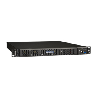
Advantech sky-8100 User Manual (152 pages)
1U CARRIER GRADE SERVER BASED ON PROCESSOR INTEL XEON-D SERIES
Brand:
Advantech
| Category:
Server
| Size: 6 MB
Table of Contents
Revision History
3
About this Manual
4
Copyright and Trademarks
4
Table of Contents
7
Chapter 1 Getting Started
16
Safety Introductions
17
Safety Precautions Per IEC704-1
17
Safety Precautions - Static Electricity
18
Unpacking
19
Table 1-1: Packaging List
19
Installation and Configuration
20
Rack Mounting
20
Figure 1-1: Mounting Ear Thread Holes
20
Figure 1-2: Mounting Ear Screws Inserted but Not Fastened yet
20
Powering on
21
Connecting to Monitor, Keyboard and Mouse
21
Connecting to the Serial Console
21
Figure 1-3: Putty Session Configuration
22
Figure 1-4: Putty Serial Configuration
23
Figure 1-5: Putty Keyboard Settings
23
Figure 1-6: Putty Colour Settings
24
Figure 1-7: BIOS POST Screen
24
Installing an os
25
Pre-Installed Reference os
25
Installing And/Or Boot an os from a USB Key
25
Installing an os Via Network Boot
26
Booting an os Via Network Boot
27
Table 1-2: PXE BIOS Options
27
Getting Help: Technical Support and Assistance
28
Chapter 2 Product Specification
29
Overview
30
Figure 2-1: Carrier Grade Server SKY-8100
30
SKY-8100 System Architecture
31
Figure 2-2 SKY-8100 System Architecture
31
SKY-8100 Board List
32
SKY-8100MB Hardware Specification
32
Table 2-1: PCBA List for SKY-8100 System
32
Table 2-2: Major Specification of SKY-8100MB
32
SKY-8100MB Hardware Functions
33
Table 2-3: Summary of SKY-8100MB
33
Product Versions
34
Table 2-4: Available Product Versions
34
Technical Specifications
35
System Dimensions
35
Regulatory Compliance
35
Safety
35
Figure 2-3: System Dimensions
35
Table 2-5: Applicable Safety Regulations
35
Electromagnetic Compatibility
36
CE Mark
36
Table 2-6: Applicable EMC Regulations
36
Block Diagram
37
Figure 2-4: SKY-8100 Block Diagram
37
Processor(S)
38
Soc Feature Details
38
Table 2-7: Xeon-D Skus for Communications Infrastructure
38
DDR4 Memory System
39
Figure 2-5: DIMM and CPU Location
39
Table 2-8: Supported Memory Configurations
39
DDR4 DIMM Type and Configuration Priorities
40
Table 2-9: Broadwell-DE Supported DIMM Types Table
40
DDR4 DIMM Population Configurations
41
Table 2-10: DIMM Configurations Table for Two DIMM Socket Per Channel
41
Table 2-11: DIMM Configurations Table for One DIMM Socket Per Channel
41
Broadwell-DE DDR4 DIMM Location and Smbus Mapping
42
Figure 2-6: Broadwell-DE DDR4 DIMM Location on SKY-8100MB
42
Table 2-12: H/W and Device Address for Two DIMM Socket Per Channel
42
Validated Modules
43
Usb
43
Table 2-13: Validated Dimms
43
Table 2-14: USB Ports
43
Figure 2-7: Broadwell-DE USB3.0 Block Diagram for SKY-8100MB
44
Figure 2-8: Broadwell-DE USB2.0 Block Diagram for SKY-8100MB
44
Universal Serial Bus (USB) 2.0 Controllers
44
Universal Serial Bus (USB) 3.0 Controllers
44
Serial ATA(SATA) Controller
45
Figure 2-9: Broadwell-DE SATA Block Diagram for NAMB-3260MB
45
Figure 2-10: M.2 SSD
45
Table 2-15: SATA Ports
45
Figure 2-11: M.2 Ssds' Locations
46
Table 2-16: Validated M.2 Ssds
46
PCI Express (Pcie) Gen3 Expansion
47
Figure 2-13: Pcie Cages (Top View)
47
Figure 2-14: Broadwell-DE Pcie Gen3 Expansion Gold Finger Location on
48
PCI Express Gen2 Root Port
49
Low Pin Count (LPC) Interface
49
Serial Peripheral Interface (SPI)
49
UART Interface
49
Figure 2-15: Broadwell-DE Pcie Express Gen2 Block Diagram for SKY-8100MB
49
Figure 2-16: Broadwell-DE LPC Block Diagram for NAMB-3260MB
49
System Management Bus (Smbus 2.0)
50
Figure 2-17: SKY-8100 System Smbus Block Diagram
50
Integrated 10Gbe Controller
51
Figure 2-18: Broadwell-DE Integrated 10Gbe Logical Block Diagram
51
Dual 15 Gbps PHY - Inphi CS4227
52
SFI Interface Feature Details
52
Figure 2-19: Broadwell-DE SFP+ Implementation with Inphi CS4227 Block Diagram
52
Quadl Port Gbe LAN Controller - Intel I350
53
Figure 2-20: Broadwell-DE LAN Implementation with Intel I350 Block Diagram
53
SKY-8100 Manual V05 20161229 Copyright 2016 Advantech Co. Ltd. All Rights Reserved
53
Gbe LAN Controller - Intel I210
54
Figure 2-21: Broadwell-DE LAN Implementation with Intel I210 Block Diagram
54
Hardware Monitor Chip - Nuvoton NCT7904D
55
System Hardware Specificatoin
56
Figure 2-22: Front View of SKY-8100 (Cover Closed)
56
Figure 2-23: Front View of SKY-8100 (Cover Opened)
56
Figure 2-24: Front Panel
57
Table 2-17: Front Panel List
57
Figure 2-25: Status Leds (Front Panel)
58
Status Leds
58
Table 2-18: Status Leds
58
Front Panel
57
Rear Panel
60
Ethernet Connectors
60
Figure 2-26: Rear Panel
60
Figure 2-27: RJ-45 Leds (Rear Panel)
60
Table 2-19: Rear Panel List
60
Table 2-20: RJ-45 Leds
61
Bios
62
Password Protection
62
BIOS Defaults
62
Pcie Tree
62
Table 2-21: Pcie Devices
63
Advanced Platform Management
64
Hardware and Environmental Monitoring
64
Figure 2-28: Thermal Sensor Locations
65
Table 2-22: Thermal Sensors
65
Thermal Management
66
Figure 2-29: System Airflow and Fans
66
Power Supplies
67
Ac Psu
67
Figure 2-30: AC PSU Details
67
DC Psu
68
Protection
68
Table 2-24: DC PSU Details
68
Table 2-25: PSU Protection Warning and Critical Levels
68
Product Labelling
69
Table 2-27: Product Labels
69
Electronic Label: FRU EEPROM
70
Advanced Platform Features
71
Intrusion Detection
71
Watchdogs
71
Available Accessories and Related Products
71
Accessories
71
Table 2-28: Accessories
71
Chapter 3 BIOS & BMC
72
BIOS Setup Menu
73
Figure 3-1: BIOS POST Screen
73
Figure 3-2: BIOS Setup Screen Organization
74
Figure 3-3: BIOS Setup Main Screen
74
Setting System Time and Date
75
Table 3-1: BIOS Setup: Main Menu
75
Main Setup Menu
74
Platform Setup Menu
76
Serial Console
76
Trusted Computing
76
Figure 3-4: Platform Setup: Main Screen
76
Figure 3-5: Platform Setup: Security Screen
76
USB Configuration
77
Figure 3-6: Platform Setup: USB Configuration Menu
77
Table 3-2: Trusted Computing Menu
77
Table 3-3: USB Configuration Menu
78
Figure 3-7: Security Menu
79
Security Setup
79
Figure 3-8: Save & Exit Menu
80
Save & Exit Menu
80
Table 3-4: Save & Exit Menu Options
80
Firmware Upgrades
81
BMC Application
82
BMC Bootloader
83
Figure 3-9: BMC Application Upgrade
83
Figure 3-10: BMC Bootloader Upgrade
84
Bios
85
Figure 3-11: BIOS Upgrade
85
Bios Nvram
86
Figure 3-12: Check Active BIOS Version
86
Figure 3-12: BIOS NVRAM Upgrade
86
Figure 3-13: Check Active BIOS NVRAM Version
87
Chapter 4 Setting up
88
Installing Components
89
Server Slide
89
Figure 4-1: Standard Retail Packaging
89
Figure 4-2: Remove the Inner Chassis
90
Figure 4-3: Mount the Inner Chassis
90
Mount the Chassis (Inner) Member to the Chassis
90
Remove the Chassis (Inner) Member
90
Attach the Cabinet (Outer) Member to the Rail
91
Figure 4-4: Install the Bracket
91
Figure 4-5: Uninstall the Bracket
91
Figure 4-6: Mount the Chassis into the Cabinet
92
Mount the Chassis into the Cabinet
92
Figure 4-7: SB Tool-Less Bracket
93
Hard Drive
94
Hard Drive Replacement
94
Figure 4-8: Hard Disk Drives
94
Figure 4-9: Hard Driver Replacement
94
Figure 4-10: Hard Driver Replacement
94
Open the HDD Tray
95
SAS Hard Drive Carriers
95
Figure 4-11: Unlocked the HDD Tray
95
Figure 4-12: Open the HDD Tray
95
Figure 4-13: SAS Hard Drive Tray Component
95
PCI Riser Card
96
Riser Card Replacement
96
Figure 4-14: Riser Card Replacement
96
Dismounting Cards from the Pcie Component
97
Reassembling the Pcie Component into the Chassis
97
Figure 4-15: Dismounting Cards from the Pcie Component
97
Server Board
98
Memory Card Installation
98
Figure 4-16: Server Board Layout
98
Figure 4-17: (A) Install Memory Card (B) Uninstall Memory Card
98
Msata Card Installation
99
Filter Replacement
99
Figure 4-18: Install Msata Card
99
Figure 4-19: Filter Replacement 1
99
Figure 4-20: Filter Replacement 2
99
Fan Replacement
100
Figure 4-21: Filter Replacement 3
100
Figure 4-22: Filter Replacement 4
100
Figure 4-23: Fan Replacement 1
100
Figure 4-24: Fan Replacement 2
101
Figure 4-25: Fan Replacement 3
101
Figure 4-26: Fan Replacement 4
101
Power Module Replacement
102
Figure 4-27: Power Module Replacement
102
Replacing Frus
103
Air Filter
103
Figure 4-28: Air Filter
103
Figure 4-29: Air Filter Assembly
103
PSU Modules
104
Figure 4-30: PSU Modules
104
Disk Drives
105
Hdd
105
Msata SSD
105
Figure 4-31: 2.5" HDD
105
RTC Battery
106
Figure 4-32: Unlocking the Battery
106
Dimms
107
Fan Module
107
Figure 4-33: FAN Module
107
Appendix A Connector Pinout and LED Information
109
Jumpers
110
Figure A-1: Jumpers on the Server Board
110
Table A-1: Server Board Assemblies List
111
Connectors
112
LOM Connectors (CN5)
112
Figure A-2: LOM Connector (CN5)
112
Table A-2: LOM Connector (CN5) Pin Definitions
112
The CPLD JTAG Connectors (CN7)
116
Figure A-3: CPLD JTAG Connector (CN7)
116
Table A-3: CPLD JTAG Connector (CN7) Pin Definitions
116
The RJ-45 Console Connectors (CN9)
117
Figure A-4: RJ-45 Console Connector (CN9)
117
Table A-4: RJ-45 Connector (CN9) Pin Definitions
117
The 2X10-Pin Front Panel Connectors (CN11)
118
Figure A-5: 2X10-Pin Front Panel Connector (CN11)
118
Table A-5: 2X10-Pin Front Panel Connector (CN11) Pin Definitions
118
The 2X7-Pin Front Panel Connectors (CN14)
120
Figure A-6: 2X7-Pin Front Panel Connector (CN14)
120
Table A-6: 2X7-Pin Front Panel Connector (CN14) Pin Definitions
120
Power Button Signal Connectors (CN16)
121
Figure A-7: Power Button Signal Connector (CN16)
121
Table A-7: Power Button Connector (CN16) Pin Definitions
121
The +12V CPU ATX 4-Pin Power Connectors (ATX12V1)
122
Figure A-8: Power Connector (ATX12V1)
122
Table A-8: Power Connector (ATX12V1) Pin Definitions
122
Pin Headers
123
TPM Module / Port-80 Pin Header (CN6)
123
Figure A-9 : TPM Module/Port-80 (CN6)
123
Table A-9: TPM Module/Port-80 (CN6) Pin Definitions
123
External Fan Control Board Pin Header (CN20)
125
Figure A-10: External Fan Control Board (CN20)
125
Table A-10: External Fan Control Board (CN20) Pin Definitions
125
Pin Header Upgrade for the CPU Power PWM Controller (CN21)
126
Figure A-11: CPU Power PWM Controller Upgrade (CN21)
126
Table A-11: CPU Power PWM Controller Upgrade (CN21) Pin Definitions
126
Pin Header Upgrade for the CS4227 Chipset (L2C1)
127
Figure A-12: CS4227 Chipset Upgrade (I2C1)
127
Table A-12: CS4227 Chipset Upgrade (I2C1) Pin Definitions
127
USB3.0 Pin Header (USB1)
128
Figure A-13: USB3.0 (USB1)
128
Table A-13: USB3.0 (USB1) Pin Definitions
128
Clear CMOS Pin Header (CLS_CMOS1)
130
Figure A-14: Clear CMOS (CLS_CMOS1)
130
Table A-14: Clear CMOS (CLS_CMOS1) Pin Definitions
130
Table A-15: Jumper Settings for the Clear CMOS
130
Me Mode Select Pin Header (ME_MODE1)
131
Figure A-15 : ME Mode Select (ME_MODE1)
131
Table A-16: ME Mode Select (ME_MODE1) Pin Definitions
131
Table A-17: ME Mode Select (ME_MODE1) Pin Pairing
131
Switch
132
LAN Port Reset Switch (SW2)
132
Figure A-16: LAN Port Reset (SW2)
132
Table A-18: LAN Port Reset (SW2) Pin Definitions
132
Table A-19: LAN Port Reset (SW2) Switch Setting
132
Appendix B BIOS Post Code
133
Table B-1: BOIS POST Codes
134
Appendix C Power Supply Specification
141
Redundant 650W AC PSU
142
Current Drawn from AC Source
142
Max Inrush Current Drawn from AC Source
142
Power Supplies be Configured for Hot Failover
142
Table C-1: Maximum Input Current
142
Table C-2: 650W AC Power Supply Specification
143
Redundant 650W DC PSU
144
Table C-3: 650W DC Power Supply Specification
144
Advertisement
Advertisement
Related Products
Advantech SKY-8132S-11
Advantech SKY-8101
Advantech SKY-8101D
Advantech SKY-8101DAS-0000E
Advantech SKY-8132S
Advantech SKY-8134DU
Advantech SKY-8201LAS-0020E
Advantech SKY-8232DV2
Advantech SKY-8232D
Advantech SKY-8260SAS-A0000
Advantech Categories
Motherboard
Computer Hardware
Desktop
Network Router
Touch Panel
More Advantech Manuals
Login
Sign In
OR
Sign in with Facebook
Sign in with Google
Upload manual
Upload from disk
Upload from URL