Sign In
Upload
Manuals
Brands
Advantech Manuals
Server
SKY-8101
Advantech SKY-8101 Manuals
Manuals and User Guides for Advantech SKY-8101. We have
1
Advantech SKY-8101 manual available for free PDF download: User Manual
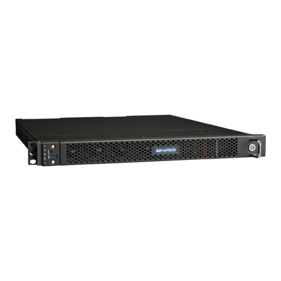
Advantech SKY-8101 User Manual (138 pages)
COMPACT 1U HIGH PERFORMANCE SERVER BASED ON INTEL XEON PROCESSOR SCALABLE FAMILY
Brand:
Advantech
| Category:
Server
| Size: 4.1 MB
Table of Contents
Table of Contents
7
Chapter 1 Getting Started
14
Safety Instructions
15
Safety Precautions Per IEC704-1
15
Safety Precautions - Static Electricity
16
Unpacking
17
Table 1-1: Packaging List
17
Installation and Configuration
18
Rack Mounting
18
Figure 1-1: Mounting Ear Screws Inserted Location
18
Chassis Slide Rail Installation
19
Powering on
21
Connecting to Monitor, Keyboard and Mouse
22
Connecting to the Serial Console
22
Figure 1-3: Putty Session Configuration
23
Figure 1-4: Putty Serial Configuration
24
Figure 1-5: Putty Keyboard Settings
24
Figure 1-6: Putty Colour Settings
25
Figure 1-7: BIOS POST Screen
25
Installing an os
26
Pre-Installed Reference os
26
Installing And/Or Boot an os from a USB Key
26
Installing an os Via Network Boot
27
Booting an os Via Network Boot
27
Table 1-2: PXE BIOS Options
27
Figure 1-13: Booting the Client with Legacy Option Screen_2
29
Figure 1-14: Booting the Client with UEFI Option Screen_1
30
Figure 1-15: Booting the Client with UEFI Option Screen_2
30
Getting Help: Technical Support and Assistance
31
Chapter 2 Product Specification
32
Overview
33
Figure 2-1: Carrier Grade Server SKY-8101S
33
Product Versions
34
Table 2-1: Available Product Versions
34
Technical Specifications
35
SKY-8101S System Specification
35
System Dimensions
36
Figure 2-2: System Dimensions
36
Detail Description
37
Front Elements
37
Leds Details
37
Figure 2-3: Front Panel
37
Table 2-2: Front Elements
37
Figure 2-4: Status Leds (Front Panel)
38
Table 2-3: Status Leds
38
Front Button Details
39
Figure 2-5: Front Buttons
39
Table 2-4: Front Buttons
39
Fan Module Details
40
Figure 2-6: Fan Module
40
Table 2-5: Fan Module
40
Disk Bay Details
41
Figure 2-7: Disk Bays
41
Table 2-6: Disk Bay
41
Figure 2-8: Disk Tray
42
Table 2-7: Disk Tray
42
Rear Panel
43
Figure 2-9: System Rear View
43
Table 2-8: Rear Panel List
43
Pcie Card Details
44
Figure 2-10: Pcie Card Slot Details
44
Table 2-9: Pcie Card Slot Details
44
Inside the System
45
Figure 2-11: System Top View (Cover Removed)
45
Table 2-10: Rear Panel List
45
System Block Diagram
46
Processor(S)
46
Figure 2-12: Block Diagram
46
Processor Feature Details
47
Memory
47
Memory Sub-System
47
Table 2-11: Intel® Xeon® Processor Skus for Communications Infrastructure
47
DDR4 DIMM Location and Smbus Mapping
49
Validated Memory Modules
49
Figure 2-13: DIMM and CPU Location
49
Table 2-12: Intel® Xeon® Processor DDR4 DIMM Smbus Address List
49
Table 2-13: Validated Dimms
49
Quickassist Accelerator
50
Network Interface (on Board)
51
Pcie Expansion
51
Figure 2-15: Pcie Cages (Top View)
51
Tpm
53
Mass Storage
53
Bios
53
Password Protection
53
Figure 2-18: Location of Msata Sockets
53
BIOS Defaults
54
Pcie Tree
54
Advanced Platform Management
54
Hardware and Environmental Monitoring
54
Thermal Management
56
Figure 2-20: System Airflow and Fans
56
Power Supplies
57
Ac Psu
57
Figure 2-21: AC PSU Details
57
Table 2-14: AC PSU Details
57
DC Psu
58
Figure 2-22: DC PSU Details
58
Table 2-15: DC PSU Details
58
Advanced Platform Features
60
Intrusion Detection
60
Watchdogs
60
Available Accessories and Related Products
60
Accessories
60
Spare Parts
60
Table 2-16: Accessories
60
Related Products
61
Table 2-17: Spare Parts
61
Table 2-18: Related Products
61
Chapter 3 Configuration and Service
62
Jumper Settings
63
BIOS Setup Menu
63
Figure 3-1: BIOS POST Screen
63
Main Setup Menu
64
Figure 3-2: BIOS Setup Screen Organization
64
Figure 3-3: BIOS Setup Main Screen
64
Setting System Time and Date
65
Table 3-1: BIOS Setup: Main Menu
65
Platform Setup Menu
66
Serial Console
66
Figure 3-4: Platform Setup: Main Screen
66
Figure 3-5: Platform Setup: Serial Console Menu
67
Table 3-2: Serial Console Menu
67
USB Configuration
68
Figure 3-6: Platform Setup: USB Configuration Menu
68
Table 3-3: USB Configuration Menu
68
Trusted Computing (if TPM1.2 Present)
69
Figure 3-7: Platform Setup: Trusted Computing(TPM1.2)
69
Trusted Computing (if TPM2.0 Present)
70
Figure 3-8: Platform Setup: Trusted Computing(TPM2.0)
70
Table 3-4: Trusted Computing Menu (TPM1.2)
70
Table 3-5: Trusted Computing Menu (TPM2.0)
71
Virtualization
72
Platform Management
72
Figure 3-9: Platform Setup: Virtualization
72
Table 3-6: Virtualization
72
Figure 3-10: Platform Setup: Platform Management
73
Table 3-7: Platform Management
73
Hardware Setup
75
CPU Configuration
75
Figure 3-11: Hardware Setup
75
Figure 3-12: Hardware Setup: CPU Configuration
75
Table 3-8: CPU Configuration
76
Northbridge
77
Figure 3-13: Hardware Setup: Northbridge
77
Table 3-9: Northbridge
77
Figure 3-14: Hardware Setup: DIMM Information
78
Figure 3-15: Hardware Setup: PCI Express Ports Configuration
79
Table 3-10: PCI Express Ports Configuration
79
Southbridge
80
Figure 3-16: Hardware Setup: Southbridge
80
Table 3-11: Southbridge
80
Figure 3-17: Hardware Setup: SATA Configuration
81
Table 3-12: SATA Configuration
81
Figure 3-18: Hardware Setup: USB Configuration
83
Table 3-13: USB Configuration
83
Figure 3-19: Hardware Setup: ACPI Settings
84
Table 3-14: ACPI Settings
84
Nvme Configuration
85
Figure 3-20: Hardware Setup: Runtime Error Logging
85
Figure 3-21: Hardware Setup: Nvme Configuration
85
Table 3-15: Runtime Error Logging
85
Intel Virtual RAID on CPU
86
Figure 3-22: Hardware Setup: Intel VROC
86
Server Management Setup
87
Figure 3-23: Server Management Setup
87
Table 3-16: Server Management Setup
87
Security Setup
88
Figure 3-24: Security Menu
88
Post & Boot Menu
89
Figure 3-25: Post & Boot Menu
89
Table 3-17: Post & Boot Menu
89
CSM16 Configuration
90
Figure 3-26: Post & Boot Menu: CSM16 Configuration
90
Table 3-18: CSM16 Configuration
90
Compatibility Support Module (CSM) Configuration
91
Figure 3-27: Post & Boot Menu: CSM Configuration
91
Table 3-19: CSM Configuration
91
Save & Exit Menu
92
Figure 3-28: Save & Exit Menu
92
Table 3-20: Save & Exit Menu Options
92
Installing Components
95
Removing the Top Cover
95
Figure 3-13: Slide Top Cover Back
95
Reinstalling the Top Cover
96
Pcie Card Installation
96
Figure 3-16: Pcie Card Cage Assembly
97
Figure 3-16: Pcie Card Cage Assembly
98
Disk Installation
99
HDD/SSD Drives
99
Figure 3-20: Unlocking the Disk Tray
99
Figure 3-21: Opening the Disk Tray
99
Figure 3-22: Removing the Disk Tray
99
Ssd
100
Figure 3-23: Mounting the Drive in the Disk Tray
100
Memory Installation
101
Figure 3-25: M.2 SSD Installation
101
Figure 3-28: Opening DIMM Latches
101
Figure 3-29: DIMM Key Alignment
101
Figure 3-30: DIMM Insertion into Slide Rails
102
Figure 3-31: Seating the DIMM in the Socket
102
CPU Installation
103
Firmware Upgrades
104
Replacing Frus
104
Air Filter
105
PSU Modules
105
Figure 3-32: Air Filter Assembly
105
Disk Drives
106
Hdd
106
Ssd
106
Dimms
106
Figure 3-34: Unlocking and Removing a DIMM
107
Chapter 4 Tips, Tricks and Troubleshooting
108
Appendix A Connector Pinout and LED Information
110
Figure A-1: Micro USB (Micro-B), Connector for Console Port
111
Table A-1: Micro USB (Micro-B), Connector Pin Assignment
111
Figure A-2: USB Type a Connector
112
Table A-2: USB 3.0 Type a Connector Pin Assignment or Pin Assignment
112
Figure A-3: Displayport Connector
113
Table A-3: Displayport Connector Pin Assignment
113
Figure A-4: SFP+ Connector
115
Table A-4: SFP+ Connector Pin Assignment
115
Table A-5: SFP+ Connector LED Indication
116
Figure A-5: RJ45 10/100/1000Base-T Connector
117
Table A-6: RJ45 10/100/1000Base-T Connector Pin Assignment
117
Table A-7: RJ45 Connector LED Indication
117
Appendix B BIOS POST Code
118
Table B-1: BOIS POST Codes
119
Appendix C Power Supply Specification
126
Table C-1: 700W AC Power Supply Specification
127
Table C-2: 600W DC Power Supply Specification
129
Appendix D Declaration of Conformity
131
Appendix E Warranty and RMA
133
Appendix F Glossary
135
Advertisement
Advertisement
Related Products
Advantech sky-8100
Advantech SKY-8132S-11
Advantech SKY-8101D
Advantech SKY-8101DAS-0000E
Advantech SKY-8132S
Advantech SKY-8201L Series
Advantech SKY-8201L1
Advantech SKY-8201L2
Advantech SKY-8201LAS-0010E
Advantech SKY-8201LAS-0020E
Advantech Categories
Motherboard
Computer Hardware
Desktop
Touch Panel
PCI Card
More Advantech Manuals
Login
Sign In
OR
Sign in with Facebook
Sign in with Google
Upload manual
Upload from disk
Upload from URL