Sign In
Upload
Manuals
Brands
Advantech Manuals
Server
SKY-8260SAS-A0000
Advantech SKY-8260SAS-A0000 Manuals
Manuals and User Guides for Advantech SKY-8260SAS-A0000. We have
1
Advantech SKY-8260SAS-A0000 manual available for free PDF download: User Manual
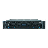
Advantech SKY-8260SAS-A0000 User Manual (116 pages)
Compact 2U Carrier Grade, High Performance Server based on AMD EPYC 7003/7002 Series Processors
Brand:
Advantech
| Category:
Server
| Size: 4.64 MB
Table of Contents
Table of Contents
6
Getting Started
13
Safety Instructions
14
Safety Precautions Per IEC704-1
14
Safety Precautions - Static Electricity
15
Unpacking
16
Table 1-1: Packaging List
16
Installation and Configuration
17
Chassis Slide Rail Installation
17
Powering on
19
Connecting to Monitor, Keyboard and Mouse
19
Connecting to the Serial Console
19
Figure 1-1: Putty Session Configuration
20
Figure 1-2: Putty Serial Configuration
20
Figure 1-3: Putty Keyboard Settings
21
Figure 1-4: Putty Colour Settings
21
Installing an os
22
Pre-Installed Reference os
22
Figure 1-5: BIOS POST Screen
22
Installing And/Or Boot an os from a USB Key
23
Installing an os Via Network Boot
23
Booting an os Via Network Boot
23
Table 1-2: PXE BIOS Options
24
Getting Help: Technical Support and Assistance
25
Product Specification
26
Overview
27
Figure 2-1: Carrier Grade Server SKY-8260S
27
Product Versions
28
Table 2-1: Available Product Versions
28
Technical Specifications
29
SKY-8260S System Specification
29
System Dimensions
30
Figure 2-2: System Dimensions
30
Detail Description
31
Front Elements
31
Figure 2-3: Front Panel
31
Table 2-2: Front Elements
31
Leds Details
32
Figure 2-4: Status Leds (Front Panel)
32
Table 2-3: Status Leds
32
Front Button Details
34
Fan Module Details
34
Figure 2-5: Front Buttons
34
Table 2-4: Front Buttons
34
Storage LED
35
Figure 2-6: Fan Module
35
Figure 2-7: Internal Storage LED
35
Table 2-5: Fan Module
35
Table 2-6: Internal Storage LED
35
Rear Panel
36
Figure 2-8: System Rear View
36
Table 2-7: Rear Panel List
36
Disk Bay Detail
37
Figure 2-9: Disk Bays
37
Figure 2-10: Disk Tray
37
Table 2-8: Disk
37
Table 2-9: Disk Tray
37
Inside the System
38
Figure 2-11: System Top View (Cover Removed)
38
Table 2-10: Internal System Components List
38
System Block Diagram
40
Processor(S)
40
Figure 2-12: Block Diagram
40
Table 2-11: AMD EPYC TM 7002 Series Processors Supported List
40
Processor Feature Details
41
Memory
41
Memory Sub-System
41
Table 2-12: AMD EPYC TM 7003 Series Processors Supported List
41
DDR4 DIMM Location and Smbus Mapping
42
Table 2-13: AMD EPYC TM Processor DDR4 DIMM Smbus Address List
42
Validated Memory Modules
43
Figure 2-13: DIMM and CPU Location
43
Table 2-14: Validated Dimms
43
Network Interface (on Board)
44
Pcie Expansion
44
Figure 2-14: Pcie Cages (Top View)
44
Tpm
45
Mass Storage
45
Internal Storage
45
Figure 2-15: Location of Msata Sockets
45
Figure 2-15: Location of Internal Storages
45
Bios
46
Password Protection
46
BIOS Defaults
46
Pcie Tree
46
Advanced Platform Management
46
Hardware and Environmental Monitoring
47
Thermal Management
47
Figure 2-16: System Airflow and Fans
48
Power Supplies
49
Ac Psu
49
Figure 2-17: AC PSU Details
49
Table 2-15: AC PSU Details
49
DC Psu
50
Figure 2-18: DC PSU Details
50
Table 2-16: DC PSU Details
50
Advanced Platform Features
52
Intrusion Detection
52
Watchdogs
52
Available Accessories and Related Products
53
Accessories
53
Spare Parts
53
Table 2-17: Accessories
53
Table 2-18: Spare Parts
53
Related Products
54
Table 2-19: Related Products
54
Configuration and Service
55
Jumper Settings
56
BIOS Setup Menu
56
Figure 3-1: BIOS POST Screen
56
Figure 3-2: BIOS Setup Screen Organization
57
Figure 3-3: BIOS Setup Main Screen
57
Table 3-1: Main Menu
58
Figure 3-4: Platform Setup: Main Screen
59
Figure 3-5: Platform Setup: Serial Console Menu
59
Table 3-2: Serial Console Menu
60
Figure 3-6: Platform Setup: USB Configuration Menu
61
Table 3-3: USB Configuration Menu
61
Figure 3-7: Platform Setup: Trusted Computing (TPM2.0)
62
Table 3-4: Trusted Computing Menu (TPM2.0)
62
Figure 3-8: Platform Setup: Virtualization
63
Table 3-5: Virtualization
63
Figure 3-9: Platform Setup: Platform Management
64
Table 3-6: Platform Management
64
Figure 3-10 Hardware Setup
65
Figure 3-11 Hardware Setup: CPU Configuration
65
Figure 3-12: Hardware Setup: DIMM Configuration
66
Table 3-7: CPU Configuration
66
Figure 3-13: Hardware Setup: Southbridge
67
Table 3-8: Southbridge
67
Figure 3-14: Hardware Setup: SATA Configuration
68
Table 3-9: SATA Configuration
68
Figure 3-15: Hardware Setup: ACPI Settings
69
Figure 3-16: Hardware Setup: Runtime Error Logging
69
Table 3-10: ACPI Setting
69
Table 3-11: Runtime Error Logging
69
Figure 3-17: Hardware Setup: Nvme Configuration
70
Figure 3-18: Sever Management Setup
70
Table 3-12: Server Management Setup
71
Figure 3-19: Security Menu
72
Figure 3-20: Post and Boot Menu
73
Table 3-13: Post & Boot Menu
73
Figure 3-21: Post and Boot Menu: CSM Configuration
74
Table 3-14: CSM Configuration
74
Figure 3-22: Save & Exit Menu
75
Table 3-15: Save & Exit Menu Options
75
Installing Components
77
Removing the Top Cover
77
Figure 3-23: Slide Top Cover Back
77
Reinstalling the Top Cover
78
Middle Bar Installation
78
4Pcie Card Installation
78
Figure 3-24: Middle Bar Installation
78
Figure 3-25: Pcie Card Cage Assembly: Thumb Screw Location
79
Figure 3-26: Pcie Card Cage Assembly: Pcie Cage Latch
79
Figure 3-27: Pcie Card Cage Assembly: Pcie Slot Latch
80
Figure 3-28: Pcie Card Cage Assembly: Connect Power Cable
80
Figure 3-29: Pcie Card Cage Assembly: Pcie Cage Guide Pins
80
5Disk Installation
81
HDD/SSD Drives
81
Figure 3-30: Pcie Card Cage Assembly: External Power Adapter
81
Figure 3-31: Opening the Disk Tray
81
Ssd
82
Figure 3-32: Removing the Disk Tray
82
Figure 3-33: Mounting the Drive in the Disk Tray
82
Memory Installation
83
Figure 3-34: M.2 SSD Installation
83
Figure 3-35: Opening DIMM Latches
83
Figure 3-36: DIMM Key Alignment
83
Figure 3-37: DIMM Insertion into Slide Rails
84
Figure 3-38: Seating the DIMM in the Socket
84
CPU Installation
85
Figure 3-39: AMD CPU Installation
85
Firmware Upgrades
86
Replacing Frus
86
Air Filter
86
PSU Modules
87
Figure 3-40: Air Filter Assembly
87
Disk Drives
88
Hdd
88
Ssd
88
Dimms
88
Figure 3-41: Unlocking and Removing a DIMM
89
Tips, Tricks and Troubleshooting
90
Connector Pinout and LED Information
91
Console Port
92
Figure A-1: RJ45 Console Connector
92
Table A-1: Console Connector Pin Assignment
92
USB 3.0/2.0 Type a Connectors
93
Figure A-2: USB Type a Connector
93
Table A-2: USB 3.0 Type a Connector Pin Assignment or Pin Assignment
93
Table A-3: USB 2.0 Type a Connector Pin Assignment or Pin Assignment
94
VGA Connector
95
Figure A-3: Displayport Connector
95
Table A-4: Displayport Connector Pin Assignment
95
RJ45 10/100/1000BASE-T Ports
96
Connector Pinout
96
LED Definition
96
Figure A-5: RJ45 10/100/1000Base-T Connector
96
Table A-5: RJ45 10/100/1000Base-T Connector Pin Assignment
96
Table A-6: RJ45 Connector LED Indication
96
RJ45 Management Ports
97
Figure A-6: RJ45 Management Port Connector
97
Table A-7: RJ45 Management Port Connector Pin Assignment
97
BIOS POST Code
98
Table B-1: BOIS POST Codes
99
Power Supply Specification
104
Redundant 1200W AC PSU
105
Table C-1: 1200W AC Power Supply Specification
105
Redundant 800W DC PSU
107
Table C-2: 800W DC Power Supply Specification
107
Declaration of Conformity
109
Warranty and RMA
111
Glossary
113
Advertisement
Advertisement
Related Products
Advantech SKY-8260S
Advantech SKY-8260SAS-D0000
Advantech SKY-8201L Series
Advantech SKY-8201L1
Advantech SKY-8201L2
Advantech SKY-8201LAS-0010E
Advantech SKY-8201LAS-0020E
Advantech SKY-8232D
Advantech SKY-8232DV2
Advantech SKY-8232DV2 2U
Advantech Categories
Motherboard
Computer Hardware
Desktop
Touch Panel
Network Router
More Advantech Manuals
Login
Sign In
OR
Sign in with Facebook
Sign in with Google
Upload manual
Upload from disk
Upload from URL