
Subscribe to Our Youtube Channel
Related Manuals for AMX SDX-510M-DX


Summary of Contents for AMX SDX-510M-DX
-
Page 1: Instruction Manual
Instruction Manual - Solecis Digital Switchers Instruction Manual ® Solecis Digital Switchers SDX-410-DX SDX-510M-DX SDX-810-DX L a t e s t R e l e a s e : 1 / 2 9 / 2 0 1 5 Digital Switchers... - Page 2 AMX is not responsible for products returned without a valid RMA number. AMX is not liable for any damages caused by its products or for the failure of its products to perform. This includes any lost profits, lost savings, incidental damages, or consequential damages.
-
Page 3: Important Safety Instructions
Important Safety Instructions Important Safety Instructions Please adhere to all of the following safety instructions: 1. Read the instructions. Keep the instructions. Heed all warnings. Follow the instructions. Do not use this apparatus near water. Clean this apparatus only with a dry cloth. Do not block any ventilation openings. - Page 4 Important Safety Instructions Instruction Manual - Enova DVX-3150HD/3155HD/3156HD All-in-One Presentation Switcher...
-
Page 5: Table Of Contents
PROGRAM Port......................18 USB (SDX-510M-DX only)....................19 Power ........................19 INPUT POWER Connector (SDX-410-DX and SDX-810-DX only)........19 AC Power Connector (SDX-510M-DX only) ..............19 Wiring Specifications ..................21 Overview ........................ 21 Port Pinouts and Wiring Specifications ..............21 HDMI INPUTS........................ 21 DVI Pinout for DVI-to-HDMI Cable Adapter ................ - Page 6 Solecis Digital Switchers - Firmware Files ............... 35 Before You Start ..................... 35 Verifying the Current Firmware Version ..............35 Downloading the Latest Firmware Files from www.amx.com ......... 36 Upgrading Firmware via NetLinx Studio..............36 Programming ....................39 Overview ........................ 39 SEND_COMMANDS....................
- Page 7 Table of Contents AUDOUT_FORMAT ........................40 ?AUDOUT_MUTE ........................40 Video SEND_COMMANDs..................41 VI<input>O<output> ........................ 41 ?VIDIN_AUTO_SELECT ......................41 VIDIN_AUTO_SELECT........................ 41 AUDOUT_MUTE ........................41 CI<input>O<output> ........................ 41 ?VIDIN_EDID ..........................42 VIDIN_EDID ..........................42 ?VIDIN_EDID_AUTO........................42 VIDIN_EDID_AUTO........................42 ?VIDIN_FORMAT ........................42 ?VIDIN_HDCP..........................42 VIDIN_HDCP..........................
- Page 8 Table of Contents DIPSWITCH ..........................48 EXIT ............................48 FACTORYFWIMAGE ......................... 48 GET CONFIG..........................49 GET CONNECTION........................49 GET DEVICE..........................49 GET DNS........................... 49 GET FRIENDLY.......................... 50 GET IP ............................50 GET LOCATION ........................50 GET SN ............................. 50 MSG [ON|OFF] .......................... 50 NDP UNBIND..........................
-
Page 9: Overview
DXLink and HDMI output. The SDX-410-DX provides four user connection points and the SDX-810-DX provides eight. The SDX-510M-DX provides five user connection points and includes three HDMI and two VGA video inputs. - Page 10 Power Connector: 2-pin 3.5mm Screw Retention Connector External, Required Optimal performance requires use of one of the following AMX power supplies (not included): • PSR4.4, 13.5 VDC, 4.4 A Power Supply with 3.5mm Phoenix Connector with Retention Screws (FG423-46) • PSN6.5, 13.5 VDC, 6.5 A Power Supply with (3) 3.5mm Phoenix Connectors (FG423-41)
- Page 11 Overview SDX-410-DX Specifications (Cont.) Front Connectors: Advanced (1) USB Mini-B Connector Configuration Interface: ID Pushbutton: (1) ID Pushbutton, can be used to assign the unit’s Device ID, switch between Static and Dynamic IP addressing modes, and reset the unit to factory defaults. Back Connectors: HDMI Input: (4) HDMI Type A Female Connectors...
- Page 12 HDCP Support: Supports AMX HDCP InstaGate Pro Technology When used with an AMX Digital Media Switcher the key support is up to 16 sinks per output, independent of source device. When used as a single point-to-point solution the key support is defined by the source device.
-
Page 13: Sdx-510M-Dx
Overview SDX-510M-DX The following table lists the specifications for the SDX-510M-DX: SDX-510M-DX Specifications General: Dimensions (HWD): 1 11/16" x 10" x 6 7/8" (43.18 mm x 254 mm x 175.26 mm) Weight: 3.5 lb (1.6 kg) Mounting Options: Compatible with V Style Module Surface Mount or V Style Rack Mount Compatible AMX Enova •... - Page 14 Overview SDX-510M-DX Specifications (Cont.) Active Power Requirements: Voltage, AC (Typical): 110-240VAC, 47-63 Hz Power Consumption 48 W (Max): Power Connector: IEC Power Cord Connector 100-240 VAC 47-63 Hz DXLink Power: Supplies power to a DXLink Twisted Pair RX, when used in point-to-point applications...
- Page 15 Overview SDX-510M-DX Specifications (Cont.) Controls & Indicators: AxLink Keypad Port: (1), 4-pin 3.5 mm captive-wire connector, provides data and power to up to 2 external AxLink Keypads AxLink Indicator: (1) AxLink Keypad LED (green) indicates the state of the AxLink Keypad port LINK/ACT Indicator: (1) LED (green), lights when the Ethernet cable is connected and an active link is established.
- Page 16 HDCP Support: Supports AMX HDCP InstaGate Pro Technology When used with an AMX Digital Media Switcher the key support is up to 16 sinks per output, independent of source device. When used as a single point-to-point solution the key support is defined by the source device.
-
Page 17: Sdx-810-Dx
For more details and helpful cabling information, reference the white paper titled Cabling for Success with DXLink, or contact your AMX representative. Active Power Requirements: Twisted Pair Cable Up to 328 ft. - Page 18 SDX-810-DX Specifications (Cont.) Power Supply: External, Required Optimal performance requires use of one of the following AMX power supplies (not included): • PSR4.4, 13.5 VDC, 4.4 A Power Supply with 3.5mm Phoenix Connector with Retention Screws (FG423-46) • PSN6.5, 13.5 VDC, 6.5 A Power Supply with (3) 3.5mm Phoenix Connectors (FG423-41)
- Page 19 HDCP Support: Supports AMX HDCP InstaGate Pro Technology When used with an AMX Digital Media Switcher the key support is up to 16 sinks per output, independent of source device. When used as a single point-to-point solution the key support is defined by the source device.
- Page 20 Overview Instruction Manual - Solecis Digital Switchers...
-
Page 21: Device Connectors
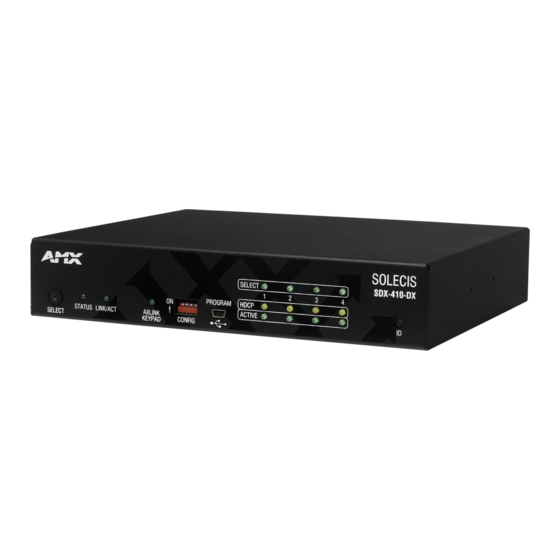
This chapter provides functional details for each item on the front and rear panel of the Solecis Digital Switchers. See the Wiring Specifications section on page 21 for information on wiring connectors for individual ports. FIG. 2 displays the front panels of the SDX-410-DX, SDX-510M-DX, and SDX-810-DX: FIG. 2 Solecis Digital Switchers front panels FIG. -
Page 22: Controls And Indicators
Device Connectors Controls and Indicators The following sub-sections describe each component on the front panel of the switcher. Refer to FIG. 2 on page 13 for the component layout of the front panel. SELECT Pushbutton Press the SELECT pushbutton to manually switch the input routed to the output. Each press switches to the next input in order, or if the last input is currently selected, switches to the first input. -
Page 23: Axlink Keypad Port (4-Pin Captive-Wire)
AXLINK KEYPAD Port (4-pin captive-wire) The AXLINK KEYPAD port allows the switcher to provide power and data to up to two AMX AxLink Keypads. AxLink functionality requires a NetLinx Master to be present on the connected network. The AXLINK KEYPAD LED indicating activity on the port is located on the front panel of the device. -
Page 24: Id Pushbutton
(The SDX-510M-DX features two sets of Dual External buttons. See the GROUP INPUTS (SDX-510M-DX only) section on page 17 for more information.) With a single button module connected to one of these ports, you can press the button on the module to send a button press event to a connected Master. You can use this function to have the Master send a command back to the switcher to execute a switch. -
Page 25: Inputs And Outputs
The SDX-510M-DX has two sets of groups in which the first external button LED control connector is used to cycle through the inputs within a particular group. On the SDX-510M-DX, HDMI INPUT 1 is always the first input on both groups. -
Page 26: Outputs
Ethernet cables. The port LEDs show communication activity, connection status, speeds, and mode information. The SDX-410-DX and SDX-810-DX each feature two LAN OUT ports located on the back panel of the units. The SDX-510M-DX features three LAN OUT ports located on its front panel. -
Page 27: Usb (Sdx-510M-Dx Only)
USB (SDX-510M-DX only) The two type-A USB connectors on the front panel are used to connect peripheral devices to the SDX-510M-DX (FIG. 16). You can use the type-B USB connector to connect the switcher to a PC and emulate keyboard and mouse commands from a DXLink Receiver. - Page 28 Device Connectors Instruction Manual - Solecis Digital Switchers...
-
Page 29: Wiring Specifications
Wiring Specifications Wiring Specifications Overview This chapter provides the port pinouts and wiring specifications (when applicable) for each port on the front and rear panels of the Solecis Digital Switchers. Port Pinouts and Wiring Specifications The following sub-sections describe the wiring for each port on the SDX switchers. Refer to the Device Connectors section on page 13 for the component layout of the switchers. -
Page 30: Dvi Pinout For Dvi-To-Hdmi Cable Adapter
Wiring Specifications DVI Pinout for DVI-to-HDMI Cable Adapter The pinout in FIG. 20 is for DVI-to-HDMI cable adapters which can be used with the modules when a DVI-I signal is required. FIG. 20 DVI pinout for DVI-to-HDMI cable adapter DVI Connector Pinout DVI Input Pin # Signal Name DVI Output Pin #... -
Page 31: Vga Input Ports
Wiring Specifications VGA INPUT Ports The SDX-510M-DX features two VGA input ports on the rear panel to route analog video from connected source input devices to the connected output devices. These ports support standard VGA cabling. FIG. 21 displays one of the VGA inputs. -
Page 32: Dxlink Output
DXLink devices or boards, including digitally transcoded analog video signals. The DXLink output supports HDCP. Note: The DXLink output on the SDX-510M-DX provides Power Over DXLink to compatible DXLink Receivers so they do not need local power at the display or projector. -
Page 33: Important Twisted Pair Cabling Requirements And Recommendations
Note: The AXLINK KEYPAD LED is located on the front panel of the SDX-410-DX and SDX-810-DX while the AxLink port itself is located on the rear panel. On the SDX-510M-DX, both the port and LED are located beside each other on the front panel. - Page 34 Wiring Specifications To use the 4-pin 3.5 mm mini-Phoenix (female) captive-wire connector for data communication and power transfer, the incoming PWR and GND cable from the 12 VDC-compliant power supply must be connected to the AxLink cable connector going to the switcher. FIG.
-
Page 35: Installation
They are optionally available for the SDX-410-DX and the SDX-510M-DX. Insert the #4-40 3/16 inch pan head screws (provided) as shown in FIG. 28 and tighten. Brackets can either align flush with the top or with the bottom. - Page 36 Installation Set the device aside. If using the wood screws provided, drill pilot holes (drill size 29; hole diameter 0.136 in.) for the screws 1/2 inch (1.27 cm) deep. Insert the screws in the holes, but do not tighten them completely. FIG.
-
Page 37: Mounting The Switcher On A Pole
Installation Mounting the Switcher on a Pole The AVB-VSTYLE-POLE-MNT, V Style Single Module Pole Mounting Kit (FG1010-723) is designed for mounting a single module to a projector pipe (or other 2 inch diameter pipes). The kit contains all the mounting hardware for the assembly in FIG. -
Page 38: Connections And Setup
The switcher uses standard HDMI cabling to connect to the HDMI output. Use an HDMI cable to connect the HDMI OUT port on the rear panel of the device to the display device. (On the SDX-510M-DX, the HDMI OUT port is located on the front panel.) ... -
Page 39: Assigning A Device Address (Id Mode)
ID Mode in NetLinx Studio or the momentary press will be ignored. Note: The latest version of NetLinx Studio is available to download and install from www.amx.com. Refer to the NetLinx Studio online help for instructions on using the application. -
Page 40: Restore The Factory Firmware Image And Factory Default Parameters
DNS2 (for static mode) 192.168.1.1 DNS3 (for static mode) 192.168.1.1 DNS Domain amx.com Hostname Last 7 digits of the serial number Master Connection Mode NDP - see the Master Connection Modes section on page 54 Master URL (for TCP and ""... -
Page 41: Video Switching
Group Switching (SDX-510M-DX only) The SDX-510M-DX has two sets of groups in which the first external button LED control connector is used to cycle through the inputs within a particular group. HDMI INPUT 1 is always the first input on both groups. Group 1 contains inputs 1, 2, and 3. - Page 42 Video Switching Instruction Manual - Solecis Digital Switchers...
-
Page 43: Upgrading Firmware
Verify you have the latest version of the NetLinx Studio application installed on your PC. NetLinx Studio is available to download from www.amx.com. Login to download the latest version. Alternatively, if it is already installed, use the Web Update option in NetLinx Studio’s Help menu to obtain the latest version. The default location for the NetLinx Studio application is Start >... -
Page 44: Downloading The Latest Firmware Files From Www.amx.com
Downloading the Latest Firmware Files from www.amx.com Visit the appropriate product page at www.amx.com for the latest Solecis Digital Switcher firmware (*.kit) file for your switcher. Firmware file links are available along the right-side of the catalog page (FIG. 37): Firmware file FIG. - Page 45 Upgrading Firmware The selected file is indicated in the Files area. FIG. 39 NetLinx Studio - Send to NetLinx Device Dialog Verify the target’s System number matches the value listed within the active System folder in the OnLine Tree. The Device number is always 0 for the switcher.
- Page 46 Upgrading Firmware In the OnLine Tree, right-click on the switcher and select Refresh System. This establishes a new connection and refreshes the device list and their firmware versions in your system. Once the process is complete, you can upgrade the remaining firmware files. All device files must be kept at compatible firmware versions for proper operation.
-
Page 47: Programming
Port Functionality Mapping The following table lists the port functionality mapping for the audio/video ports on the Solecis Digital Switchers: Port Functionality Mapping Port SDX-410-DX SDX-510M-DX SDX-810-DX Address HDMI IN 1 <DevID>:1:0 HDMI IN 2 <DevID>:2:0... -
Page 48: Audio Send_Commands
The following table lists the audio SEND_COMMANDs available for the Solecis Digital Switchers: Audio SEND_COMMANDs AI<input>O<output> Switches audio input port <input> to audio output port <output>. Note: This command is only compatible with the SDX-510M-DX. Syntax: SEND_COMMAND "'AI<input>O<output>'" Variables: input = The source audio input number. -
Page 49: Video Send_Commands
Video SEND_COMMANDs VI<input>O<output> Switch input to one or more outputs for switcher level Video. Set <input> to 0 to send audio with no video. Note: This command is only compatible with the SDX-510M-DX. Syntax: SEND_COMMAND <DEV>, "'VI<input>O<output>'" Variables: input = The source video input port number. -
Page 50: Vidin_Edid
Programming Video SEND_COMMANDs (Cont.) ?VIDIN_EDID Requests the EDID source the video input is to be presented with. Syntax: SEND_COMMAND <DEV>, "'?VIDIN_EDID'" Example: SEND_COMMAND VIDEO_INPUT_1,"'?VIDIN_EDID'" Returns a COMMAND string of the form: VIDIN_EDID-<source>. See the VIDIN_EDID command for the list of potential sources. VIDIN_EDID Sets the EDID source to present to the video input port addressed by D:P:S. -
Page 51: Vidin_Hdcp
Programming Video SEND_COMMANDs (Cont.) VIDIN_HDCP Sets the video input HDCP compliance setting of the video input port addressed by the D:P:S. When VIDIN_HDCP is disabled, the addressed video input will appear to any source as not being HDCP compliant. For computer sources that encrypt all video when connected to an HDCP compliant display, disabling HDCP compliance on the input will cause the computer to send non-encrypted video which can then be routed to non-compliant displays and video conferencing systems. -
Page 52: Vidin_Pref_Edid
Programming Video SEND_COMMANDs (Cont.) ?VIDIN_PREF_EDID Requests the preferred resolution of the EDID source for the VGA video input. This command only applies you select All Resolutions with the VIDIN_EDID command. Syntax: SEND_COMMAND <DEV>, "'?VIDIN_PREF_EDID'" Example: SEND_COMMAND VIDEO_INPUT_1,"'?VIDIN_PREF_EDID'" Returns a COMMAND string of the form: VIDIN_PREF_EDID-<resolution, refresh>. VIDIN_PREF_EDID Sets the preferred resolution of the EDID source for the VGA video input. -
Page 53: Vidin_Vshift
Programming Video SEND_COMMANDs (Cont.) VIDIN_VSHIFT Sets the vertical shift of the video port addressed by the D:P:S to <value>. This command is only available on VGA inputs. Syntax: SEND_COMMAND <DEV>, "'VIDIN_VSHIFT-<value>'" Variables: value = -10..10 Example: SEND_COMMAND "'VIDIN_VSHIFT-2'" Sets the vertical shifting of the video input port to 2 (shift upward). SEND_COMMAND "'VIDIN_VSHIFT--3'"... -
Page 54: Usb Send_Commands
Programming USB SEND_COMMANDs The following table lists the USB SEND_COMMANDs available for the Solecis Digital Switchers: USB SEND_COMMANDs ?USB_HID_CONFIG Requests the current state of USB_HID pass through on the system. Syntax: SEND_COMMAND <DEV>, "'?USB_HID_CONFIG'" Example: SEND_COMMAND SWITCHER,"'?USB_HID_CONFIG'" Returns a COMMAND string of the form: USB_HID_CONFIG-<ENABLE|DISABLE>. USB_HID_CONFIG Enables or disables the USB_HID pass through. -
Page 55: Appendix A - Telnet (Terminal) Commands
Appendix A - Telnet (Terminal) Commands Appendix A - Telnet (Terminal) Commands Establishing a Terminal Connection via Telnet Telnet terminal communication is accessed remotely via TCP/IP. The Transmitter must have its own TCP/IP address for a Telnet connection. The connection can be started from the Windows taskbar or in NetLinx Studio. By default, a User Name and Password are not applied to the Telnet port (Port 23). -
Page 56: Setting A Telnet Username And Password
Note: Devices other than the switcher itself will be ignored. Example: >device status 32002:1:0 Device Status ------------- Device 1123 AMX LLC, SDX-510M-DX, v99.86.00 contains 17 Ports Port 1 - Channels:255 Levels:0 MaxStringLen=64 Types=8 bit MaxCommandLen=64 Types=8 bit The following output channels are on:None >... -
Page 57: Get Config
Lease Renew (T1): SAT 01/11/2031 00:59:02 (129600 sec) Lease Rebind (T2): SUN 01/12/2031 03:59:02 (226800 sec DNS Servers -------------------------------- Domain suffix: amx.internal Entry 1: 192.168.40.7 Entry 2: 192.168.40.8 Note: The system number and IP addressing information displayed is reflective of actual operating values, not stored parameters. -
Page 58: Get Friendly
Appendix A - Telnet (Terminal) Commands Telnet Commands (Cont.) Command Description GET FRIENDLY Displays the device’s friendly name (for NDP). GET IP Displays the IP configuration of a device. The device displays its D:P:S, Host Name, Type (DHCP or Static), IP Address, Subnet Mask, Gateway IP, and MAC Address. -
Page 59: Send_Command[D:p:s,"'Command'"]
Enter DNS Entry 2 : 12.18.110.8 Enter DNS Entry 3 : 12.18.110.7 You have entered: Domain Name: amx.com DNS Entry 1: 192.168.20.5 DNS Entry 2: 12.18.110.8 DNS Entry 3: 12.18.110.7 Is this correct? Type Y or N and Enter -> Y Settings written. -
Page 60: Set Ethernet Mode
• Maximum length = 25 characters. If the name entered exceeds 25 characters, it will be truncated. • The value is stored in non-volatile memory. • If no value specified, an automatic name consisting of AMX, the product name, and serial number will be used. Note: This command requires a reboot to enable new settings. -
Page 61: Set Telnet Port
Appendix A - Telnet (Terminal) Commands Telnet Commands (Cont.) Command Description SET TELNET PORT Sets the device’s IP port listened to for Telnet connections. Example: >SET TELNET PORT Current telnet port number = 23 Enter new telnet port number (Usually 23)(0 = disable Telnet): Once you enter a value and press the Enter key, you get the following message: Setting telnet port number to 23 New telnet port number set, reboot the device for the change to take... -
Page 62: Master Connection Modes
– Protocol does not have a built-in retry mechanism, but consumes fewer resources on the Master. AMX’s UDP implementation of NetLinx employs a retry mechanism to provide the reliability of TCP with the resource efficiency of UDP. URL vs. NDP vs. Auto Determining which connection method to use for Master Connection Mode is essentially a matter of deciding what information the device should use to identify the correct Master to connect to. -
Page 63: Notes On Specific Telnet Clients
Appendix A - Telnet (Terminal) Commands Notes on Specific Telnet Clients Telnet and terminal clients exhibit different behaviors in some situations. This section states some of the known anomalies. Windows Client Programs Anomalies occur when using a Windows® client if you are not typing standard ASCII characters (i.e., using the keypad and the Alt key to enter decimal codes). - Page 64 Appendix A - Telnet (Terminal) Commands Instruction Manual - Solecis Digital Switchers...
-
Page 65: Appendix B - Supported Resolutions
Appendix B - Supported Resolutions Appendix B - Supported Resolutions Available Pixel Display and Refresh Rates The available pixel display and refresh rates for the input devices connected to the switcher are listed in this appendix. DVI, HDMI, and VGA Supported Input Resolutions DVI, HDMI, and VGA Supported Input Resolutions Resolution Horizontal... - Page 66 Appendix B - Supported Resolutions DVI, HDMI, and VGA Supported Input Resolutions (Cont.) Resolution Horizontal Vertical Refresh HDMI & Comments Video Name Active Active (Hz) Support Standard Pixels Lines Support 1280x960@85 1280 VESA DMT 1280x1024@60 1280 1024 VESA DMT ...
- Page 67 Appendix B - Supported Resolutions Instruction Manual - Enova DVX-3150HD/3155HD/3156HD All-in-One Presentation Switcher...
- Page 68 - Schedules and registration for any AMX University course - Travel and hotel information - Your individual certification requirements and progress 3000 RESEARCH DRIVE, RICHARDSON, TX 75082 USA • 800.222.0193 • 469.624.8000 • 469-624-7153 fax • 800.932.6993 technical support • www.amx.com...
Need help?
Do you have a question about the SDX-510M-DX and is the answer not in the manual?
Questions and answers