
Related Manuals for AMX AVX-400


Summary of Contents for AMX AVX-400
- Page 1 O p e r a t i o n / R e f e r e n c e G u i d e AVX-400 Twisted Pair Presentation Switcher T w i s t e d P a i r...
- Page 2 AMX is not responsible for products returned without a valid RMA number. AMX is not liable for any damages caused by its products or for the failure of its products to perform. This includes any lost profits, lost savings, incidental damages, or consequential damages.
-
Page 5: Table Of Contents
Setting the Communication Speed................21 Device Library Manager ..................21 Adding a Device to the Device Library................23 Modifying Devices in the Device Library ............... 24 Importing a Device Library .................... 24 AVX-400 Enova Twisted Pair Presentation Switcher Operation/Reference Guide... - Page 6 BUM ............................34 DCM ............................34 DOF............................34 DON............................34 DST?............................35 FLT?............................35 FWV?............................35 GCT? ............................35 GGN ............................35 INP ............................36 INP? ............................36 LAMP?............................ 36 MMD ............................36 AVX-400 Enova Twisted Pair Presentation Switcher Operation/Reference Guide...
- Page 7 VLA............................39 VLA+ ............................39 VLA-............................39 VLB ............................40 VLB+............................40 VLB- ............................40 VMT............................40 VOL ............................40 VOL?............................40 VOL+ ............................40 VOL- ............................40 VSM............................40 VUM ............................40 AVX-400 Enova Twisted Pair Presentation Switcher Operation/Reference Guide...
- Page 8 Table of Contents AVX-400 Enova Twisted Pair Presentation Switcher Operation/Reference Guide...
-
Page 9: Enova Avx-400 Twisted Pair Presentation Switcher
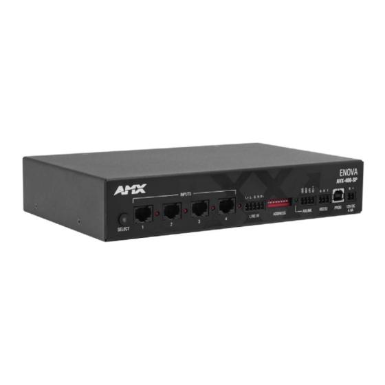
The Enova AVX-400 Twisted Pair Presentation Switcher (FG1350-01) is a four input, multi-format active presentation switcher with auxiliary line level audio input. The AVX-400 (FIG. 1) is a twisted pair switcher with basic projector/ display control via RS-232, but with external control of the switcher via RS-232 or AxLink. This presentation switcher incorporates the following: ... -
Page 10: Specifications
AVX-400 to be controlled from a Master. A green AxLink LED indicates the state of the AxLink port. Note: The AVX-400 cannot be powered by this port or use the port to power other devices. RS-232 Control Port 1 3.5mm Phoenix (3-pin) connector that provides data to external control... - Page 11 (FG1402-52-KW/KB/KA) • UPX-CN+A-EU Component Universal Transmitter Wallplate (EU) (FG1402-52-EW/EB/EA) • AC-SMB Surface Mounting Bracket (FG525) • CC-HD15 Male to HD-15 Male cable (FG10-2170-01) • CC-HD15 Male to 3 RCA3 Male cable (FG10-2170-03) AVX-400 Enova Twisted Pair Presentation Switcher Operation/Reference Guide...
- Page 12 Enova AVX-400 Twisted Pair Presentation Switcher AVX-400 Enova Twisted Pair Presentation Switcher Operation/Reference Guide...
-
Page 13: Wiring And Device Connections
Source Select button The AVX-400 includes one source select button you can press repeatedly to select one of the four input sources. When you press the SELECT button, the first input source is selected. Pressing it again selects the next valid input, and so on. - Page 14 Do not use nanoskew cable, as the cable can cause audio data bleeding into the video. AMX has evaluated several types of category cable for use with UPX wall plates. Of the cable types tested, CAT-5e offers optimal performance for UPX analog signal routing and AMX recommends Belden part number 1583a for best performance.
-
Page 15: Line In
FIG. 9 provides details for wiring from an audio input to a non-5 terminal audio source or destination, such as an RCA connector. Positive and ground wires connect to the source or destination connector. AVX-400 source device FIG. 9 Non 5-terminal audio source and destination wiring AVX-400 Enova Twisted Pair Presentation Switcher Operation/Reference Guide... -
Page 16: Axlink
AxLink Port All AVX-400 units have an AxLink port and adjacent status LED (FIG. 10). This port allows the unit to be controlled from any AxLink Master such as a NetLinx NI Controller. A green LED shows AxLink data activity. When the AxLink port is operating normally, blink patterns include: ... -
Page 17: Device Dip Switches
FIG. 14 RS-232 wiring When using a Novara SP-08-AX 8-Button keypad, connect the AVX-400 to the RS232 output port on the keypad. Consult the documentation for the Novara SP-08-AX 8-Button keypad for more information on the location of the RS232 port on the unit. The following table lists the default button commands for the Novara SP-08-AX 8-Button... -
Page 18: Configuration Port (Prog)
The incoming PWR and GND cable from the power supply must be connected to the corresponding locations within the power connector. The current draw for the AVX-400 with no input plates is 750mA. The following table lists the current draw for each type of input wallplate you can connect to the AVX-400. -
Page 19: Preparing Captive Wires
FIG. 18 demonstrates how to install a suppression ferrite. 1. Release the latch to open 2. Insert the power cable 3. Installation complete. the plastic enclosure. and close the enclosure. FIG. 18 Installing the Suppression Ferrite AVX-400 Enova Twisted Pair Presentation Switcher Operation/Reference Guide... -
Page 20: Rear Panel Components
Wiring and Device Connections Rear Panel Components The following sections describe the options on the rear panel of the AVX-400. DISPLAY CONTROL FIG. 19 DISPLAY CONTROL connector The DISPLAY CONTROL connector is used for controlling a display device such as a projector or large screen LCD. -
Page 21: Speaker
If you connect the port to a wall input plate, use an RJ-45 cable to connect the port on the rear of the wall input plate to one of the source input ports on the front of the switcher. AVX-400 Enova Twisted Pair Presentation Switcher Operation/Reference Guide... -
Page 22: Hd-15 Output Connectors
HD-15 Output connectors Each AVX-400 has two HD-15 output connectors. The outputs enable you to use an HD-15 to COMPONENT or HD-15 to RGB/VGA cable to send video to a display device such as a projector or large screen monitor. The output device displays video from source input devices routing through the AVX-400. -
Page 23: Mounting The Presentation Switcher
Mounting the Presentation Switcher The AVX-400 can be mounted onto a flat surface or mounted under a table. Attach the mounting brackets from the optional mount kit (FG525) to the sides of the switcher as shown in FIG. 26 to mount the unit to any flat surface. FIG. 26 displays the mounting brackets set to attach to the underside of a table. - Page 24 Wiring and Device Connections AVX-400 Enova Twisted Pair Presentation Switcher Operation/Reference Guide...
-
Page 25: Configuration
Clicking on a highlighted port on the device image changes the active input. (This does not work if you are working in Priority mode unless there are no active inputs on the AVX-400.) The active source input is indicated by the illuminated red LED beside the source input. -
Page 26: Supported Operating Systems
Configuration Supported Operating Systems The AMX DCS application is compatible with the following operating systems: • Windows XP Service Pack 3 • Windows 7 Home Premium (32-bit) (US English) • Windows 7 Home Premium (32-bit) Professional (US English) (Russian) • Windows XP Service Pack 3 •... -
Page 27: Display Tab
These options are not available unless you select Priority Switching as the Switching Mode. See the Priority Switching section on page 20 for more information. AVX-400 Enova Twisted Pair Presentation Switcher Operation/Reference Guide... -
Page 28: Enabling Display Control
Device Library Manager section on page 21 for information on adding your specific device to the device library. Perform these steps to enable display control: Click the Display tab on the AMX DCS window. Click the Enabled check box to enable display control. -
Page 29: Setting The Inactive Display Power Down
You can use the DCS software to set an amount of time for a display to be inactive before it shuts down to save power. There must be no active inputs on the AVX-400 for the display power down to occur. This feature is not available for HDMI input sources. - Page 30 Allows you to import Novara or Solecis legacy library files (one-by-one) and add their device definitions to the library. You can also import a previously exported .xml library file. Click to open a web browser which navigates to www.amx.com so you can download a device library file.
-
Page 31: Adding A Device To The Device Library
Add a new AVX executable command for the current device. You can add up to 16 AVX-only commands to a device. Each command specific to the AVX-400 appears in green in the Commands column. AVX-only commands always begin with "AVX_". If you remove this prefix from the command name, AMX DCS will no longer view the command as AVX-only. -
Page 32: Modifying Devices In The Device Library
DCS maintains a separate clipboard from the Windows clipboard. Thus, using Windows shortcuts to cut, copy, and paste may not work as expected. Use the Cut, Copy Data, and Paste buttons in AMX DCS when editing in the Device Library. Importing a Device Library From the File menu, select Device Manager Library. -
Page 33: Renaming A Device
Click Copy Hex to copy the hexadecimal text to the clipboard. Click Close to return to the Device Library Window. Select a command, and click Paste to insert the data into the command/status table. AVX-400 Enova Twisted Pair Presentation Switcher Operation/Reference Guide... -
Page 34: Test Command Tool
The following options appear in this window: Test Command Tool Options Available COM Port(s) The available ports on the connected device. Click the Show COM ports and Connected AMX Devices button to refresh the list of available ports. Show COM Ports and Click to refresh the list of available COM ports. -
Page 35: Updating Firmware
AMX DCS software provides a simple interface for updating your AVX-400 with the latest available version of firmware. You must use a .bin file to upgrade the firmware through AMX DCS software. The latest firmware files can be found at the Tech Center at www.amx.com. - Page 36 Click Close to close the window and return to the AMX DCS window. Remove all HDMI inputs from the AVX-400 if you are going to downgrade your firmware to a previous version. You will be unable to select or change inputs from the select button on the AVX or from DCS until you remove the HDMI input.
-
Page 37: Programming
Programming Programming AxLink Channels Each AxLink device contains 255 channels numbered 1-255. The AxLink channels for the AVX-400 are defined in the table below. AxLink Channels Channel Description Amplifier volume up when the channel is on. Amplifier volume down when the channel is on. -
Page 38: Axlink Commands
One possible output is DST-<ERROR>. You may receive this response for one of the following reasons: • The AVX-400 does not have any display information programmed in it from the DCS application (DCS library). • The AVX-400 cannot communicate with the display after several attempts. -
Page 39: Gct
Queries the power status of the display; returns the current power status. Syntax: SEND_COMMAND "'?PWR'" Sample Output: "Power = On" "Power = Off" "Power = Warming" "Power = Cooling" If the system’s power cannot be determined: "Power = Unknown" AVX-400 Enova Twisted Pair Presentation Switcher Operation/Reference Guide... -
Page 40: Rxoff
Enables sending incoming received characters to the Master. This command is automatically sent by the Master when a 'CREATE_BUFFER' program instruction is executed. The end device does not transmit characters to the Master unless this command is activated on the device. The AVX-400 must be in passthru mode to execute this command. -
Page 41: Axlink Strings
Programming AxLink Strings The following table lists the AxLink strings for the AVX-400: AxLink Strings SEND_STRING Sends a command or query to the display device. The AVX-400 must be in passthru mode to execute this command. Syntax: SEND_STRING <DEV>,"’<text>'" Variable:... -
Page 42: Bgn
Syntax: BUM,$0D Triggers a dynamic user command. AMX advises you to place the AVX in passthru mode prior to executing a dynamic user command. Putting the AVX in passthru mode disables interrogation, and thereby eliminates the possibility of the polling commands interfering with the dynamic commands you send. Because of this, the AVX does not filter the responses back from the device, and extra data may be delivered to you. -
Page 43: Dst
E = temperature: (0=unknown) One possible output is DST-<ERROR>. You may receive this response for one of the following reasons: • The AVX-400 does not have any display information programmed in it from the DCS application (DCS library). • The AVX-400 cannot communicate with the display after several attempts. -
Page 44: Inp
= 1 or 2 stop bits. Example: PBD115200,N,8,1 Sets the display port's baud rate to 115200 baud, no parity, 8 data bits, 1 stop bit. Note: The AVX-400 does not send a response to this command. Returns from passthru mode; re-enables interrogation. Syntax: PDI,$0D Puts the AVX-400 into passthru mode;... -
Page 45: Pss
Sets the red gain level for a source input. This command also applies to the Composite Video Gain on a composite UPX wallplate when you have one connected to the AVX-400. Note: This command cannot be implemented on HDMI Passthru wallplates. -
Page 46: Ton
Note: The number you enter for the EQ setting should correspond to a percentage between 0 and 100. For example, an EQ setting of 60 corresponds to a percentage of 50. Example: VEQ4=30,$0D Sets the EQ level on source input 4 to 30, or 25%. AVX-400 Enova Twisted Pair Presentation Switcher Operation/Reference Guide... -
Page 47: Veq
= the amp volume level setting between -100 and 24dB Example: VLA=20,$0D Sets the balance out volume level to 20dB. VLA+ Increase amp volume by 0.5dB. When the amplifier volume reaches its maximum level, the AVX-400 responds with "MAX". Syntax: VLA+,$0D VLA- Decrease amp volume by 0.5dB. -
Page 48: Vlb
= the balance out volume level setting between -100 and 24dB Example: VLB=11,$0D Sets the balance out volume level to 11dB. VLB+ Increase balance out volume by 0.5dB. When the balance out volume reaches its maximum level, the AVX-400 responds with "MAX". Syntax: VLB+,$0D VLB- Decrease balance out volume by 0.5dB. - Page 49 Programming AVX-400 Enova Twisted Pair Presentation Switcher Operation/Reference Guide...
- Page 50 - Schedules and registration for any AMX University course - Travel and hotel information - Your individual certification requirements and progress 3000 RESEARCH DRIVE, RICHARDSON, TX 75082 USA • 800.222.0193 • 469.624.8000 • 469-624-7153 fax • 800.932.6993 technical support • www.amx.com...
Need help?
Do you have a question about the AVX-400 and is the answer not in the manual?
Questions and answers