
Related Manuals for Phoenix Model CLASSIC-EP


Summary of Contents for Phoenix Model CLASSIC-EP
-
Page 1: Instruction Manual
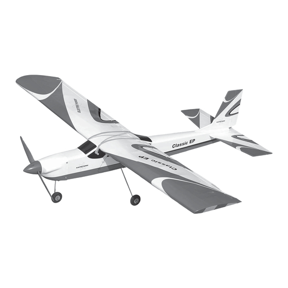
Instruction Manual CLASSIC - EP Wingspan : 1420mm (55.9 inch) Length : 1070mm (42.1 inch) Weight : 1700gr - 2000gr Engine : AXI motor 2826 Radio : 4 channel / 3 servos standard... -
Page 2: Kit Contents
KIT CONTENTS: We have organized the parts as they come out of the box for better identification during assembly. We recommend that you regroup the parts in the same manner. This will ensure you have all of parts required before you begin assembly KIT CONTENTS elevator control system engine mount... - Page 3 Installing the wing halves. Installing the wing halves. Center line Draw a center line. Remove the covering. Glue the wing joiner to the wing. Apply the epoxy into the wing section. Glue the wing by epoxy. Apply the trim tape to the center section on the top and the bottom of the wing where they join.
- Page 4 Servo box Hard wood Remove the covering. Glue the servo box by C.A glue. Install and secure the aileron servo. Install the two nylon control horn. Install the clevis to the aileron pushrod. Insert the silicon tube into the clevis. Clevis Control horn Insert the clevis into the control horn.
- Page 5 Nylon clasp Attach the nylon clasp to the aileron servo arm. Make the same way for the second aileron pushrod. Installing the horizontal and vertical stabilizer. Make a center line onto the horizontal. Remove the covering from the fuselage. Attach the horizontal to the fuselage and check it. Mark the shape of the fuselage onto the top of the horizontal.
- Page 6 Check the horizontal before it dry and remove the wing Glue the horizontal and fuselage by epoxy. out of the fuselage. Glue the horizontal and fuselage by epoxy. Cut away the covering from the fuselage. Mark the shape of the fuselage onto the both side of the Remove the covering from the vertical.
-
Page 7: Installing The Elevator Pushrod
a1 = a2 Check the fin before it dry and remove the wing out of the fuselage. Installing the elevator pushrod. Installing the elevator pushrod. The elevator and rudder linkages. Secure the control horn onto the elevator. Cut away the screw. Remove the covering from the slot. -
Page 8: Installing The Rudder Pushrod
Insert the elevator pushrod into the fuselage. Attach the clevis to the control horn. Install the elevator servo. Cut away the elevator pushrod. Bend "L" the elevator pushrod. Attach the nylon clasp to the servo arm. Installing the rudder pushrod. Installing the rudder pushrod. - Page 9 Remove the covering from the slot. Insert the rudder purshrod into the fuselage. Attach the clevsis to the control horn. Install the rudder servo. Install the metal connector to the servo arm. Install the servor arm into the rudder servo. Cut away the rudder pushrod.
- Page 10 Attach the nylon clasp to the servo arm. Installing the landing gear and nose gear. Installing the landing gear and nose gear. Collar Gear The landing gear and nose gear. Install the collar. Collar Install the wheel. Cut away the covering from the fuselage. Install the landing gear.
- Page 11 Install the nose gear. Secure the nose gear. Attach the nose gear rod into the metal connector and secure it. Installing the engine and cowling. Installing the engine and cowling. Install the engine mount into the fuselage. Glue the engine mount into the fuselage. Glue the three hard wood by epoxy glue.
- Page 12 Install the cowl. Install the propller. I nstalling the receiver and batter. I nstalling the receiver and batter. Install the battery and receiver. Close the window. Rudder servo Receiver Elevator servo Installing the wing dowel . Installing the wing dowel . Wing dowel.
- Page 13 Install two dowels into the fuselage and glue it by C.A glue. Remove the covering. Glue the two plate of wood onto the wing. Install the wing into the fuselage using 6 rubber band.
-
Page 14: Control Throws
CONTROL THROWS BALANCING 1. We highly recommend setting up a plane using the 1. It is critical that your airplane be balanced correctly. control throws listed. Improper balance will cause your plane to lose control and crash. 2. The control throws should be measured at the widest THE CENTER OF GRAVITY IS LOCATED 75 - 80mm point of each control surface.
Need help?
Do you have a question about the CLASSIC-EP and is the answer not in the manual?
Questions and answers