Table of Contents
Advertisement
Quick Links
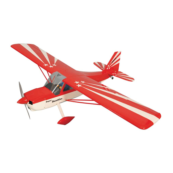
decathlon - EP
The Decathlon - EP is a semi-scale model aircraft for electric motor. Displaying smooth
and stable flight characteristics, The Decathlon - EP offers electric power's convenience
together with exciting, semi-scale looks. Most parts are cut by LASER machine. Quality
wood construction - covered with ORACOVER . Factory painted cowl - 95% almost
ready to fly. Most hardware included and all replacement parts are available.
g
Instruction Manual
Wingspan : 1300mm (51.2 in)
Length
: 980mm (38.6 in)
Weight
: 1600g - 1800g
Engine
: AXI motor 2814 or 2820
Radio
: 4 channel / 3 servo
Advertisement
Table of Contents

Related Manuals for Phoenix Model decathlon - EP


Summary of Contents for Phoenix Model decathlon - EP
-
Page 1: Instruction Manual
Instruction Manual decathlon - EP The Decathlon - EP is a semi-scale model aircraft for electric motor. Displaying smooth and stable flight characteristics, The Decathlon - EP offers electric power's convenience together with exciting, semi-scale looks. Most parts are cut by LASER machine. Quality wood construction - covered with ORACOVER . -
Page 2: Kit Contents
KIT CONTENTS: We have organized the parts as they come out of the box for better identification during assembly. We recommend that you regroup the parts in the same manner. This will ensure you have all of parts required before you begin assembly KIT CONTENTS AIR FRAME ASSEMBLIES RUDDER CONTROL SYSTEM... -
Page 3: Tools And Supplies Needed
TOOLS AND SUPPLIES NEEDED PREPARATIONS Remove the tape and separate the ailerons • Medium C/A glue from the wing and the elevators from the stab. • 30 minute epoxy Use a covering iron with a covering sock on • 6 minute epoxy high heat to tighten the covering if necessary. -
Page 4: Installing The Aileron Servos
INSTALLING THE AILERON SERVOS 1. Install the rubber grommets and brass eyelets onto the aileron servo. 2. Using a modeling knife, remove the covering from over the pre-cut servo arm exit hole on the Servo lead aileron servo tray / hatch. This hole will allow the servo arm to pass through when installing the aileron pushrods. -
Page 5: Installing The Aileron Linkages
1. Attach the pushrod to the outer hole in the control horn and slide it through the metal connector. 2. Locate one nylon servo arm, and using wire cutters, remove all but one of the arms. Using a 2mm drill bit, enlarge the third hole out from the center of the arm to accommodate the aileron pushrod wire. -
Page 6: Horizontal Stabilizer Installation
HORIZONTAL STABILIZER INSTALLATION 1. Using a modeling knife, cut away the covering from the fuselage for the stabilizer and remove it. 5. Remove the stabilizer. Using the lines you just drew as a guide, carefully remove the covering from between them using a modeling knife. When cutting through the covering to remove it, cut with only enough pressure to only cut through the covering it's self. -
Page 7: Vertical Stabilizer Installation
8. Repeat step # 1 - # 2 from installing the ailerons to install the elevator. Remove the covering Glue with epoxy 4. Slide the vertical stabilizer back in place. Using a triangle, check to ensure that the vertical stabilizer is aligned 90 degree to the horizontal stabilizer. -
Page 8: Tail Wheel Installation
3. Using a modeling knife, carefully cut out two line from the margin of the hole onto the wheel pant. Glue with epoxy Just cut only one side of the wheel pant, where the main gear will install. Be sure to make a left and right wheel pant. -
Page 9: Installing The Elevator Linkages
SERVO INSTALLATION INSTALLING THE ELEVATOR linkages INSTALLING THE FUSELAGE SERVOS Repeat step # 1 - # 4 from installing the aileron linkages to install the elevator linkages. 1. Install the rubber grommets and brass collets into the elevator, rudder and throttle servos. Test fit the servos into the servo tray. - Page 10 Metal pushrod INSTALLING THE ENGINE and cowling 1. Prepare the engine mount and glue it. 2. Glue the engine mount into the fuselage.
-
Page 11: Installing The Antenna
INSTALLING THE battery and receiver 3. Install the motor and secure it. Install the battery and receiver. Receiver Battery 4. The cowling. Open and close the canopy Screw 5. Secure the cowling. INSTALLING THE antenna Glue with epoxy 6. Install the propeller. Remove the covering... -
Page 12: Installing The Wing Strut
4. If the nose of the plane falls, the plane is heavy INSTALLING THE WING STRUT nose. To correct this first move the battery pack 1. Screw the wing strut into the fuselage. further back in the fuselage. If this is not possible or does not correct it, stick small amounts of lead weight on the fuselage under the horizontal stabilizer. -
Page 13: Flight Preparation Pre Flight Check
FLIGHT PREPARATION PRE FLIGHT CHECK 1. Completely charge your transmitter and receiver batteries before your first day of flying. 2. Check every bolt and every glue joint in your plane to ensure that everything is tight and well bonded. 3. Double check the balance of the airplane 4. -
Page 14: Metric Conversions
I/C FLIGHT WARNINGS Metric Conversions Inches x 25.4 = mm (conversion factor) 1/64" .4 mm 3/16" 4.8 mm 1" 25.4 mm 21" = 533.4 mm 1/32" .8 mm 1/4" 6.4 mm 2" = 50.8 mm 24" = 609.6 mm 1/16" 1.6 mm 3/8"... - Page 15 I/C FLIGHT GUIDELINES Operate the control sticks on the When ready to fly, first extend the transmitter and check that the control transmitter aerial. surfaces move freely and in the ALWAYS land the model INTO the CORRECT directions. wind, this ensures that the model lands at the slowest possible speed.
Need help?
Do you have a question about the decathlon - EP and is the answer not in the manual?
Questions and answers