
Related Manuals for Phoenix Model Classic


Summary of Contents for Phoenix Model Classic
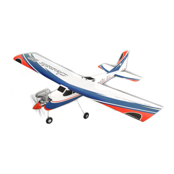
- Page 1 Instruction Manual SIZE 61-75 Wingspan : 1723mm (67.83 inches) Length : 1400mm (55.12 inches) Weight : 3300g - 3500g Radio : 4 Channel - 5 standard servo Engine : 61 - 75 two stroke / 72 - 91 four stroke...
-
Page 3: Kit Contents
CLASSIC Instruction Manual KIT CONTENTS: We have organized the parts as they come out of the box for better identification during assembly. We recommend that you regroup the parts in the same manner. This will ensure you have all of parts required before you begin assembly... -
Page 4: Safety Precaution
This will assure proper assembly. The TEMPORARY PIN CLASSIC is hand made from natural materials, every TO KEEP HINGE plane is unique and minor adjustments may have to CENTERED be made. -
Page 5: Installing The Aileron Servos
CLASSIC Instruction Manual INSTALLING THE AILERON SERVOS 5. Place the aileron servo tray / hatch into the servo box on the bottom of the wing and drill 1. Install the rubber grommets and brass eyelets 1,6mm pilot holes through the tray and the onto the aileron servo. -
Page 6: Installing The Aileron Linkages
CLASSIC Instruction Manual RIGHT WRONG Silicone Tube 3. Repeat step # 1 - # 2 to install the control horn on the opposite aileron. INSTALLING THE AILERON LINKAGES 9. Repeat step # 4 - # 8 to install the second 1. -
Page 7: Installing The Vertical Stabilizer
CLASSIC Instruction Manual 3. Secure the wing to the fuselage using the INSTALLING the VERTICAL STABILIZER plastic screws 1. Using a modeling knife, remove the covering on the top of the fuselage for the vertical stabilizer. Screw Remove the covering INSTALLING the HORIZONTAL STABILIZER 1. -
Page 8: Installing The Landing Gear
CLASSIC Instruction Manual 4. Slide the vertical stabilizer back in place. Using a triangle, check to ensure that the vertical stabilizer is aligned 90 degree to the horizontal stabilizer. 5. When you are sure that everything is a aligned Main gear correctly, mix up a generous amount of 30 minute epoxy. -
Page 9: Installing The Stopper Assembly
CLASSIC Instruction Manual FIGURE #4 STREERING SCREW Z-BEND PUSHROD WIRE 6. Locate the nose gear wire. Slide the nose gear wire up through the lower portion of the nose gear block, then through the nylon steering arm, then through the upper portion of the nose FUEL TANK installation gear block. -
Page 10: Installing The Elevator Pushrod
CLASSIC Instruction Manual 6. When satisfied with the alignment of the stopper 2. Mount the servos to the tray using the mounting assembly tighten the 3mm x 20mm machine screws provided with your radio system. screw until the rubber stopper expands and seals the tank opening. -
Page 11: Installing The Rudder Pushrod
CLASSIC Instruction Manual 12. With the elevator halves and elevator servo centered, carefully place a mark on the elevator pushrod wire where it crosses the hole in the servo arm. 13. Using pliers, carefully make a 90 degree bend up at the mark made. Cut off the excess wire, leaving about 8mm beyond the bend. -
Page 12: Installing The Throttle
CLASSIC Instruction Manual INSTALLING THE THROTTLE 1. Install one adjustable metal connector through the third hole out from the center of one servo arm, enlarge the hole in the servo arm using a 2mm drill bit to accommodate the servo connector. -
Page 13: Installing The Receiver And Battery
CLASSIC Instruction Manual BALANCING 1. It is critical that your airplane be balanced correctly. Improper balance will cause your plane to lose control and crash. THE CENTER OF GRAVITY IS LOCATED 85mm BACK FROM THE LEADING EDGE OF THE WING, AT THE FUSELAGE. -
Page 14: Control Throws
CLASSIC Instruction Manual CONTROL THROWS 1. We highly recommend setting up a plane using the control throws listed. 2. The control throws should be measured at the widest point of each control surface. 3. Check to be sure the control surfaces move in the correct directions. - Page 15 Instruction Manual CLASSIC I/C FLIGHT WARNINGS Always operate in open areas, away Keep all onlookers (especially small from factories, hospitals, schools, THE PROPELLER IS DANGEROUS children and animals) well back from buildings and houses etc. NEVER fly Keep fingers, clothing (ties, shirt the area of operation.
- Page 16 CLASSIC Instruction Manual I/C FLIGHT GUIDELINES Operate the control sticks on the When ready to fly, first extend the transmitter and check that the control transmitter aerial. surfaces move freely and in the ALWAYS land the model INTO the CORRECT directions.
Need help?
Do you have a question about the Classic and is the answer not in the manual?
Questions and answers