Phoenix Model Corsair F4U Instruction Manual
Hide thumbs
Also See for Corsair F4U:
- Instruction manual (17 pages) ,
- Instruction manual (17 pages) ,
- Instruction manual (52 pages)
Table of Contents

Related Manuals for Phoenix Model Corsair F4U


Summary of Contents for Phoenix Model Corsair F4U
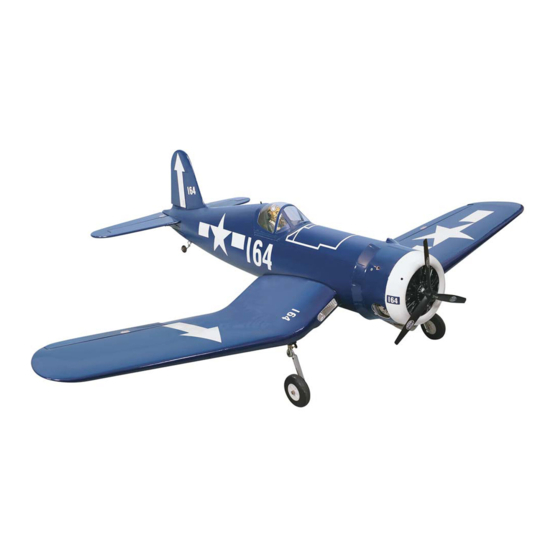
- Page 1 I n s t r u c t i o n M a n u a l CORSAIR F4U Wingspan : 1485mm (58.46 inches) Length : 1160mm (45.67 inches) Weight : 2800gr - 3000gr Engine : 46-55/ 2 stroke_52-70/ 4 stroke...
-
Page 3: Kit Contents
Instruction Manual CORSAIR F4U KIT CONTENTS: We have organized the parts as they come out of the box for better identification during assembly. We recommend that you regroup the parts in the same manner. This will ensure you have all of parts required before you begin assembly. -
Page 4: Tools And Supplies Needed
This will assure proper 1. Test fit the ailerons to the wing with the hinges. assembly. The Corsair F4U is hand made from If the hinges don’t remain centered, stick a pin natural materials, every plane is unique and through the middle of the hinge to hold it in minor adjustments may have to be made. -
Page 5: Installing The Control Horns
Instruction Manual CORSAIR F4U INSTALL THE AILERONS SERVOS & PUSHRODS 1. Install the servo in the wing require the use of one 305mm servo extension for each aileron servo. One Y-harness connector is required and is used to allow the aileron servo to plug into one slot in your receiver. -
Page 6: Installing The Aileron Linkages
Instruction Manual CORSAIR F4U RIGHT WRONG 2. Drill through the mark you made with a (1.6mm) drill bit. Hard the hole with thin CA. Install the control horn. Remember use thread locking compound to secure. 2. Locate one nylon servo arm, and using wire Note: The hole on the nylon horn is aligned cutters, remove all but one of the arms. -
Page 7: Installing The Landing Gear
Instruction Manual CORSAIR F4U 7. Insert the 90 degree bend down through the hole in the servo arm. Install one nylon snap keeper over the wire to secure it to the arm. epoxy glue Install the servo arm retaining screw and remove the masking tape from the aileron. - Page 8 Instruction Manual CORSAIR F4U 2. One set of the landing gear. 7. Insert the retract landing gear into the block and 3. Turn the wing up side down and using a mark four holes onto the block. Take out the...
- Page 9 Instruction Manual CORSAIR F4U 10. Install the metal connector into the landing gear. 27mm 12. Install two metal connector to the servo arm of the gear servo. 11. Make the same way for the second retract landing gear Open position...
-
Page 10: Installing The Horizontal Stabilizer
Instruction Manual CORSAIR F4U Close position 13. Secure the wing to the fuselage using the 2. Draw a center line onto the horizontal stabilizer and slide it into the fuselage. plastic screws. 3. Check the fit of the horizontal stabilizer in its slot. -
Page 11: Installing The Rudder
Instruction Manual CORSAIR F4U 5. Remove the stabilizer. Using the lines you just drew as a guide, carefully remove the covering from between them using a modeling knife. When cutting through the covering to remove it, cut with only enough pressure to only cut through the covering it's self. -
Page 12: Installing The Tail Wheel
Instruction Manual CORSAIR F4U 2. Remove the covering. 2. Install the collar into the tail gear. 3. Glue the hinges using C.A glue. 3. Remove the covering and open the screw from the left of the rudder. 4. Slide the tail gear to the fuselage through the rudder and secure it. -
Page 13: Installing The Engine
Instruction Manual CORSAIR F4U FUEL TANK INSTALLING THE STOPPER ASSEMBLY 1. The stopper has been pre-assembled at the factory. 2. Using a modeling knife, cut one length of silicon fuel line (the length of silicon fuel line is calculated by how the weighted clunk should rest about 8mm away from the rear of the tank and move freely inside the tank). -
Page 14: Installing The Elevator Pushrod
Instruction Manual CORSAIR F4U Blow through one of the lines to ensure the fuel Working from inside the fuselage, slide the lines have not become kinked inside the fuel threaded end of the pushrod until it reaches the tank compartment. Air should flow through exit slot. -
Page 15: Installing The Rudder Pushrod
Instruction Manual CORSAIR F4U 12. With the elevator halves and elevator servo centered, carefully place a mark on the elevator pushrod wire where it crosses the hole in the servo arm. 13. Using pliers, carefully make a 90 degree bend up at the mark made. -
Page 16: Mounting The Cowl
Instruction Manual CORSAIR F4U 2. Plug the throttle servo into the receiver and turn Slide the cowl back over the engine and on the radio system. Check to ensure that the secure it in place using four 3mm x 12mm throttle servo output shaft is moving in the wood screws. -
Page 17: Installing The Switch
Instruction Manual CORSAIR F4U FINAL ASSEMBLY INSTALLING THE SPINNER Install the spinner back-plate, propeller and spinner cone. The spinner cone is held in place using two 3mm x 20mm wood screws. The propeller should not touch any part of the spinner cone. -
Page 18: Lateral Balance
Instruction Manual CORSAIR F4U LATERAL BALANCE LOW RATE After you have balanced a plane on the C.G. Ailerons : 12mm up 12mm down You should laterally balance it. Doing this will Elevator : 10mm up 10mm down help the airplane track straighter. - Page 19 Instruction Manual CORSAIR F4U I/C FLIGHT WARNINGS Always operate in open areas, away Keep all onlookers (especially small from factories, hospitals, schools, THE PROPELLER IS DANGEROUS children and animals) well back from buildings and houses etc. NEVER fly Keep fingers, clothing (ties, shirt the area of operation.
- Page 20 Instruction Manual CORSAIR F4U I/C FLIGHT GUIDELINES Operate the control sticks on the When ready to fly, first extend the transmitter and check that the control transmitter aerial. surfaces move freely and in the ALWAYS land the model INTO the CORRECT directions.
Need help?
Do you have a question about the Corsair F4U and is the answer not in the manual?
Questions and answers