
Related Manuals for Phoenix Model trainer 60


Summary of Contents for Phoenix Model trainer 60
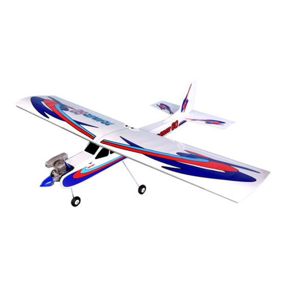
- Page 1 I n s t r u c t i o n M a n u a l Wingspan : 1900 mm (74.8 inches) Length 1450 mm (57 inches) Weight 3360 gr Engine 60 two strokes Radio : 4 channels / 5 servos standard...
-
Page 2: Kit Contents
Instruction Manual Trainer 60 KIT CONTENTS: We have organized the parts as they come out of the box for better identification during assembly. We recommend that you regroup the parts in the same manner. This will ensure you have all of parts required before you begin assembly. -
Page 3: Installing The Aileron Servos
This will assure proper assembly. The TRAINER 60 ARF is hand made from natural materials, every plane is unique and minor adjustments may have to be made. -
Page 4: Installing The Control Horns
Instruction Manual Trainer 60 5. Place the aileron servo tray / hatch into the servo box on the bottom of the wing and drill 1,6mm pilot holes through the tray and the servo box for each of the four mounting screws. -
Page 5: Wing Assembly
Instruction Manual Trainer 60 2. Attach the clevis to the outer hole in the control horn. Install a silicone tube on the clevis. 3. Locate one nylon servo arm, and using wire cutters, remove all but one of the arms. Using a... - Page 6 Instruction Manual Trainer 60 Cover wing joint with self adhesive trim strip. Tape Trim the covering from the stab where it will glue onto the fuselage. Cut only through the covering, do not cut into the balsa. HORIZONTAL-VERTICAL INSTALLATION Remove the covering...
-
Page 7: Main Gear Installation
Instruction Manual Trainer 60 Nose gear Glue epoxy Wire pushrod Steering arm MAIN GEAR INSTALLATION Cut the covering from the slot in the landing gear Install nose wheel using supplied wheel collars. mount. Put landing gear wires in fuselage bottom and secure using screws and nylon straps. -
Page 8: Engine Installation
Instruction Manual Trainer 60 ENGINE INSTALLATION Rudder servo Insert the Z-bend of the throttle pushrod into the throttle arm of the engine. See the "high throttle" photo on page 9 Install the engine of your choice using the Philip head screws. Make sure the engine is pointing straight ahead or pointing a little to the right, i. -
Page 9: Throttle Linkage
Instruction Manual Trainer 60 Elevator servo Control horn Screw Rudder servo Install the elevator pushrod in fuselage. Thread a nylon clevis at least 6 mm onto the pushrod. Route it to the elevator, attach clevis to horn and secure using small piece of silicone tubing. - Page 10 Instruction Manual Trainer 60 SETTING UP THE THROTTLE This is a very important stage in the completion of the model. The throttle must open and close fully - without the linkage binding at either end of its travel. Work by setting the "mid throttle" position first, followed by the low and high.
-
Page 11: Control Throws
We wish you many enjoyable flights with your plane and once again thank you for your 2. The control throws should be measured at the choosing a Phoenix Model's product. widest point of each surface!. Ailerons : 10mm up 10mm down... -
Page 12: Metric Conversions
I/C FLIGHT WARNINGS Always operate in open areas, away Keep all onlookers (especially small THE PROPELLER IS DANGEROUS from factories, hospitals, schools, children and animals) well back from buildings and houses etc. NEVER fly Keep fingers, clothing (ties, shirt the area of operation. This is a flying your aircraft close to people or built sleeves, scarves) or any other loose aircraft, which will cause serious...
Need help?
Do you have a question about the trainer 60 and is the answer not in the manual?
Questions and answers