
Related Manuals for Phoenix Model Cap 232


Summary of Contents for Phoenix Model Cap 232
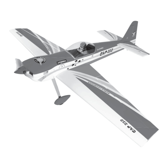
- Page 1 I n s t r u c t i o n M a n u a l Wingspan: 620mm (63.8 inch) Length: 430mm (56.3 inch) Weight: 3500g - 4000g Engine: - 75 two stroke Radio: 4 channel / 5 high torque servo standard servo...
-
Page 2: Kit Contents
Instruction Manual CAP 232 KIT CONTENTS: We have organized the parts as they come out of the box for better identification during assembly. We recommend that you regroup the parts in the same manner. This will ensure you have all of parts required before you begin assembly. -
Page 3: Tools And Supplies Needed
1. Please trial fit all the parts. Make sure you have the correct parts and that they fit and are aligned properly before gluing! This will assure proper assembly. The Cap 232/ 61 is hand made from INSTALL THE AILERONS SERVOS & PUSHRODS natural materials, every plane is unique and 1. -
Page 4: Installing The Control Horns
Instruction Manual CAP 232 4. Attach the servo extension to the aileron servo. Secure the connectors together using a large piece of heat shrink tubing, tape or other method for securing the connectors together. 5. Turn the wing panel right side up. Using a modeling knife, remove the covering from over the precut servo box. -
Page 5: Installing The Aileron Linkages
Instruction Manual CAP 232 M3 nut IN LINE M3 clevis WING TIP 2. Drill through the mark you made with a (3mm) 2. Make the same way for the plastic linkball to the drill bit. Hard the hole with thin CA. Install the other side of the pushrod wire. -
Page 6: Joining The Wing Halves
Instruction Manual CAP 232 5. When satisfied with the fit of the wing halves, remove the wing halves and the dihedral brace. JOINING THE WING HALVES 1. Mix a generous amount of 30 minute epoxy. Working with only one wing half for now, apply a thin layer of epoxy inside the carton tube and to only half of the dihedral brace. -
Page 7: Installing The Horizontal Stabilizer
Instruction Manual CAP 232 5. Remove the stabilizer. Using the lines you just drew as a guide, carefully remove the covering INSTALLING THE HORIZONTAL STABILIZER from between them using a modeling knife. 1. Using a modeling knife, cut away the covering When cutting through the covering to remove it, from the fuselage for the stabilizer and remove it. -
Page 8: Installing The Vertical Stabilizer
Instruction Manual CAP 232 8. When you are sure that everything is aligned correctly, mix up a generous amount of 30 minute epoxy. Apply a thin layer to the bottom of the stabilizer mounting area and to the stabilizer mounting platform sides in the fuselage. -
Page 9: Installing The Tail Wheel
Instruction Manual CAP 232 INSTALLING THE MAIN LANDING GEAR INSTALLING THE TAIL WHEEL 1. Nuts have been installed at the factory. 1. Using the knife cut away the wood from the bottom of the rudder and slide the two nylon 2. -
Page 10: Installing The Engine
Instruction Manual CAP 232 After installing the wheel pant, apply a small drop of thin C/A to the bottom nut. 9. Repeat step # 1-8 to install the second wheel pant assembly. INSTALLING THE THROTTLE PUSHROD HOUSING 1. Install the engine mount to the fuselage. -
Page 11: Installing The Stopper Assembly
Instruction Manual CAP 232 5. Test fit the stopper assembly into the tank. It may be necessary to remove some of the flashing around the tank opening using a modeling knife. If flashing is present, make sure none of it falls into the tank. -
Page 12: Installing The Elevator Servo
Instruction Manual CAP 232 Engine side INSTALLING THE ELEVATOR SERVO INSTALLING THE ELEVATOR LINKAGES 1. Remove the covering from both size of the fuselage. The elevator linkages are assembled as shown below 2. Install two servo to the fuselage as shown. -
Page 13: Installing The Rudder Linkages
Instruction Manual CAP 232 INSTALLING THE RUDDER LINKAGES Repeat these step as installing the aileron linkages (Page 4 and page 5). 22mm 22mm 165mm INSTALLING THE RUDDER SERVO Remove the covering from the exit slot for rudder. MOUNTING THE COWL Install the rudder servo to the fuselage as shown. -
Page 14: Final Assembly
Instruction Manual CAP 232 INSTALLING THE RECEIVER AND BATTERY 1. Plug the servo leads and the switch lead into the receiver. You may want to plug an aileron extension into the receiver to make plugging in the aileron servo lead easier when you are installing the wing. -
Page 15: Lateral Balance
Instruction Manual CAP 232 3-D PERFORMANCE SETTINGS 110mm The CAP 232/ 61 will perform 3-D aerobatics easily if you use the largest engines recommended within the engine range. If you setup your airplane to do 3D maneuvers, you will need to be throttle conscious; that is, never apply full throttle on straight and level flying or in dives to prevent flutter. - Page 16 I/C FLIGHT WARNINGS Always operate in open areas, away Keep all onlookers (especially small from factories, hospitals, schools, THE PROPELLER IS DANGEROUS children and animals) well back from buildings and houses etc. NEVER fly Keep fingers, clothing (ties, shirt the area of operation. This is a flying your aircraft close to people or built sleeves, scarves) or any other loose aircraft, which will cause serious...
- Page 17 I/C FLIGHT GUIDELINES Operate the control sticks on the When ready to fly, first extend the transmitter and check that the control transmitter aerial. surfaces move freely and in the ALWAYS land the model INTO the CORRECT directions. wind, this ensures that the model lands at the slowest possible speed.
Need help?
Do you have a question about the Cap 232 and is the answer not in the manual?
Questions and answers