Intermec EasyCoder PC41 Service Manual
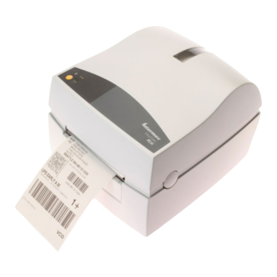
Bar code label
printer
Hide thumbs
Also See for EasyCoder PC41:
- Developer's manual (116 pages) ,
- Installation instructions manual (16 pages) ,
- User manual (68 pages)
Table of Contents
Advertisement
Quick Links
Advertisement
Table of Contents

Related Manuals for Intermec EasyCoder PC41


Summary of Contents for Intermec EasyCoder PC41
- Page 1 Service Manual EasyCoder PC41 Bar Code Label Printer...
- Page 2 The information contained herein is proprietary and is provided solely for the purpose of allowing customers to operate and/or service Intermec manufactured equipment and is not to be released, reproduced, or used for any other purpose without written permission of Intermec.
-
Page 3: Table Of Contents
About This Manual ....................... v Notices and Approvals ......................vi Models and Options 1.1 Models..........................2 1.2 Options ...........................3 1.3 EasyCoder PC41 Specifications ..................4 1.4 EasyCoder PC41 Measures .....................6 Main Parts 2.1 Taking the Printer Apart ....................10 2.2 Reassembling the Printer ....................10 2.3 Exploded View ......................11... - Page 4 9.2 Memory Sizes ........................65 9.3 Schematics ........................66 Starting Up 10.1 Overview 10.2 Normal Mode ......................70 10.3 Factory Default Mode ....................70 10.4 Test Mode ........................70 10.5 Dump Mode .......................71 Firmware Upgrading 73 11.1 Requirements ......................74 Troubleshooting 12.1 Checklist........................76 Intermec EasyCoder PC41—Service Manual...
-
Page 5: About This Manual
About This Manual This Service Manual is intended to facilitate installation, troubleshooting and repair of the Intermec EasyCoder PC41 in the version delivered at the date of publishing. The on-going product improvement can be followed in the Technical Bulletins published at the Intermec Knowledge Center. -
Page 6: Notices And Approvals
EU Standard EN 55022 (The European Union) WARNING This is a Class A ITE product. In a domestic environment this product may cause radio interference in which case the user may be required to take adequate measures. Intermec EasyCoder PC41—Service Manual... -
Page 7: Models And Options
Models and Options This chapter provides information on the various models of the EasyCoder PC41 and contains specifications and physical measures. Intermec EasyCoder PC41—Service Manual... -
Page 8: Models
The machine label, which provides information on model, part number, serial number, etc. is attached to the bottom of the base frame. The EasyCoder PC41 has a separate power supply unit that delivers 24 VDC to the printer's main board, where it is transformed to the various voltages required by the printhead, motor, and logics (see Chapter 8.1). -
Page 9: Options
The available options for the EasyCoder PC41 are serial and parallel inter- face cables, a memory cartridge, a paper cutter, a battery unit and an assort- ment of power cords. Refer to the EasyCoder PC41 Spare Parts Catalog or Spare Parts List for updated information. -
Page 10: Easycoder Pc41 Specifications
Chapter 1—Models and Options 1.3 EasyCoder PC41 Specifications Printing Print Technique Thermal Transfer or Direct Thermal Printhead Resolution 203.2 dpi (8 dots/mm) Print Speed (selectable) 50, 75 or 100 mm/sec. (2, 3 or 4 in/sec.) Print Width (max) at 203.2 dpi 104 mm (4.1 inches) - Page 11 1 × Centronics Parallel Accessories and Options Parallel Interface Cable Standard RS-232 Cable Option Memory Cartridge Option 1MB flash Paper Cutter Option V-spring for stiff/thick media Option Mobile Battery Unit Option Battery Pack Option Battery Charger Option Intermec EasyCoder PC41—Service Manual...
-
Page 12: Easycoder Pc41 Measures
Chapter 1—Models and Options 1.4 EasyCoder PC41 Measures Side View 259 mm (10.20 in) 333 mm (13.11 in) Intermec EasyCoder PC41—Service Manual... -
Page 13: Front View
Chapter 1—Models and Options Front View 50 mm (1.97 in) 133 mm (5.24 in) Rear View Intermec EasyCoder PC41—Service Manual... -
Page 14: Top View
Chapter 1—Models and Options Top View Bottom View 39 mm (1.54 in) 184 mm (7.24 in) 17 mm (0.67 in) 154 mm (6.06 in) Intermec EasyCoder PC41—Service Manual... -
Page 15: Main Parts
Main Parts This chapter shows the printer’s main parts and explains how the printer is taken apart and reassembled. Each of the main parts is described in more detail in the chapters that follow. Intermec EasyCoder PC41—Service Manual... -
Page 16: Taking The Printer Apart
Chapter 2—Main Parts 2.1 Taking the Printer Apart The EasyCoder PC41 is a so called double clam-shell design, where the print frame and the top cover are hinged to a base frame. The bottom part of the base frame is enclosed by the bottom cover, which is held by four Phillips screws. -
Page 17: Exploded View
Chapter 2—Main Parts 2.3 Exploded View Top Cover Print Frame E-ring Bolts Base Frame E-ring Bottom Cover Intermec EasyCoder PC41—Service Manual... - Page 18 Chapter 2—Main Parts Intermec EasyCoder PC41—Service Manual...
-
Page 19: Top Cover
Top Cover This chapter describes the parts of the top cover and explains how to replace the tear-off plate. Intermec EasyCoder PC41—Service Manual... -
Page 20: Description
Note that in case of a PC41 DT printer, the locks are cut off and you will need to insert a flat screwdriver or similar to release the locks. Top cover locks Base locks Intermec EasyCoder PC41—Service Manual... -
Page 21: Tear-Off Plate
Two L-shaped rails hold the plate. If you need to remove the tear-off plate with- out discarding it, be careful not to break the tabs, which are quite delicate. Intermec EasyCoder PC41—Service Manual... - Page 22 Chapter 3—Top Cover Intermec EasyCoder PC41—Service Manual...
-
Page 23: Print Frame
This chapter describes the print frame which contains the thermal print- head, the transfer ribbon supply, the LED control lamp, the Feed key, and the emitter of the label gap sensor. It also provides instructions for how to replace the various parts. Intermec EasyCoder PC41—Service Manual... -
Page 24: Description
Thermal Transfer (TTR) Model Short top cover locks LED control lamp Label gap sensor (Emitter) Feed switch Ribbon load label Print frame moulding Printhead Ribbon end sensor Transfer ribbon mechanism Long top cover locks Intermec EasyCoder PC41—Service Manual... -
Page 25: Led And Feed Switch
Phillips screw and a snap lock. The Feed Switch PCB is inserted between two rails in the moulding and is cov- ered by an isolation sheet. Screw Cable cover Snap lock Isolation sheet Feed switch PCB Print frame Intermec EasyCoder PC41—Service Manual... - Page 26 Chapter 4—Print Frame Schematics LED1 LED1 YELLOW Intermec EasyCoder PC41—Service Manual...
-
Page 27: Top Cover Locks
Feed Switch PCB earlier in this chap- ter. The right-side spring hook is easily accessible in the DT model whereas in the TTR model, you will need to dismantle the ribbon takeup mechanism (see Chapter 4.8). Intermec EasyCoder PC41—Service Manual... -
Page 28: Printhead
Some simple measures can be taken by the user to prevent premature wear- out: • Clean the printhead regularly, as described in the EasyCoder PC41 User’s Guide. Not only will a dirty printhead result in an inferior printout, but any residue on the dots will prevent heat to dissipate through the ribbon and media. - Page 29 • Continue to press forward so the U-shaped slots in the sides of the print- head bracket also become disengaged from the studs at the inner sides of the cavity in the print frame. V-Spring Pocket Stud Printhead assy Slot Intermec EasyCoder PC41—Service Manual...
- Page 30 V-spring runs between the two guiding ridges on the printhead bracket. • Test that the printhead can move slightly up against the pressure force of the V-spring. Finally, check that the printhead is working properly by printing a test label as described in Chapter 10. Intermec EasyCoder PC41—Service Manual...
-
Page 31: Ribbon End Sensor
• Install a replacement sensor in reverse order. Ribbon end sensor Intermec EasyCoder PC41—Service Manual... - Page 32 Chapter 4—Print Frame Schematics ON: ENABLE STRIPPER OFF: DISABLE RIBBON 100K Intermec EasyCoder PC41—Service Manual...
-
Page 33: Label Gap Sensor (Emitter)
• Remove the screw that holds the circuit board and pull it straight up while carefully manipulating the cable and connector through the hinge and out through the wall of the ribbon supply cavity. • Install a replacement circuit board in reverse order. Label gap sensor Schematics Intermec EasyCoder PC41—Service Manual... -
Page 34: Ribbon Feed Mechanism
Ribbon supply shaft Spring StarLoc washer Ribbon return cap Spring Friction plate Wool fiber disc Fixed holder Screws (2) Intermec EasyCoder PC41—Service Manual... - Page 35 The shaft is held by an E-ring inside the Feed button cavity. A spring on the shaft makes it possible to snap the core in place. No adjustments are facilitated. E-ring Washer Spring Ribbon core holder Intermec EasyCoder PC41—Service Manual...
- Page 36 E-ring and lift out the entire rewind assembly without dismantling it any further. This way, you will keep the factory adjustments. Ribbon rewind shaft One-way clutch holder Wool fiber disc Gear Friction plate Spring Screws (2) Fixed holder E-ring Intermec EasyCoder PC41—Service Manual...
- Page 37 There are no facilities for adjustments. Bolt Spring Gears (2) E-rings (2) Intermec EasyCoder PC41—Service Manual...
- Page 38 Chapter 4—Print Frame Intermec EasyCoder PC41—Service Manual...
-
Page 39: Base Frame
Base Frame This chapter describes the main parts of the base frame and provides replacement instructions. Intermec EasyCoder PC41—Service Manual... -
Page 40: Main Parts
The base frame consists of a plastic moulding to which a number of assem- blies are fitted. The same base frame is used for both the DT and the TTR models of the EasyCoder PC41. The optional paper cutter is normally factory-fitted, but could be field-... -
Page 41: Main Board
• Disconnect all cables to the main board. • Remove the nut at the top of the rear plate and disconnect the ground- ing cable • Install a new board in reverse order. Refer to Chapter 7.3 for a connec- tion diagram. Intermec EasyCoder PC41—Service Manual... -
Page 42: Platen Roller
D-shaped hole, and that the tab on the right-side bushing fits into the corresponding slot in the base frame moulding before locking the assem- bly with the platen cover. Plastic bushing with brass insert Platen cover Platen roller Snap-lock Right-side bushing Gear Intermec EasyCoder PC41—Service Manual... -
Page 43: Peel-Off Mechanism
• Disengage the hinges from the inner walls of the base frame moulding and pull out the peel-off mechanism. • Install a replacement unit in reverse order. Label Taken Sensor Roller To J10 on main board Hinges Intermec EasyCoder PC41—Service Manual... - Page 44 Chapter 5—Base Frame ON/OFF Switch The operator can enable/disable the label taken sensor by manipulating the switch on the inside of the peel-off mechanism, as shown below. Schematics ON: ENABLE STRIPPER OFF: DISABLE RIBBON 100K Intermec EasyCoder PC41—Service Manual...
-
Page 45: Motor Assy
• Pull out the motor and bracket. • Install a replacement unit in reverse order. Pulley Motor, thermistor, and bracket M3 nut To J4 on main board Gear Washer To J2 on main board E-ring E-ring M3 nut Gear Intermec EasyCoder PC41—Service Manual... -
Page 46: Media Guides
5.6 Media Guides Description The EasyCoder PC41 is designed to have the media centered in relation to the printhead. It has two stoppers that keep the media roll centered on the media spindle and two guides that align the media before it is fed under the printhead. -
Page 47: Base Locks
• Remove the screws that hold the locks. • Install new base locks in reverse order. In the illustration below, the right-side base lock is exploded to better show the principles of design. Base frame Screw Push button Holder Spring Screws (2) Intermec EasyCoder PC41—Service Manual... - Page 48 Chapter 5—Base Frame Intermec EasyCoder PC41—Service Manual...
-
Page 49: Label Gap/Black Mark Sensors
• Disconnect the cables from J3 and J7 on the main board. • Adjust media guides for maximum media width. • Remove the screws that hold the sensor board. • Install new board in reverse order. Intermec EasyCoder PC41—Service Manual... - Page 50 Chapter 5—Base Frame Schematics Intermec EasyCoder PC41—Service Manual...
-
Page 51: Media Spindle
As an alternative to using a media supply roll on the spindle, fan-folds or similar can be routed from an external supply behind the printer and into the media cavity through a slot in above the printer's rear plate. 1 inch 25.4 mm 1.5 inch 38.1 mm Intermec EasyCoder PC41—Service Manual... - Page 52 Chapter 5—Base Frame Intermec EasyCoder PC41—Service Manual...
-
Page 53: Bottom Cover
Bottom Cover This chapter describes the bottom cover and explains how to remove the accessory cover. Intermec EasyCoder PC41—Service Manual... -
Page 54: Bottom Cover
Four rubber feet are glued to the bottom plate, which also has four screw pockets that allow the printer to be permanently attached to a table or similar. Screw pockets Bottom cover Accessory cover Rubber foot (4) Screw (4) Intermec EasyCoder PC41—Service Manual... -
Page 55: Main Board
Main Board This chapter describes the main board including test points, connections, memory organization, and schematics. Intermec EasyCoder PC41—Service Manual... -
Page 56: Description
The main board has a memory where the user can store graphics and forms. The memory can be expanded by fitting an optional memory cartridge directly to a connector on the main board. PRODUCT/REV. Intermec EasyCoder PC41—Service Manual... -
Page 57: Accessing The Main Board
J10 LTS J1 Cutter J9 Printhead J4 Thermistor J15 Centronics J7 Lower Label Gap Sensor/Black Mark Sensor J3 Upper Label Gap Sensor J5 Ribbon End Sensor Printhead GND J6 Feed Switch/LED J13 RS 232 J12 Memory Cartridge Intermec EasyCoder PC41—Service Manual... -
Page 58: Test Points
Chapter 7—Main Board 7.4 Test Points PP124 PP107 PP73 PP115 PP75 PP162 PP235 PP62 PP11 PP13 PP164 PP48 PP117 PP221 PP216 PP226 PP228 PP201 PP179 PP191 PP176 Main Board, test points on reverse side Intermec EasyCoder PC41—Service Manual... - Page 59 System clock (20MHz frequency) J11 pin 5 RESET* System reset J16 pin 1 Logic supply voltage J16 pin 6 Ground J16 pin 1 J16 pin 6 J11 pin 5 Main Board, test points on upper side Intermec EasyCoder PC41—Service Manual...
-
Page 60: Block Diagram
LEDs , FEED; J6 DRAM Print Head U3, U4 J8, J9 (2M) (512 K) IEEE 1284; J15 M68332 RS-232; J13 FLASH Memory System Bus Expansion BDM Debug Power Supply A/D Converter Motor Drivers DC 24V, 5V U24, U25 Intermec EasyCoder PC41—Service Manual... -
Page 61: Internal Memory
Chapter 7—Main Board 7.6 Internal Memory The EasyCoder PC41 has, as a standard, a DRAM memory of 512K and an EPROM memory of 2048K fitted on the main board. The internal memory can be expanded using an optional memory car- tridge, see Chapter 9. -
Page 62: Schematics
SAMSUNG KM416V256D DSACK1* .1U/25V STBCHP PP97 0603 STBDUR PP109 PP158 47ohm U17B PP93 0603 150P/50V PP144 0603 PP205 ROMCSL* STROBE* A[23..0] PP132 PP125 74HC08 PP138 PP116 PP117 DRAMLCS* .1U/25V PP196 DRAMHCS* 0603 PP203 PP217 CPU & Memory Intermec EasyCoder PC41—Service Manual... - Page 63 DTR* T2OUT T2IN T3OUT T3IN PIN11 T4OUT T4IN R1IN R1OUT CTS* R2IN R2OUT AUX* R3IN R3OUT PP35 R4IN R4OUT PP33 PP20 PP21 220ohm CTS* PP191 150P/50V 150P/50V 150P/50V 0603 0603 0603 SERIAL PORT Serial Port (RS-232) Intermec EasyCoder PC41—Service Manual...
- Page 64 Chapter 7—Main Board Miscellaneous Intermec EasyCoder PC41—Service Manual...
- Page 65 Chapter 7—Main Board Miscellaneous (cont.) Intermec EasyCoder PC41—Service Manual...
- Page 66 Chapter 7—Main Board Intermec EasyCoder PC41—Service Manual...
-
Page 67: Power Supply
Power Supply This chapter describes the separate power supply. Intermec EasyCoder PC41—Service Manual... -
Page 68: Description
Chapter 8—Power Supply 8.1 Description The EasyCoder PC41 has a separate power supply. The power supply is designed for an input of 100 to 240 VAC, 50 to 60 Hz, 1.9A, 100 to 200 VA and gives an output voltage of 24 VDC, 3.0A. -
Page 69: Memory Cartridge (Option)
Memory Cartridge (option) This chapter describes the optional memory cartridge that can be used to expand the printer’s built-in memory. Intermec EasyCoder PC41—Service Manual... -
Page 70: Description
The switch on the short side of the memory cartridge controls a feature used exclusively in the EasyCoder PC4 printer. Since this feature in incom- patible with the PC41, the position of the switch is of no significance. Intermec EasyCoder PC41—Service Manual... -
Page 71: Memory Sizes
Chapter 9—Memory Cartridge 9.2 Memory Sizes The memory cartridge provides the printer with an additional 1024 Kb of Flash memory that can be used to store forms, graphics and fonts. Intermec EasyCoder PC41—Service Manual... -
Page 72: Schematics
Chapter 9—Memory Cartridge 9.3 Schematics RAM1 RAM1 RAM2 RAM2 RAM1 RAM1 RAM2 RAM2 Memory Cartridge Intermec EasyCoder PC41—Service Manual... -
Page 73: Starting Up
Starting Up This chapter describes how the printer starts up in normal mode or test mode and how the printer automatically switches from test mode to dump mode. Intermec EasyCoder PC41—Service Manual... -
Page 74: Overview
If this is the case, the printer will proceed into Test mode. If not, the printer will go into Factory Default Mode. If the Feed key is not pressed, the printer will start operating in Normal mode. Intermec EasyCoder PC41—Service Manual... - Page 75 Green LED on Dump Mode Is data Is Feed key received on Pressed? any port ? Suspend Print Data Dump Mode Print SW config labels Is Feed key Wait for reboot Pressed? Print Pitch Label Intermec EasyCoder PC41—Service Manual...
-
Page 76: Normal Mode
In this final stage of the Test mode, the user may print a Pitch label by pressing the feed key. Leaving this state however requires a reboot. Intermec EasyCoder PC41—Service Manual... -
Page 77: Dump Mode
ASCII number (between ASCII 000 dec and ASCII 255 dec). To leave the Dump Mode, briefly tap the Feed key without entering any characters. This will cause the printer to proceed with its test sequence. Intermec EasyCoder PC41—Service Manual... - Page 78 Chapter 10—Starting Up Intermec EasyCoder PC41—Service Manual...
-
Page 79: Firmware Upgrading
Firmware Upgrading This chapter explains how to upgrade the printer with a later firmware version. Intermec EasyCoder PC41—Service Manual... -
Page 80: Requirements
Locate the EPROM slots (see below) and remove the old EPROMs using a PLCC Extractor tool or equivalent. Insert the new EPROMs into their appropriate slots (U3 and U4 respec- tively), and put the accessory cover back in place. Intermec EasyCoder PC41—Service Manual... -
Page 81: Troubleshooting
Troubleshooting This chapter list some possible error conditions and suggests remedies depending on the cause of the error. Intermec EasyCoder PC41—Service Manual... -
Page 82: Checklist
- Check that the heat-sensitive side faces the printhead. • Ribbon faults (TTR): - Verify that the printer is loaded with transfer ribbon and that the ink- coated sided faces the receiving face material. Intermec EasyCoder PC41—Service Manual... - Page 83 - Enter the Test Mode as described in Chapter 10.4 and check the soft- ware configuration label to see that LABEL STOCK is set correctly. • Label gap sensor out of order. - Check both emitter and receiver boards for visible damage and bad connections. Replace if necessary. Intermec EasyCoder PC41—Service Manual...
- Page 84 Possible Cause of Problem and Suggested Measures: • Media jam in the cutter (option). - Clear the jammed media. If necessary, remove the cutter housing and rotate the screw on the side of the cutter motor casing. Intermec EasyCoder PC41—Service Manual...
- Page 85 • Ribbon end sensor out of order. - Check for foreign objects that can block the light beam and for bad connections. Replace if necessary. Intermec EasyCoder PC41—Service Manual...
- Page 86 Chapter 12—Troubleshooting Intermec EasyCoder PC41—Service Manual...
- Page 88 Intermec Technologies Corporation Corporate Headquarters 6001 36th Avenue West Everett , WA 98203 U.S.A. tel +425.348.2600 fax +425.355.9551 www.intermec.com EasyCoder PC41 Service Manual *1-960645-00* *1-960645-00*...
Need help?
Do you have a question about the EasyCoder PC41 and is the answer not in the manual?
Questions and answers