Table of Contents
Advertisement
Original Instruction Manual
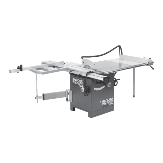
TS315
Cast Iron Table
Saw with Scoring
IMPORTANT
For your safety read instructions
carefully before assembling or using
this product. Save this manual for
future reference.
Version 2.1
February 2010
Woodworking Machines & Accessories
Record Power Ltd
Telephone: 01246 561 520
Unit B, Adelphi Way
Fax: 01246 561 537
Staveley S43 3LS
HEALTH AND SAFETY GUIDELINES
Always follow the instructions provided with the manual. Always wear safety glasses when using woodworking
equipment. Always disconnect the power before adjusting any equipment. Failure to observe proper safety
procedures and guidelines can result in serious injury.
WARNING: Do not allow familiarity (gained from frequent use of your machine and accessories) to become
commonplace. Always remember that a careless fraction of a second is sufficient to inflict severe injury.
Email: sales@recordpower.co.uk
www.recordpower.co.uk
Always wear safety glasses when
using woodworking equipment.
Always read the instructions
provided before using
woodworking equipment.
Advertisement
Table of Contents

Related Manuals for Record Power TS315


Summary of Contents for Record Power TS315
- Page 1 Save this manual for future reference. Version 2.1 February 2010 Woodworking Machines & Accessories Record Power Ltd Telephone: 01246 561 520 Email: sales@recordpower.co.uk Unit B, Adelphi Way Fax: 01246 561 537 www.recordpower.co.uk Staveley S43 3LS HEALTH AND SAFETY GUIDELINES Always follow the instructions provided with the manual.
-
Page 2: Table Of Contents
Contents Page Health & Safety Guidance Record Power Guarantee Additional Safety Instructions for Table Saws 1 General Information Foreword Machine Description Machine identification Getting to know your machine Technical specification Recommended protective clothing Noise emission Prescribed use of the machine... -
Page 3: Health & Safety Guidance
Health & Safety Guidance READ ALL THE INSTRUCTIONS IN THIS MANUAL CAREFULLY BEFORE ASSEMBLY, authorized service facility or qualified electrician. INSTALLATION AND USE OF THIS PRODUCT. • Inspect extension cords (if used) periodically and replace if damaged. Always KEEP THESE INSTRUCTIONS IN A SAFE PLACE FOR FUTURE REFERENCE. use properly rated extension cord. -
Page 4: Record Power Guarantee
2.2.2 We are given a reasonable opportunity after receiving notice of the claim to examine the product. 2.2.3 If asked to do so by us, you return the product to Record Power's premises or other approved premises such as those of the supplying dealer, for the examination to take place. -
Page 5: Additional Safety Instructions For Table Saws
Additional Safety Instructions For Table Saws SAFETY IS A COMBINATION OF OPERATOR Safety Warnings are not removed or painted over. New labels are available COMMON SENSE AND ALERTNESS AT ALL TIMES WHEN THE TABLE from Customer Services. SAW IS BEING USED. 16. -
Page 6: General Information
1. General Information FOREWORD This manual must be read and understood before operating the machine. This will provide a better working knowledge of the machine, for increased safety and to obtain the best results. Machine Description MACHINE IDENTIFICATION There is a metallic identification plate fixed to the machine, containing the manufacturer's data, year of construction, serial number and blade data. -
Page 7: Technical Specification
Technical Specification SPECIFICATION TS315 Main blade size: 254mm With optional table insert and scoring blade removed: 315mm Scoring blade size: 80mm Main blade bore: 30mm Scrolling blade bore: 20mm Blade speed: 4000rpm Max width of cut with fence: 1250mm Sliding carriage stroke:... -
Page 8: Additional Safety Instructions For Table Saw
2.8 Additional Safety Instructions For Table Saws SAFETY IS A COMBINATION OF OPERATOR COMMON SENSE AND ALERTNESS AT ALL TIMES WHEN THE TABLE SAW IS BEING USED. WARNING: FOR YOUR OWN SAFETY, DO NOT ATTEMPT TO OPERATE YOUR TABLE SAW UNTIL IT IS COMPLETELY ASSEMBLED AND INSTALLED ACCORDING TO THE INSTRUCTIONS. -
Page 9: Lifting And Unloading
3. Installation 3.1. Lifting And Unloading CAUTION Some of the lathe components are stored inside the cabinet for ease of shipment. We recommend assistance is sought to take them out. CAUTION Lifting and handling should only be carried out by skilled personnel specially trained to execute this kind of operation. -
Page 10: Identifying Shipping Boxes
3.3 Identifying Shipping Boxes BEFORE ASSEMBLY It is advisable that before unpacking to have plenty of paper towels or cloths available to clean off the rust preservative. Contents of the shipment: 1. Main Table Saw - two cartons (Fig. 3) Fig.3... -
Page 11: Installations Of Loose Parts
3.4. Installation of Loose Parts 3.4.1 Blade Guard - Installation CAUTION The guard must always be used and must be positioned in such a way as to completely cover the blade. • Lift the saw assembly by means of the lever A after loosening handle B. -
Page 12: Squaring Frame Installation
3.4.3 Squaring Frame Installation (Optional) Mount the squaring frame support bracket (A, Fig.10) onto the cabinet. Insert the slider (B, Fig.10) into the swing arm and make sure the thrust bearing is in place (C, Fig 10). Insert the support (D, Fig. 11) in the groove of the sliding beam (E, Fig.11). -
Page 13: Rear Extension Table Installation
3.4.5 Rear Extension Table Installation Installation: Mount the table (A, Fig.14) using the screws (B, Fig.14). Carefully level the table by adjusting the grub screw (C, Fig.14). Fig.14 3.4.6 Right Extension Table Installation NOTICE When installing the extension table with 468x790 dimensions, it is advisable to seek assistance before attempting to install. -
Page 14: Fence Installation
3.4.7 Fence Installation Fit the fence rest (H, Fig.17) to the work table (B, Fig.17) and place the spacers in between. Tighten the nuts (Q, Fig.17) with flat & spring washers inbetween. Manually tighten nuts (S, Fig.17) against the supplementary table (A, Fig.17) and finally tighten nuts (Q, Fig.17). -
Page 15: Electrical Connection
On initial start-up check the direction of rotation, if it is incorrect then invert the two phase wires (for machines with 3 phase supply). Direction of rotation of machines with single-phase supply is pre-determined during production . On completion of the installation check that the terminal box is closed correctly and that the plug points are locked. TS315 Single phase TS315 Three phase... -
Page 16: Installation And Adjustment
4. Installation And Adjustment 4.1. MAIN BLADE INSTALLATION AND ADJUSTMENT CAUTION: Handle the tools with protective gloves. Disconnect input power. Position the saw assembly at 90º and raise it as high as possible. Position the squaring frame (A, Fig.21) as shown in the figure and move the sliding beam (H, Fig.21) completely to the right and loosen the screws (M, Fig.21). -
Page 17: Scoring Blade Installation And Adjustment
4.2 Scoring Blade Installation And Adjustment To assemble the scoring blade: Insert wrench (A, Fig.25) in the blade-holding flange hole. Loosen lock nut (C, Fig.25) using a hex wrench (B, Fig.25) and remove flange (D, Fig.25). Assemble, by following this sequence, these parts: blade (E, Fig.25) with the teeth opposed to the ones of the saw, flange D and nut C. -
Page 18: Saw Blade Tilting And Lifting
4.3. Saw Blade Tilting And Lifting Release knob (E, Fig.29) and adjust handwheel (F, Fig.29) to adjust the saw blade height. Loosen the knob (G, Fig.29) and act on the knob (H, Fig.29) to adjust the tilting of the saw blade. Read the tilting value of the saw blade on the index. - Page 19 Fence Alignment 1 (Fig.32) Align the fence assembly in or out until parallel with the side of the blade by turning the adjustment nuts and the fence bolts accordingly. If the fixing nuts FENCE have been tightened, these will need slackening off before this adjustment can be made.
-
Page 20: Operating Procedures
5. Operating Procedures 5.1. Control Panel The electric board consist of the following devices: 5.1.1 Control Functions A - ON/OFF switch - connects and disconnects input power. O - the machine is not powered; I - the machine is powered. B - Stop button. -
Page 21: Cutting With Rip Fence
3) Third Cut Position the stop (F, Fig.37) according to the cutting width to be executed; Turn the panel 90° Place the trimmed side against the aluminium ruler (E, Fig.37) and against the stop (F, Fig.37) Proceed with cutting. 4) Fourth Cut Repeat the operations as step 3. -
Page 22: Maintenance
6. Maintenance 6.1. V-belt Replacement And Tightening Check the belt tension after the first 10 hours of machine operation. It is recommended that at least every 6 months a periodical check on the belt is carried out. Do not overstretch the belts or you may overload the bearings. Overstretching may overheat and destroy the belts. -
Page 23: General Lubrication
6.1.2 Scoring Belt Completely lower the saw assembly; Push the belt tightener (E, Fig.44) to the left and taking off the belt (F, Fig.44); Taking off the spring (A, Fig.44) from the tightener (E, Fig.44) and replace the belt. Fig.44 6.2. - Page 24 7. Diagrams & Components Ref No. Description Fence Carriage bolt M6X30 T bracket Mitre gauge Screw M6X70 Plastic nut Right end cap Tapping screw ST4.2X9.5 Left end cap Screw M6X50 Washer 6 Washer 6 Washer 4 Screw M4X12 Indicator base Roll pin Indicator Screw M4X8...
- Page 25 Ref No. Description Tapping screw ST3.5X25 Blade guard 1 Guide plate Blade guard 2 Hex. Locknut M5 Plastice nut Hex. Nut M10 Spring washer 10 Flat washer 10 Pressure plate Screw M6X16 Guide bracket Hex. Bolt M8X20 Hex. Bolt M10X25 Pull bracket Collar bracket Tube...
- Page 26 Ref No. Description Set screw M6x12 Hex. Socket screw M8x60 Hex. Bolt M8x12 Locking handle Main table Flat washer 8 Cam locking wheel Table insert 1 Spring washer 8 Fence rail mounting screw Table insert 2 Fence Front rail Screw M6x10 Hex.
- Page 27 Ref No. Description Ref No. Description Flat washer Locknut M24 Spring washer Flat washer Hex. Bolt M10X25 Screw M8X16 Trunnion bracket Lock knob Adjusting knob Asm. Handle bolt Hex. Nut M8 Wheel handle Channel base Hex. Nut M10 Hex. Bolt M8X60 Handwheel Pan head screw M5X12 Set screw M8X8...
- Page 28 Ref No. Description Square fence Scale Square nut Set screw M6X10 Tapping screw ST3.6X9.5 Hex. Socket head screw M6X12 Shaft Fence end cap Roll pin 6x45 Sliding bracket Washer 6 Knob Flip stop Magnifier Extended fence Scale Tube Bracket Extended fence bracket Scale Set screw M5X6 Locate plate...
- Page 29 Ref No. Description Sliding table Square nut Handle Hex. Nut Square nut Washer 8 Lock handle Position screw Position handle Plate Screw M6X12 Support plate, front Support plate, rear Hex. Bolt M10X25 Washer 10 Pressure plate Knob cover Knob body Hex.
- Page 30 EU Declaration Of Conformity Cert No: EU / TS315 / 1 RECORD POWER LIMITED, Unit B, Ireland Industrial Est. Adelphi Way, Staveley, Chesterfield S43 3LS declares that the machinery described:- Type: Table Saw 2. Model No: TS315 Serial No .................
- Page 32 Visit www.recordpower.co.uk for the full range of Record Power products. Woodworking Blades Machinery Craft Accessories Finishes and Waxes DVDs Accessories Woodworking Machines & Accessories Record Power Limited Telephone: 01246 561 520 Email: sales@recordpower.co.uk Unit B, Adelphi Way www.recordpower.co.uk Facsimile: 01246 561 537 Ireland Industrial Est.
Need help?
Do you have a question about the TS315 and is the answer not in the manual?
Questions and answers