Table of Contents
Advertisement
Original Instruction Manual
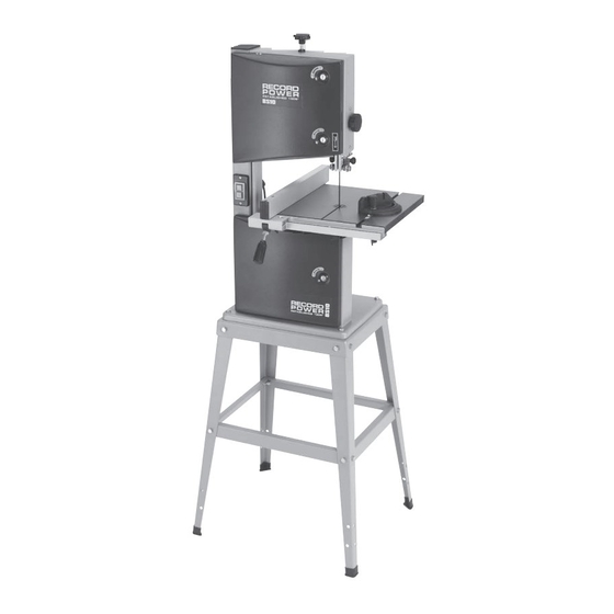
BS10
10" Standard Bandsaw
Version 3.1
February 2014
It is important to register your product as soon as possible in order to receive efficient after sales
support and be entitled to the full 5 year guarantee. Your statutory rights are not affected.
Kg
Always wear safety glasses when
using woodworking equipment.
To register this product please visit
www.recordpower.info
Please see back cover for contact details.
Important
i
For your safety read instructions carefully before
assembling or using this product.
Always read the instructions
provided before using
Save this manual for future reference.
woodworking equipment.
Advertisement
Table of Contents

Subscribe to Our Youtube Channel
Related Manuals for Record Power BS10


Summary of Contents for Record Power BS10
- Page 1 Original Instruction Manual BS10 10" Standard Bandsaw Version 3.1 February 2014 To register this product please visit www.recordpower.info It is important to register your product as soon as possible in order to receive efficient after sales support and be entitled to the full 5 year guarantee. Your statutory rights are not affected.
-
Page 2: Table Of Contents
Contents Explanation of Symbols Health & Safety Guidance Additional Health & Safety Guidance for Bandsaws Record Power Guarantee Getting to Know the Bandsaw Specifications Assembly of the Optional Leg Stand Machine Assembly Machine Setting 10 Bandsaw Blade Set Up 11 Electrical Connection & Wiring Diagram 12 Operation &... -
Page 3: Explanation Of Symbols
1. Explanation of Symbols THE SYMBOLS AND THEIR MEANINGS SHOWN BELOW MAY BE USED THROUGHOUT THIS MANUAL. PLEASE ENSURE THAT YOU TAKE THE APPROPRIATE ACTION WHEREVER THE WARNINGS ARE USED. Mandatory Instructions Read and fully understand the instruction manual before attempting to use the machine. Indicates an instruction that requires particular attention Wear protective eyewear Use respiratory protective equipment... -
Page 4: Health & Safety Guidance
2. General Health & Safety Guidance Ensure that you carefully read and fully understand the • Some machines have optional wheel kits available to allow them instructions in this manual before assembly, installation to be manoeuvred around the workshop as required. Care should and use of this product. - Page 5 2. General Health & Safety Guidance - cont. 11. Consider the work area environment • Extension cables should be routed away from the direct working area • Do not expose the machine to rain or damp conditions. to prevent a trip hazard. 19.
-
Page 6: Additional Health & Safety Guidance For Bandsaws
2. General Health & Safety Guidance - cont. guards in place. 30. Check for damaged parts • Before each use of the machine, it should be carefully checked to 27. Maintain your machine with care determine that it will operate properly and perform its •... -
Page 7: Record Power Guarantee
Product; 1.2.3 if asked to do so by Record Power, its Authorised Distributor This Guarantee does not confer any rights other than those expressly set out above and does not cover any claims for or Authorised Dealer, you return the Product, at your own consequential loss or damage. -
Page 8: Getting To Know The Bandsaw
5. Getting to Know the Bandsaw Item Description Item Description Item Description Blade tensioning knob Rip fence Tracking knob lock Rise & fall knob Rip fence rail Motor rating plate Blade Table Table tilting handle Upper blade guides Optional leg stand 40 mm dust extraction port Mitre fence Tracking knob... -
Page 9: Assembly Of The Optional Leg Stand
7. Assembly of the Optional Leg Stand Tools Required For Assembly & Maintenance 3 mm hex wrench (included with the machine) 5 mm hex wrench (not supplied) 10 - 13 mm combination wrench (included with the machine) CAUTION! The machine is heavy. Additional help or a suitable lifting device or support will be required for lifting the machine onto the stand. - Page 10 7. Assembly of the Optional Leg Stand - Cont. Fig. 7.1 Note: When assembling the legstand do not fully tighten the nuts and bolts until the assembly is complete. Stand Assembly 1. Locate the four legs (D) and secure them to the upper frame (A) using the nuts, bolts and washers supplied.
- Page 11 7. Assembly of the Optional Leg Stand - Cont. 4. Slide the rubber feet (E) onto the bottom of the bandsaw Fig. 7.4 legs (D) and position the frame upright. Once the frame is upright all fixings should be fully tightened, see Fig 7.4.
-
Page 12: Machine Assembly
Components Included and Unpacking The machine is supplied partly assembled. Prior to use, further assembly is required. When unpacking the machine the following components are included for the initial assembly. BS10 Bandsaw Table Fence Fence rail Mitre fence Push stick... - Page 13 8. Machine Assembly - Cont. After removing the machine it is advisable to make an Fig. 8.1 initial setting to the lower blade guides. Open the lower door, using a flat blade screwdriver to undo the door locks and slacken the two blade guide locking knobs (Fig. 8.1, A), then position the guides to within 0.5 mm of the blade.
- Page 14 8. Machine Assembly - Cont. Fitting the Rip Fence Fig. 8.5 1. Slide the rip fence (Fig. 8.5, A) assembly onto the fence rail (Fig. 8.5, B) ensuring that the retaining plate at the end of the rip fence is located under the rear edge of the table.
-
Page 15: Machine Setting
9. Machine Setting Fig. 9.1 CAUTION! Before carrying out any adjustments or maintenance ensure that the machine is isolated and disconnected from the electricity supply. Tilting the Table The tilt mechanism will be used when squaring the table to the blade. Tilt the table as follows: 1. - Page 16 9. Machine Setting - Cont. Fig. 9.4A Fig. 9.4B CAUTION! Before carrying out any adjustments or maintenance ensure that the machine is isolated and disconnected from the electricity supply. Tensioning the Blade The blade tensioning knob should be used to increase or decrease tension (See Fig.
- Page 17 9. Machine Setting - Cont. Tracking the Bandsaw Blade Fig. 9.5 Isolate the machine from the power supply by unplugging the mains plug. Set the tracking of the blade before setting the blade guides. Once the blade is tensioned, track the blade by turning the upper bandwheel by hand and adjusting the tracking knob (Fig.
-
Page 18: Bandsaw Blade Set Up
10. Bandsaw Blade Set Up Fig. 10.1 CAUTION! Before carrying out any adjustments or maintenance ensure that the machine is isolated and disconnected from the electricity supply. Adjusting the Upper Guides To adjust the upper blade guides, position the guide assembly relative to the blade by slackening off the guide carrier locking knob (Fig. -
Page 19: Electrical Connection & Wiring Diagram
11. Electrical Connection & Wiring Diagram Machines supplied for use in the UK are fitted with a 3 pin plug The wire coloured brown must always be connected to the terminal conforming to BS1363, fitted with a fuse conforming to BS1362 and marked ‘L1’. -
Page 20: Operation & Bandsawing Practice
Remove the faulty For special applications, custom blades can be supplied please call component and replace only with genuine Record Power replacement Customer Services in your country and we can advise you accordingly on parts. - Page 21 12. Operation & Bandsawing Practice - Cont Blade Selection (TPI) - Cont. Material Material Thickness <6 mm 6-12 mm 12-25 mm >25mm Having selected an appropriate blade for the particular thickness and type Perspex 16 TPI 14 TPI of material to be sawn, it is essential that the saw blade is allowed to cut freely by not applying too much pressure.
- Page 22 Bandsaw Blades Narrow Blade Wide Blade Note: As well as the blades listed, we can also supply bandsaw blades to almost any specification please call Record Power Customer Services in your country. Application Application Application...
- Page 23 12. Operation & Bandsawing Practice - Cont Ex. 2. Always support round pieces with a wedge or vee block. Take extreme Ex. 5. Jig for accurate repetitive wedges. care as there is a danger that if the work is not secured properly the blade will snatch the work piece, potentially causing it to spin or bounce back at you.
-
Page 24: Dust Extraction
Record Power Extractors can be used simultaneously giving maximum suction but in this Record Power offer a range of high quality dust extractors, we offer mode the extractor must be switched off for 20 minutes every hour. both drum and bag type extractors which filter down 0.5 micron 0.5 micron filtration... - Page 25 13. Dust Extraction - Cont DX1000 RSDE1 RSDE2 RSDE/2A DX4000 DX5000 CX2000 CX2600 CX3000 Bandsaws Circular saws Sanders Intermittent usage Recommended Recommended Recommended Recommended Recommended Recommended Bandsaws Circular saws Sanders Heavy usage Recommended Recommended Planer Thicknessers Spindle Moulders Universals Intermittent usage Recommended Recommended Can be used...
-
Page 26: Maintenance
14. Maintenance Replacing the Bandsaw Blade Fig. 14.1 CAUTION! Before carrying out any adjustments or maintenance ensure that the machine is isolated and disconnected from the electricity supply. HAZARD! Take great care when unpacking the bandsaw blade as they are usually folded and can spring out very suddenly with great force. - Page 27 14. Maintenance - Cont. 7. Check the blade tracking on the newly fitted blade by turning the upper wheel by hand. To track the blade loosen the locking knob on the back of the machine and turn the tracking knob clockwise to move the blade back and anti clockwise to move the blade forward.
- Page 28 14. Maintenance - Cont. The Blade Guide System Fig. 14.5 In general usage it is advisable to carefully apply silicone spray to the blade guides to ensure free movement of the rollers, do not use oil or grease for lubrication as this will attract dust and cause the rollers to jam.
- Page 29 14. Maintenance - Cont. The Bandwheel Bearings Fig. 14.8 The bandwheel bearings are sealed for life units which will need replacing periodically depending on usage. To replace the bearings; first ensure that there is no blade fitted. Now remove the circlip from the hub and remove the bandwheel, you will notice that there are two separate bearings fitted in the hub pressed up against each other.
-
Page 30: Parts List & Diagrams
15. Parts List & Diagrams Part Number Part Name Quantity Part Number Part Name Quantity 31503031 Slotted Insert Door Lock GB96-85 6 Washer 31503022 Washer DJ315B03025 Guide wheel 31503032 Housing DJ315B03027 31503020 Washer DJ315B03025 Roller DJ250B04001 Lower Door DJ315B03023 Shaft 31503033 Housing with Nut GB/T276-94 625-2Z... - Page 31 15. Parts List & Diagrams - Cont. Part Number Part Name Quantity GB5783-86 M6 x 16 Hex Head Bolt GB6171-86 M14 x 1.5 Hex Nut GB93-87 14 Spring Washer DJ250A04006 Bearing Bolt lower GB93-87 6 Spring Washer DJ25005003-1 Motor Mounting Plate YYL7114 Motor DJ250A05006...
- Page 32 15. Parts list and Diagrams - Cont.
- Page 33 15. Parts list and Diagrams - Cont.
-
Page 34: Eu Declaration Of Conformity
EU Declaration of Conformity Cert No: EU / BS10 / 1 Record Power Limited, Centenary House, 11 Midland Way, Barlborough Links, Chesterfield, Derbyshire S43 4XA declares that the machinery described:- 1. Type: Bandsaw Model No: BS10 3. Serial No ................. - Page 36 Woodworking Machinery & Accessories United Kingdom Eire Australia New Zealand Record Power Ltd Record Power Ltd Tools 4 Industry Tools 4 Industry Centenary House, 11 Midland Way Centenary House, 11 Midland Way Po Box 3844 Po Box 276079 Barlborough Links, Chesterfield...
Need help?
Do you have a question about the BS10 and is the answer not in the manual?
Questions and answers