
Related Manuals for Record Power TS250RS


Summary of Contents for Record Power TS250RS
-
Page 1: Table Saw
Instruction Manual Table Saw TS250RS IMPORTANT For your safety read instructions carefully before assembling or using this product. Save this manual for future reference. -
Page 2: Table Of Contents
INDEX GENERAL INFORMATION FOREWORD MACHINE IDENTIFICATION CUSTOMER SERVICE RECOMMENDATIONS SAFETY PRECAUTIONS SAFETY REGULATIONS RESIDUAL RISKS SAFETY AND INFORMATION SIGNALS SPECIFICATIONS MAIN COMPONENTS TECHNICAL SPECIFICATION ELECTRICAL CONNECTION NOISE LEVEL DUST EXTRACTION SAFETY DEVICES INSTALLATION CONTENTS OF PACKAGE INSTALLATION ZONE CHARACTERISTICS INSTALL OF LOOSE PARTS - INTRODUCTION ADJUSTMENT 5.1 SLIDING TABLE FLATNESS ADJUSTMENT 5.2 EXTENSION TABLE FLATNESS ADJUSTMENT... -
Page 3: General Information
1. GENERAL INFORMATION FOREWORD Some information and illustrations in this manual may difer from the machine in your possession, since all the configurations inherent in the machine complete with all the optionals are described and illustrated. Therefore, refer only to that information strictly connected with the machine configuration you have purchased. -
Page 4: Safety Precautions
2. SAFETY PRECAUTIONS SAFETY REGULATIONS Read carefully the operation and maintenance manual before starting, using, servicing and WARNING carrying out any other operation on the machine. The manufacturer disclaims all responsibilities for damages to persons or things, which might be caused by any failure to comply with the safety regulations. -
Page 5: Residual Risks
RESIDUAL RISKS Despite observance of all the safety regulations, and use according to the rules described in this manual, residual risks may still be present, among which the most recurring are: - contact with tool - contact with moving parts (belts, pulleys, etc..) - recoil of the piece or part of it - accidents due to wood splinters or fragments - tool insert ejection... -
Page 6: Specifications
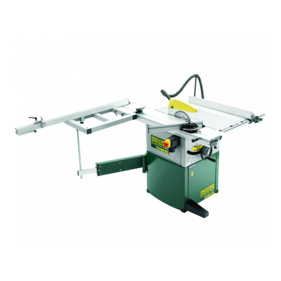
6 - Sliding table 14 - Tilting handwheel 7 - Telescopic fence 15 - Rip fence assembly 8 - Square sliding table 16 - Core unit TECHNICAL SPECIFICATION TS250RS SPECIFICATION 230V/50HZ 380V/50HZ Motor Voltage 2HP, S6 40% 2.5HP, S6 40%... -
Page 7: Electrical Connection
3.3 ELECTRICAL CONNECTION - Electrical installation should be carried out by competent, qualified personnel. - The mains connection should be made using the terminal box. - Replacement of the power supply cable should only be done by a qualified electrician. WARNING To avoid electrocution or fire, any maintenance or repair to electrical system should be done only by qualified... -
Page 8: Safety Devices
Ensure that the suction system guarantees these values at the hood-houth connection point. (Fig.3.5) Suction mouth diameter: A - Blade guard ..ø30 mm B - Body dust suction ..ø100 mm Connect the mouths to the suction system with flexible tubes of adequate diameter. -
Page 9: Contents Of Package
4. INSTALLATION CAUTION Assembly need to be done by an experienced and trained person. 4.1 CONTENTS OF PACKAGE - The machine is supplied partly assembled. Prior to use, further assembly is required. - When unpacking the machine the following components are included for the initial assembly. - If any parts are missing, do not attempt to assemble the machine;... -
Page 10: Installation Zone Characteristics
INSTALLATION ZONE CHARACTERISTICS WARNING It is prohibited to install the machine in explosive environments. The installation zone must be selected evaluating the work space required depending on the dimension of the pieces to be machined,and taking into account that a free space of at least 800 mm must be left around the machine.It is also necessary to check The floor capacity and its surface, so that the machine base is evenly resting on its four supports.A power outlet and a chip-suction system connection shall be closeto the selected machine setting and it must be conveniently lighted (luminous intensity: 500 LUX). -
Page 11: Adjustment
4.3.3 INSTALL BLADE GUARD AND HOSE Tools Required for Assembly: - Phillips Screwdriver WARNING Please tighten the hose clamps absolutely. Otherwise, may cause machine wobble orserious injury to the operator or other persons. - Put the blade guard into the slot on riving knife B, and lock it. - Page 12 4.3.7 INSTALL EXTENSION TABLES Tools Required for Assembly: - Wrench 13mm - Install right extension table and rear extension table with bolt and washer 1, 2, as the picture shown Fig.4.3.7 4.3.8 INSTALL HOSE SUPPORT ROD AND SCALE BASE Tools Required for Assembly: - L wrench 5mm - Phillips Screwdriver - Install the hose support rod A to right extension table B...
-
Page 13: Sliding Table Flatness Adjustment
5. ADJUSTMENT WARNING Handle the tools with protective gloves. SLIDING TABLE FLATNESS ADJUSTMENT Tools Required for Assembly: - Straight edge - Feeler gauge - L wrench 3mm - Put the Straight edge A on the cast iron table B and sliding table C, use feelder gauge to check the flatness. -
Page 14: Operating Procedures
6. OPERATING PROCEDURES 6.1 MACHINE START AND STOP The switch’s positon of the machine is as the picture shown. Push green button to start; push red button to stop. Fig.6.1 6.2 WORKING STATION WARNING The machine has been designed to be used by one operator only. -
Page 15: Correct Use For This Machine
6.4 CORRECT USE FOR THIS MACHINE - First make sure that the machine does not vibrate.Do not try to take off the material when the cut has already started; proceed with a continuous and uniform speed. workpiece feeding towards the blade (especially where there are knots) should not be too fast (feeding speed should be in accordance with workpiece thickness). -
Page 16: Maintenance
7. MAINTENANCE WARNING Disconnect the general power supply before doing any maintenance. 7.1 REPACE SAW BLADE - Rotate the blade lifting handwheel to move the blade to toppest position. - Take out the blade guard A. - Remove the table insert C. - Push the sliding table B to backmost position. -
Page 17: Trouble Shooting
8. TROUBLE SHOOTING WARNING - For any information or problem contact your area dealer or our technical service center. The necessary interventions must be carried out by specialised technical personel. - Before carrying out any fault service or maintenance work, please always TRUN OFF THE SWITCH, UNPLUG POWER CABLE, WAIT FOR SAW BLADE TO COME TO STANDSTILL. - Page 18 9. DIAGRAMS & COMPONENTS 44 45 -19- -18-...
- Page 19 72 73 120 75 56 57 58 59 61 62...
- Page 20 185 186 -20- -21-...
-
Page 21: Part List
10. PART LIST Description Part No. Description Part No. Screw M5X8GB819B Adjusting wheel 1-JL82041006 Table insert JL82410003A 1-M8GB6182Z JMTS1004030001-001G 1-WSH8GB97D1Z Main table Washer Scale JL82450008B Belt 1-JL82041008 Scale base JL82450009A Bolt 1-M6X30GB5781Z Pan head screw M6X16GB823Z Washer 1-WSH6GB96Z Support shaft JL82450010 Washer 1-WSH6GB93Z... - Page 22 Description Part No. Description Part No. End cap 1-JL82236002 Washer 1-WSH6GB97D1Z Screw 1-M6X16GB70Z Plate 1-JL82236012 Locking handle 1-JMTS1002026001 1-M6GB6170Z Screw 1-M6X10GB70Z Handwheel 1-JMTS1002023101 Bracket 1-JL82463005 Handle 1-JL84032000(2) Upper wheel asm. 1-JL82053000 Screw 1-M6X10GB77B Lower wheel asm. 1-JL82052000 Screw 1-JL82040016 Bracket 1-JL82040017 Support bracket 1-JL822360003A-001U...
Need help?
Do you have a question about the TS250RS and is the answer not in the manual?
Questions and answers