Table of Contents
Advertisement
Original Instruction Manual
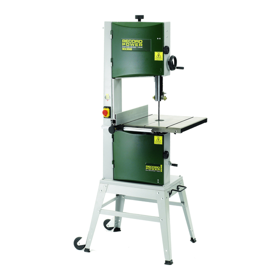
BS350S Premium
14" Bandsaw
Version 3.0
January 2013
It is important to register your product as soon as possible in order to receive efficient after sales
support and be entitled to the full 5 year guarantee. Your statutory rights are not affected.
Kg
Always wear safety glasses when
using woodworking equipment.
To register this product please visit
www.recordpower.info
Please see back cover for contact details.
i
Always read the instructions
provided before using
woodworking equipment.
Kg
Important
For your safety read instructions carefully
before assembling or using this product.
Save this manual for future reference.
Advertisement
Table of Contents

Related Manuals for Record Power BS350S


Summary of Contents for Record Power BS350S
- Page 1 Original Instruction Manual BS350S Premium 14" Bandsaw Version 3.0 January 2013 To register this product please visit www.recordpower.info It is important to register your product as soon as possible in order to receive efficient after sales support and be entitled to the full 5 year guarantee. Your statutory rights are not affected.
-
Page 2: Table Of Contents
Electrical Connection & Wiring Diagram Operation & Bandsawing Practice Dust Extraction Maintenance Trouble Shooting Parts Diagrams Parts List Assembly of the Optional BS350S-W Pedal Wheel Kit 37 EU Declaration of Conformity Consumable Spare Parts Quick Find Description Part Number Part Description Part Number... -
Page 3: Explanation Of Symbols
Explanation of Symbols The symbols and their meanings shown below may be used throughout this manual. Please ensure that you take the appropriate action wherever the warnings are used. Mandatory Instructions Read and fully understand the instruction manual before attempting to use the machine. -
Page 4: General Health & Safety Guidance
General Health & Safety Guidance Ensure that you carefully read and fully understand the 6. The machine should be level and stable at all times instructions in this manual before assembly, installation and • When using a leg stand or cabinet base that is designed to be fitted to use of this product. - Page 5 General Health & Safety Guidance - cont. complete stop. • Use extra supports (roller support stands etc.) for any work pieces large enough to tip when not held down to the table top. • If the work area is to be left unattended, all machinery should be switched ‘OFF’...
-
Page 6: Additional Health & Safety For Bandsaws
General Health & Safety Guidance - cont. • Before each use of the machine, it should be carefully checked to 32. Have your machine repaired by a qualified person determine that it will operate properly and perform its • This machine complies with the relevant safety rules and standards intended function. -
Page 7: Record Power Guarantee
Guarantee should be made directly to Record Power or its Authorised Distributor Record Power guarantees that for a period of 5 years from the date (for details of the Authorised Distributor in your country please see of purchase the components of qualifying Products (see clauses 1.2.1 your Product manual or check www.recordpower.info for details). -
Page 8: Getting To Know Your Bandsaw
1. Getting To Know Your Bandsaw Fig.1 Blade Tensioning Knob Blade Tension Release Cam Handle Rise & Fall Hand Wheel Rise & Fall Lock Knob Blade Blade Tracking Knob Upper Blade Guides Table Tilting Knob Table Motor Rating Plate Rip Fence 100 mm Dust Extraction Port Rip Fence Rail Motor... -
Page 9: Stand & Wheel Kit Assembly
3. Stand & Wheel Kit Assembly 3.1 Stand & Wheel Kit Assembly Fig.3.1 CAUTION! The machine is heavy. Additional help or a suitable lifting device or support will be required for lifting the machine onto the stand. The stand and wheel kit comes as a self assembly unit, Fig.3.1. Stand 1. - Page 10 Fig.3.3 Fig.3.7 Please see section 15 for assembly instructions of the BS350S-W Pedal SHORT MID Wheel Kit. BRACE SUPPORT 3.2 Stand Assembly 1. Locate the first leg and secure it to one of the...
- Page 11 3. Stand & Wheel Kit Assembly - cont. 3.3 Wheel Kit Assembly Fig.3.8 1. Attach the fixed wheels to the rear legs of the machine stand using the M6 x 16 hex bolts, Washers, and M6 nuts provided. Fig 3.8. The rear of the stand is the side which features the medium mid brace support.
- Page 12 3. Stand & Wheel Kit Assembly - cont. 1. Feed the long fixing bolts up through the Fig.3.10 stand and secure the four corners using the washers and bolts provided Fig.3.10. Once LONG FIXING BOLTS this is achieved the whole stand can be fully tightened ready for the bandsaw to be fitted.
-
Page 13: Machine Assembly
4. Machine Assembly 4.1 Unpacking and components included Fig.4.1 The machine is supplied partly assembled. Prior to use, further assembly is required. When unpacking the machine, in addition to the bandsaw itself, the following components are included for the initial assembly Fig.4.1: 1. - Page 14 4. Machine Assembly - cont. 4.2 Rise & fall hand wheel Fig.4.2 Attach the rise and fall hand wheel to the rise and fall shaft and tighten the socket head bolt with a 6 mm hex wrench, then attach the handle and tighten with a 10 mm spanner (See Fig.4.2).
- Page 15 4. Machine Assembly - cont. 4.6 Fitting the fence bar Fig.4.10 Attach the fence bar to the table as shown in Fig. 4.7, ensuring the washers are placed next to the fixing nuts. Use the remaining 2 nuts and washers to secure the fence bar from the underside of the table, Fig. 4.8. Do not fully tighten yet as adjustment may be necessary.
- Page 16 4. Machine Assembly - cont. 4.8 Fitting the fence carrier Fig.4.13 Locate fence carrier onto the fence bar Fig.4.13. 4.9 Fitting the rip fence Slide the rip fence onto the carrier as shown in Fig. 4.14 and tighten the two securing knobs. The fence can be used in the upright position as shown, or the other T slot can be used to give a lower position.
-
Page 17: Setting Table Square To The Saw Blade
5. Setting Table Square to the Saw Blade Fig.5.1 CAUTION! Before carrying out any adjustments or maintenance ensure that the machine is isolated and disconnected from the electricity supply. 5.1 Setting the table stop at 90º to saw blade Tools Required:- Small 90º square (Not supplied) The table can be set at 90º... -
Page 18: Bandsaw Blade Set Up
6. Bandsaw Blade Set Up Fig.6.1 CAUTION! Before carrying out any adjustments or maintenance ensure BLADE TENSIONING KNOB that the machine is isolated and disconnected from the electricity supply. 6.1 Tensioning the blade The blade tensioning knob should be used to increase or decrease tension (See Fig. - Page 19 6. Bandsaw Blade Set Up - cont. Fig.6.4 GUIDE CARRIER CAUTION! Before carrying out any adjustments or maintenance ensure that the machine is isolated and disconnected from the KNURLED NUT electricity supply. 6.3 Adjusting the Upper Guides First check that all of the roller guides are moving freely. To adjust the upper blade guides, first position the guide assembly relative to the blade, by slackening off the hex screw (Fig.6.4A) and moving the guide carrier until the roller guides are just behind the gullets of the blade (See...
-
Page 20: Drive Belt Adjustment & Speed Change
7. Drive Belt Adjustment & Speed Change Fig.7.1 CAUTION! Before carrying out any adjustments or maintenance ensure that the machine is isolated and disconnected from the electricity supply. 7.1 Adjusting the drive belt tension Use the crank handle (See Fig.7.1) to adjust the tension of the drive belt. Rotate the handle anti-clockwise to increase the tension and clockwise to decrease tension. -
Page 21: Electrical Connection & Wiring Diagram
8. Electrical Connection & Wiring Diagram Machines supplied for use in the UK are fitted with a 3 pin plug conforming machine. If replacing the original fuse, always fit a fuse of equivalent rating to BS1363, fitted with a fuse conforming to BS1362 and appropriate to the to the original. -
Page 22: Operation & Bandsawing Practice
Remove the faulty component and replace only with genuine Record Power replacement parts. Any electrical components should only be replaced by a suitably qualified person. To replace a broken blade, please refer to the section of this manual entitled “Band saw Blade Set Up”. - Page 23 9. Operation & Bandsawing Practice - cont. Blade Selection (TPI) - Cont. Material Material Thickness Having selected an appropriate blade for the particular thickness and type <6 mm 6-12 mm 12-25 mm >25mm of material to be sawn, it is essential that the saw blade is allowed to cut Perspex 16 TPI 14 TPI...
- Page 24 3/4” x 3 TPI Skip tooth pattern BB10312-3PACK 1/4”, 3/8” & 5/8” Skip tooth pattern Note: As well as the blades listed, we can also supply bandsaw blades to almost any specification please call Record Power Customer Services in your country. Narrow Blade Wide Blade 9.9 Record Power BS350S Blade Range...
- Page 25 9. Operation & Bandsawing Practice - cont. Ex. 2. Always support round pieces with a wedge or vee block. Take extreme Ex. 5. Jig for accurate repetitive wedges. care as there is a danger that if the work is not secured properly the blade will snatch the work piece, potentially causing it to spin or bounce back at you.
-
Page 26: Dust Extraction
Record Power Extractors be switched off for 20 minutes every hour. 0.5 micron filtration Record Power offer a range of high quality dust extractors, we offer both CX2600 Chip Collector drum and bag type extractors which filter down 0.5 micron providing Large capacity chip collector, with a powerful 0.37 kW induction motor. -
Page 27: Maintenance
11. Maintenance Fig.11.1 HEX SCREW CAUTION! Before carrying out any adjustments or maintenance ensure that the machine is isolated and disconnected from the electricity supply. 11.1 Replacing the bandsaw blade KEEP PLATE Fig.11.2 HAZARD! Take great care when unpacking the bandsaw blade as they are usually folded and can spring out very suddenly with great force. - Page 28 11. Maintenance - cont. Fig.11.4 CAUTION! Before carrying out any adjustments or maintenance ensure that the machine is isolated and disconnected from the electricity supply. 13 mm HUB NUT 11.2 Replacing the drive belt To replace the drive belt simply loosen the tension on the belt using the belt tension handle.
- Page 29 11. Maintenance - cont. 11.4 The table insert The table insert on a bandsaw is a consumable item Fig.11.9 and will Fig.11.9 therefore need replacing periodically. This procedure should be carried out with the bandsaw blade removed. To replace the table insert simply push the old insert out from underneath the table and fit the new one into position.
-
Page 30: Trouble Shooting
1. Check the power cable and fuse. 2. Defective switch. 2. Replace the switch. 3. Doors not closed fully. 3. Ensure both doors are closed fully. 4. Fuse blown. 4. Check and replace the fuse. 5. Defective motor. 5. Replace with genuine Record Power motor. -
Page 31: Parts Diagrams
13. Parts Diagrams Stand with wheel kit Ref No. Description Ref No. Description Rubber shoe D-handle clamp Short mid brace support Hex nut Wheel bracket Long top brace support Hex bolt Hex nut Hex nut Washer Flat washer Hex bolt Washer Hex nut Carriage bolt... - Page 32 13. Parts Diagrams - cont.
- Page 33 13. Parts Diagrams - cont.
- Page 34 13. Parts Diagrams - cont.
-
Page 35: Parts List
14. Parts List Ref No. Description Ref No. Description Blade tension knob Nylon nut M6-1.0 Frame Strain relief Set screw M5-0.8 x 10 Strain relief nut Safety switch Crank handle Flat washer M5 Tension rod Power cord Guide post lock knob Hex nut M8-1.25 Blade tracking knob Pointer... -
Page 36: Eu Declaration Of Conformity
14. Parts List - cont. Ref No. Description Ref No. Description Flat washer M5 Spacer bushing Pointer Bushing Trunnion plate Cap screw M6-1.0 x 16 Rise and fall crank handle Spring washer 6 Hex bolt M8-1.25 x 16 Guide bracket Carriage bolt M6-1.0 x 65 Worm cylinder Table... -
Page 37: Assembly Of The Optional Bs350S-W Pedal Wheel Kit
15. Assembly of the Optional BS350S-W Pedal Wheel Kit Fig.15.1 Pedal Flat washer Hex nut Spring washer Washer Axle Split pin Rotating casters Hex bolt Casters Release catch Hex nut Flat washer Operating frame Brace support bar When fitting the optional pedal wheekit during initial assembly 7. - Page 38 OPERATING FRAME Fig.15.2 Fig.15.10 Fig.15.6 FIXING PIN FLATTENED AREAS RELEASE CATCH PEDAL Fig.15.11 Fig.15.3 Fig.15.7 PEDAL AXLE RELEASE CATCH FIXING PIN Fig.15.8 Fig.15.4 REAR OF BANDSAW Fig.15.5 Fig.15.9 AXLE BRACE SUPPORT BAR...
-
Page 39: Eu Declaration Of Conformity
EU Declaration of Conformity Cert No: EU / BS350S / 1 RECORD POWER LIMITED, Centenary House, 11 Midland Way, Barlborough Links, Chesterfield, Derbyshire S43 4XA declares that the machinery described:- Type: Bandsaw Model No: BS350S Serial No ................. Conforms with the following directives:-... - Page 40 Woodworking Machinery & Accessories United Kingdom Eire Australia New Zealand Record Power Ltd Record Power Ltd Tools 4 Industry Tools 4 Industry Centenary House, 11 Midland Way, Centenary House, 11 Midland Way, Po Box 3844 Po Box 276079 Barlborough Links, Chesterfield,...
Need help?
Do you have a question about the BS350S and is the answer not in the manual?
Questions and answers