
Related Manuals for Record Power BS250


Summary of Contents for Record Power BS250
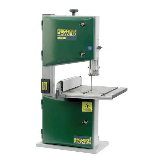
- Page 1 Instruction BS250 Manual Compact Bandsaw IMPORTANT For your safety read instructions carefully before assembling or using this product. Save this manual for future reference.
- Page 3 Contents Terms & Conditions Of Usage Health & Safety Guidance page 4 Additional Safety Instructions For Bandsaws page 5 Record Power Guarantee page 6 EU Declaration Of Conformity page 31 User Manual Getting To Know Your Bandsaw page 7 Machine Specification page 7 Stand &...
-
Page 4: Health & Safety Guidance
Keep proper footing and balance at all times. Should you need advice on the repair or maintenance of this product, our Customer Service Department can be contacted on 0870 770 1777 and will be happy to assist you. Record Power Health & Safety Guidance v1.0... -
Page 5: Additional Safety Instructions For Bandsaws
10. Do not use saw blades which are damaged or deformed. 11. Replace the table insert when it is worn. 12. When cutting round timber use a suitable device to prevent twisting of the workpiece. See section 8 Fig. 8.5. Record Power Bandsaw Safety v1.0... -
Page 6: Record Power Guarantee
2.2.6 This Guarantee extends to the cost of carriage incurred by you returning the product to Record Power as long as it is demonstrated that the defect falls within the terms of this Guarantee and you follow the claims procedure as outlined below;... -
Page 7: Getting To Know Your Bandsaw
Getting To Know Your Bandsaw Fig.1 Blade Tensioning Knob Rise & Fall Knob Rise & Fall Lock Tracking Knob Blade Tracking Knob Lock Upper Blade Guide Motor Rating Plate Mitre Fence Table Tilting Handle Rip Fence 100mm Dust Extraction Port Rip Fence Rail Motor Table... - Page 8 3. Stand & Wheel Kit Assembly (Optional) 3.1 Stand & Wheel Kit Assembly Fig.3.1 CAUTION! The machine is heavy. Additional help or a suitable lifting device or support will be required for lifting the machine onto the stand. The stand and wheel kit comes as a self assembly unit Fig.3.1. Stand 1.
- Page 9 3. Stand & Wheel Kit Assembly (Optional) - cont. Note: When assembling this legstand Fig.3.2 Fig.3.6 Do Not fully tighten the nuts and bolts LONG MID BRACE until the assembly is complete. Finger SUPPORTS tight should be sufficient. 3.2 Stand Assembly LONG TOP BRACE 1.
- Page 10 3. Stand & Wheel Kit Assembly (Optional) - cont. 3.3 Wheel Kit Assembly Fig.3.9 Fig.3.14 1. On the underside of the operating frame, feed the short stem wheels through the pre-drilled holes and secure AXLE with one of the pins and washers provided Fig.3.9.
- Page 11 3. Stand & Wheel Kit Assembly (Optional) - cont. Note Fig.3.17 LONG FIXING BOLTS Fig.3.19 Before fully tightening all of the fixtures on the stand ensure that the long fixing bolts and nuts are fitted through each top corner of the stand. Once this is complete the rest of the stand can be fully tightened and the bandsaw can be fitted.
-
Page 12: Machine Assembly
Machine Assembly 4.1 Unpacking and components included Fig.4.1 The machine is supplied partly assembled. Prior to use, further assembly is required. When unpacking the machine the following components are included for the initial assembly Fig.4.1: 1. 1 x Table 2. 1 x Fence 3. - Page 13 Machine Assembly - cont. Fig.4.1B...
- Page 14 Machine Assembly - cont. 4.4 Fence alignment 1 Adjustment can be made to the fence in relation to being square to the blade. This is done by slackening the four star knobs on the fence rail and adjusting the rails position until the fence is square to the blade.
-
Page 15: Machine Setting
Machine Setting CAUTION! Before carrying out any adjustments or maintenance ensure that the machine is isolated and disconnected from the electricity supply. 5.1 Tilting the table The tilt mechanism will be used when squaring the table to the blade. Tilt the table as follows: Loosen the lock handle on the table trunnion. - Page 16 Machine Setting - cont. CAUTION! Fig.5.4 Before carrying out any adjustments or maintenance ensure that the machine is isolated and disconnected from the electricity supply. 5.4 Tensioning the blade The blade tensioning knob should be used to increase or decrease tension. The only accurate way to check a blade is with a tension meter.
-
Page 17: Bandsaw Blade Set Up
Bandsaw Blade Set Up Fig.6.1 6.1 Adjusting the Upper Guides First check that all of the roller guides are moving freely. To adjust the upper blade guides, position the guide assembly relative to the blade by slackening off the lock nut (Fig.6.1) and moving the guide carrier until the roller guides are just behind the gullets of the blade Fig.6.3. -
Page 18: Connection Of The Electricity Supply
Connection Of The Electricity Supply Once the machine has been correctly assembled and set up, the electricity supply can be connected. The machine can only be connected to a single phase supply. Before connecting the electrical supply ensure that it is the correct voltage, phase and frequency, and that it has sufficient capacity for the machine. -
Page 19: Operation & Bandsawing Practice
Operation & Bandsawing Practice 8.1 Basic bandsawing principles 8.5 Blade selection (TPI) The selection of the best blade configuration (See Fig 8.1) is • The blade cuts on a continuous down stroke. • Slowly feed the workpiece towards the blade, using only necessary for optimum cutting performance. - Page 20 ���������� Please note as well as the blades listed, we can also supply bandsaw blades to almost any specification please call ����������� ����������� ����������� Record Power Customer Services on ������ ������� ��������� 0870 770 1777 for further details. ������� �������...
- Page 21 British blade that can last up to ten times longer than other blades on the market. The following range of blades are available for the BS250. To order any of these blades please contact our Customer Services Department on 0870 770 1777 who will advise you of your nearest retailer or alternatively a mail order supplier.
- Page 22 Operation & Bandsawing Practice - cont. Fig.8.7 8.8 Custom Jigs & Work Support Chamfered pieces can be cut squarely using an A bandsaw is one of the most versatile machines in the additional support jig on the opposite side of the workshop and with careful lateral thinking many problems work piece to the fence.
-
Page 23: Dust Extraction
9.2 Record Power Extractors suction but in this mode the extractor must be switched off for Record Power offer a range of high quality dust extractors, 20 minutes every hour. starting at the single motor 45 litre RSDE1 right up to the 200 DX5000 High Filtration Dust Extractor litre twin motor DX5000. -
Page 24: Maintenance
Maintenance CAUTION! Fig.10.1 Before carrying out any adjustments or maintenance ensure that the machine is isolated and disconnected from the electricity supply. 10.1 Replacing the bandsaw blade HAZARD! Take great care when unpacking the bandsaw blade as they are usually folded and can spring out very suddenly with great force. -
Page 25: Motor Pulley
Maintenance - cont. CAUTION! Fig.10.4 Fig.10.9 Before carrying out any adjustments or maintenance ensure that the machine is isolated and disconnected from the electricity supply. 10.2 Replacing the drive belt Note: Circlip pliers are required for this procedure To replace the drive belt slacken the tension on the belt by loosening the motor pivot Allen bolt on the back of the machine, lifting the motor and re-... - Page 26 10.4 The table insert Fig.10.9 The table insert on a bandsaw is a consumable item Fig.10.9 and will therefore need replacing periodically. This procedure should be carried out with the bandsaw blade removed. To replace the table insert simply push the old insert out from underneath the table and fit the new one into position.
- Page 27 10.9 Wiring Information Replacing Power Supply Cable Replacement of the power supply cable should only be done by a qualified electrician. ���������������������� � � ���� ������������� � � ������������� ����� � � ��� ���������� � � ����� � � ������������� ��������...
-
Page 28: Parts Diagrams
Parts Diagrams Stand & Wheel Kit Ref No. Description Pedal Hex screw M6x35 Nut M6 Long top brace support Washer 10mm Axle Fixing pins Short stem wheels Pan Hd screw M4x30 Long stem wheels Release pedal Legs Self nut M4 Operating frame Brace support bar Short top brace support... - Page 29 Parts Diagrams - cont.
-
Page 30: Parts List
Parts List Ref No. Description Ref No. Description Bandsaw Frame Hexagonal nut with flange – M8 Upper Door Carriage bolt – M6 x 16mm Lower Door Hexagonal nut with flange – M6 Upper Wheel Washer Ball Bearing - 80100 Hexagonal socket head cap screw – M8 x 30mm Wing nut J-belt Pan head self tapping screw –... -
Page 31: Eu Declaration Of Conformity
EU Declaration of Conformity Cert No: EU / BS250 / 1 RECORD POWER LIMITED, Unit B, Ireland Industrial Est. Adelphi Way, Staveley, Chesterfield S43 3LS declares that the machinery described:- Type: Bandsaw Model No: BS250 Serial No ................. Conforms with the following directives:-... - Page 32 Woodworking Machines & Accessories Record Power Limited Telephone: 0870 770 1777 Email: sales@recordpower.co.uk Unit B, Adelphi Way http://www.recordpower.co.uk Facsimile: 0870 770 1888 Ireland Industrial Est. Staveley S43 3LS...
Need help?
Do you have a question about the BS250 and is the answer not in the manual?
Questions and answers
what is the length of the blade on a bs250?
The length of the blade on the Record Power BS250 is 1790 mm (70 1/2 inches).
This answer is automatically generated