Table of Contents
Advertisement
Quick Links
Original Instruction Manual
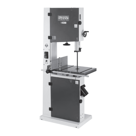
SABRE-450
18" Bandsaw
Version 3.5
March 2022
It is important to register your product as soon as possible in order to receive efficient after sales
support and be entitled to the full 5 year guarantee. Your statutory rights are not affected.
Kg
Always wear safety glasses when
using woodworking equipment.
To register this product please visit
www.recordpower.info
Please see back cover for contact details.
Important
i
For your safety read instructions carefully before
assembling or using this product.
Always read the instructions
provided before using
Save this manual for future reference.
woodworking equipment.
Advertisement
Table of Contents

Related Manuals for Record Power SABRE-450


Summary of Contents for Record Power SABRE-450
- Page 1 Original Instruction Manual SABRE-450 18" Bandsaw Version 3.5 March 2022 To register this product please visit www.recordpower.info It is important to register your product as soon as possible in order to receive efficient after sales support and be entitled to the full 5 year guarantee. Your statutory rights are not affected.
-
Page 2: Table Of Contents
Contents Explanation of Symbols General Health and Safety Guidance Additional Health and Safety Guidance for Bandsaws Record Power Guarantee Getting to Know Your Bandsaw Specifications Contents of the Package Assembly Assembly of the Optional 67052 Table Extension 10 Assembly of the Optional 68050 Wheel Kit... -
Page 3: Explanation Of Symbols
1. Explanation of Symbols THE SYMBOLS AND THEIR MEANINGS SHOWN BELOW MAY BE USED THROUGHOUT THIS MANUAL. PLEASE ENSURE THAT YOU TAKE THE APPROPRIATE ACTION WHEREVER THE WARNINGS ARE USED. Mandatory Instructions Read and fully understand the instruction manual before attempting to use the machine. Indicates an instruction that requires particular attention Wear protective eyewear Use respiratory protective equipment... -
Page 4: General Health And Safety Guidance
2. General Health and Safety Guidance Ensure that you carefully read and fully understand the 6. The machine should be level and stable at all times instructions in this manual before assembly, installation and use • When using a leg stand or cabinet base that is designed to be fitted to of this product. - Page 5 2. General Health and Safety Guidance • If the work area is to be left unattended, all machinery should be additional support for a work piece that is longer or wider than the basic switched ‘OFF’ and isolated from the mains power supply. table, or to help feed, support, or pull the work piece.
-
Page 6: Additional Health And Safety Guidance For Bandsaws
2. General Health and Safety Guidance • A guard or other part that is damaged should be properly repaired qualified persons using original spare parts should carry out repairs. or replaced by a qualified person unless otherwise indicated in this Failure to do this may result in considerable danger to the user and instruction manual. -
Page 7: Record Power Guarantee
Guarantee should be made directly to Record Power or its Authorised Distributor Record Power guarantees that for a period of 5 years from the date (for details of the Authorised Distributor in your country please see of purchase the components of qualifying Products (see clauses 1.2.1 your Product manual or check www.recordpower.info for details). -
Page 8: Getting To Know Your Bandsaw
5. Getting to Know Your Bandsaw On / off switch Dust extraction port Blade tracking lock Rip fence assembly Lower door knob Blade tension lever Blade tensioning knob Table locking lever Table tilt box wrench Upper door knob Trunnion Motor Upper blade guides Blade guide position hand wheel Dust extraction port... -
Page 9: Contents Of The Package
7. Contents of the Package SABRE-450 bandsaw Push stick M6 x 30 hex socket head screw Table with levelling pin attached Hand wheel M6 nut Hex head socket screws Rip fence 3 mm hex wrench Washers Tool holder 4 mm hex wrench... -
Page 10: Assembly
8. Assembly The table trunnion has 4 holes as shown in Fig 8.1 and the underside of Fig 8.1 the table has 4 corresponding threaded holes as shown in Fig 8.2. Place the table onto the trunnion, taking care to pass the blade through the table slot without damaging it. - Page 11 8. Assembly Place the M8 nut onto the M8 x 50 hex head bolt and attach to the Fig 8.6 underside of the table as shown in Fig 8.6. This bolt acts as a table stop to ensure the table returns to the correct position when it is required to be at 90º...
- Page 12 8. Assembly Ensure the rip fence rail is parallel to the table by measuring the Fig 8.11 distance between them at one end as shown in Fig 8.11 and ensure the measurement is the same at the opposite end as shown in Fig 8.12. Important: Ensure at this stage the table levelling pin is installed as shown in Fig 8.13.
- Page 13 8. Assembly Fitting the Fence Fig 8.16 Place the rip fence mount onto the rail as shown in Fig 8.16. Slide the rip fence onto the mount as shown in Fig 8.17. Ensure the rip fence is placed fully onto the mount and locates over the protrusion as shown in Fig 8.18.
- Page 14 8. Assembly The fence features a pad at each end as shown in Fig 8.21. This raises the Fig 8.21 fence from the table to minimise contact and improve travel of the fence across the table and mitre slot. The height of the fence should be parallel with the table as shown in Fig 8.22.
- Page 15 8. Assembly Aligning the Fence with the Blade Fig 8.26 For accurate cutting the rip fence must be parallel to the blade as shown in Fig 8.26. The fence mount features a cam-mechanism adjustment for quick and easy alignment. Loosen the lock knob as shown in Fig 8.19 and use the adjustment knob to move the fence.
- Page 16 8. Assembly Place the upper hand wheel onto the shaft as shown in Fig 8.31, ensuring Fig 8.31 the blind set screw is positioned over the flattened area. Tighten the blind set screw to secure the hand wheel in place using a 3 mm hex wrench. Fitting the Hanging Bolts for the Optional Jockey Bar Place a nut on each hanging bolt leaving approximately 6 mm of thread visible.
- Page 17 8. Assembly The tool holder is used for storing the hex wrenches supplied with the Fig 8.36 machine as shown in Fig 8.36. Fitting the Re-Saw Bar The re-saw bar can be used when cutting timber which is prone to variations in density and grain direction, particularly larger pieces.
-
Page 18: Assembly Of The Optional 67052 Table Extension
9. Assembly of the Optional 67052 Table Extension Before attaching the table to the bandsaw check that all the contents of the package are present. Description Quantity SABRE sheet metal table extension M8 x 25 bolt Medium washer Small washer M8 nut M6 nut M6 x 16 blind screw set... - Page 19 9. Assembly of the Optional 67052 Table Extension Fig 9.3 The assembly procedure is the same for both positions. To attach the extension to the side of the table, use the holes shown in Fig 9.3 and Fig 9.4. To attach to the rear of the table use the holes shown in Fig 9.5 and Fig 9.6.
- Page 20 9. Assembly of the Optional 67052 Table Extension Fig 9.7 Fit the 3 blind set screws to the extension in the locations shown in Fig 9.7 and then the M6 nuts. Attach the extension to the main table as shown in Fig 9.8 and Fig 9.9, using the M8 x 25 bolts, medium washers and M8 nuts.
- Page 21 9. Assembly of the Optional 67052 Table Extension Parts List and Diagram Description Part Number Quantity SABRE sheet metal table 67052 extension M8 x 25 bolt 99289 Medium washer 99226 Small washer 99311 M8 nut CVG130-105 M6 nut 99312 M6 x 16 blind screw set 99310...
-
Page 22: Assembly Of The Optional 68050 Wheel Kit
10. Assembly of the Optional 68050 Wheel Kit Key No. Description Shaft Wheel Flat washer Split cotter pin Bracket Tow bar assembly Flat washer Hex bolt Hex nut Tools Required for Assembly 13 mm or Pliers Adjustable Wrench... -
Page 23: Operation And Bandsawing Practice
11. Operation and Bandsawing Practice Fig 11.1 Caution: Before carrying out any adjustments or maintenance ensure that the machine is isolated and disconnected from the electricity supply. Changing the Bandsaw Blade Open the upper and lower band wheel box doors. Remove the securing table levelling pin as shown in Fig 11.1 to allow the blade to be passed through the front of the table as it is removed. - Page 24 11. Operation and Bandsawing Practice Tensioning the Bandsaw Blade Fig 11.6 Re-engage the cam tension lever and if necessary adjust the tension knob to apply the correct tension to the blade. To check the tension of the blade, set the blade guides to their highest position and apply a reasonable amount of pressure using a push stick.
- Page 25 11. Operation and Bandsawing Practice To adjust the tracking, loosen the tracking lock knob and adjust the tracking Fig 11.11 Tracking lock knob knob as shown in Fig 11.11. Turn the knob clockwise to move the blade towards the back of the band wheel and anti-clockwise to move it towards Tracking the front.
- Page 26 11. Operation and Bandsawing Practice The side guides must now be positioned as close to either side of the blade Fig 11.16 as possible. Loosen the side guide locks shown in Fig 11.15, position the guides correctly by moving the guide shafts then re-tighten the locks as shown in Fig 11.16.
- Page 27 11. Operation and Bandsawing Practice The assembly must allow the workpiece to pass beneath it as shown in Fig 11.21 Fig 11.21. Turning the Bandsaw On and Off The bandsaw is fitted with a no-volt release switch which ensures it will not unintentionally re-start after a power failure, Fig 11.22.
- Page 28 Remove the faulty your country. component and replace only with genuine Record Power replacement The table provides a guide to selection only. Exact tooth configurations parts. Any electrical components should only be replaced by a suitably are not always available, nor are all blade configurations covered, but the qualified person.
- Page 29 11. Operation and Bandsawing Practice Blade Selection (TPI) - Cont. Material Material Thickness Having selected an appropriate blade for the particular thickness and type <6 mm 6-12 mm 12-25 mm >25mm of material to be sawn, it is essential that the saw blade is allowed to cut Perspex 16 TPI 14 TPI...
- Page 30 STRAIGHT CUT / on the market. To order any of these blades please CONTOUR LARGE contact Record Power Customer Services in your CONTOUR country who will advise you of your nearest retailer or alternatively a mail order supplier. Blade Spec...
-
Page 31: Maintenance
12. Maintenance Fig 12.1 Caution: Before carrying out any adjustments or maintenance ensure that the machine is isolated and disconnected from the electrical supply Replacing the Drive Belt To replace the drive belt first remove the band saw blade following section 11 on changing the bandsaw blade. - Page 32 12. Maintenance Ensure that the V grooves of the belt mate with the V grooves of the pulleys Fig 12.5 as shown in Fig 12.5. Replacing the Band Wheel Bearings Drive belt The bandsaw blade and wheels must be removed before replacing the bearings.
- Page 33 12. Maintenance Replacing Band Wheel Tyres Fig 12.10 The band wheels have rubber tyres fitted to protect the teeth of the blade when in use and also provide grip to stop the blade slipping. Regularly Rubber inspect the tyres for wear and damage and replace if necessary. tyre Remove the wheel from the bandsaw and ease the existing tyre from the rim, taking care not to damage the bandwheel.
- Page 34 Regular cleaning of the table will ensure optimum performance of the machine. Remove all dust and resin using white spirit then coat the table with Record Power CWA195 Silicone Spray. The silicone spray will repel dust and resin, helping the timber to move freely on the table.
- Page 35 If replacement parts are needed, please contact Record Power Ltd or their representative in your country for further assistance.
-
Page 36: Dust Extraction
90 litre capacity, 1 kW twin or triple motor, 0.5 micron filtration. Includes hose. Record Power Dust Extraction Machines Below is a summary of the Record Power range. Please visit your local stockist CGV486 CamVac Series Heavy Duty Extractor or go online for full details. -
Page 37: Troubleshooting
14. Troubleshooting Problem Cause Solution Will not cut in a straight line. 1. Blade is blunt. 1. Change blade. 2. Blade guides set too high. 2. Adjust blade guides. 3. Blade tension incorrect. 3. Adjust blade tension. 4. Fence aligned incorrectly. 4. -
Page 38: Electrical Connection And Wiring Diagram
15. Electrical Connection and Wiring Diagram Machines supplied for use in the UK are fitted with a 3 pin plug conforming machine. If replacing the original fuse, always fit a fuse of equivalent rating to BS1363, fitted with a fuse conforming to BS1362 and appropriate to the to the original. -
Page 39: Parts Diagrams And Lists
16. Parts Diagrams and Lists Frame Assembly... - Page 40 16. Parts Diagrams and Lists...
- Page 41 16. Parts Diagrams and Lists Driving System Assembly No Part number Description 1-JMBS1801021001-053Z Upper wheel 1-JXBS1804021002 Tyre 1-CLP47GB893D1B Circlip ring 1-JL26030008 Spacer bushing 1-BRG6204-2RSGB276 Bearing 1-JXPS1202070005 Washer 1-M8X16GB70D1Z Hex socket head screw 1-JMBS1801020002 Blade 1-JMBS1801022001-053Z Lower wheel 1-JL46020005 Multi-vee belt 1-JMBS1801020004B Motor pulley 1-M8X8GB80B12D9...
- Page 42 16. Parts Diagrams and Lists Table Assembly No Part number Description No Part number Description 1-M8X16GB70D1Z Hex socket head screw 1-M6X12GB77B12D9 Set screw M6 x 12 1-WSH8GB97D1Z Flat washer 1-JMBS1403030005 Support bracket 1-JMBS1801030002-053W Extension table 1-WSH10GB97D1B Flat washer 1-M6X8GB77B12D9 Hex set screw M6 x 8 1-WSH10GB93B Spring washer 1-JMBS1404030002...
- Page 43 16. Parts Diagrams and Lists Blade Tension Assembly No Part number Description No Part number Description 1-M6X30GB70D1Z Hex socket head screw 1-SGSL-D125-d12A Handwheel 1-M6GB6170Z Hex nut M6 1-BRG51105GB301 Bearing 1-M8X10GB70D1Z Hex socket head screw 1-JL26030018 Tension lever with riser block 1-WSH8GB5287Z Large washer 1-BRG51201GB301...
- Page 44 16. Parts Diagrams and Lists Upper Guide Assembly 39 38 No Part number Description No Part number Description 1-JMBS1801050006-001S Locking handle M10 1-JMBS1801052003 Bearing sleeve 1-M8X20GB70D2B Hex bolt M8 x 20 1-BRG6202-2RSGB276 Bearing 1-WSH8GB96D1B Large washer 1-WSH8GB96D1B Large washer 1-JL26040008 Guide bracket 1-JMBS1403014003 Guide shaft...
- Page 45 16. Parts Diagrams and Lists Rip Fence Assembly Part number Description 1-JMBS1403060009-001S Adjust handle 1-JMBS1403060010-001S Drift locking handle 1-M8X10GB80B Hex screw M8 x 10 1-JMBS1403060004 1-WSH10GB97D1Z Flat washer 1-M10GB889D1Z Hex locking nut M10 1-JMBS1403060003-001S Fence locking handle 1-WSH8GB96D1Z Large washer 1-JMBS1403060001-053W Fence carrier 1-JMBS1401063100...
- Page 46 Andrew Greensted Managing Director Technical file held by Andrew Greensted, Record Power Ltd, Centenary House, 11 Midland Way, Barlborough Links, Chesterfield, Derbyshire, S43 4XA, United Kingdom Record Power B.V., Verlengde Poolseweg 16, 4818 CL BREDA, Netherlands, Tel: +31 76 52 44 766...
- Page 48 Woodworking Machinery and Accessories Record Power Ltd, Centenary House, 11 Midland Way, Barlborough Links, Chesterfield, Derbyshire S43 4XA Tel: +44 (0) 1246 571 020 Fax: +44 (0) 1246 571 030 www.recordpower.co.uk To register a product and find your local stockist visit recordpower.info...
Need help?
Do you have a question about the SABRE-450 and is the answer not in the manual?
Questions and answers