
Summary of Contents for Smartek Vision Giganetix GC Series
- Page 1 User Manual Giganetix Camera Family SMARTEK Vision Business Class Products at Economy Prices www.SMARTEKvision.com SMARTEK d.o.o. 2015, information is subject to change without prior notice, Version 2.1.4 from 2015-02-13...
- Page 2 Users using or selling these products for use in such applications do so at their own risk and agree to fully indemnify SMARTEK d.o.o. for any damages resulting from any improper use or sale. www.SMARTEKvision.com SMARTEK d.o.o. 2015, information is subject to change without prior notice, Version 2.1.4 from 2015-02-13...
- Page 3 However there may be unintentional and occasional errors for which we apologize. SMARTEK d.o.o. makes no representations, warranties or assurances of any kind as to the accuracy, currency or completeness of the information provided. SMARTEK d.o.o. shall not be liable of any damages or injury resulting from your reliance on any information provided in this document.
-
Page 4: Table Of Contents
2.4.3 RoHS ..........SMARTEK Vision Giganetix User Manual Version 2.1.4... - Page 5 5.1 Smartek GigE Vision Filter Driver ........
- Page 6 5.4.3 Supported Pixel Formats for Color Cameras ......146 5.4.4 Pixel Formats Supported by the SMARTEK Vision Giganetix camera family ..148 5.5 Chunk Data .
-
Page 7: Description Of Product Family
Software Development Kit as well as a large number of 3rd-party libraries compliant to the GigE Vision Standard. To use these devices with other software than provided by SMARTEK Vision, please check their user guides. -
Page 8: Precautions
Operating the camera outside of the specifications can cause to permanent damage. Further electrical specifications can be found in chapter 2.1 - Mechanical and Electrical specifications. SMARTEK Vision Giganetix User Manual Version 2.1.4... -
Page 9: Supported Industry Standards
XML description - file based on the GenICam standard which provides the mapping between a device feature and the device register implementing the feature. SMARTEK Vision Giganetix User Manual Version 2.1.4... -
Page 10: Genicam
The GenApi module of the GenICam standard defines how to write a camera description file that describes a specific camera’s mapping. For detailed information about this convention visit www.emva.org. SMARTEK Vision Giganetix User Manual Version 2.1.4... -
Page 11: C-Mount
Decrease the risk of electrostatic discharge by taking the following measures: Use conductive materials at the point of installation. Use suitable clothing (cotton) and shoes. Control the humidity in your environment. Low humidity can cause ESD problems. SMARTEK Vision Giganetix User Manual Version 2.1.4... -
Page 12: Supported Third-Party Software
Native (GigEVision interface) Cognex Vision Pro Native (GigEVision interface) Matrox Imaging Library Native (GigEVision interface) MVTec Halcon National Instruments National Instruments IMAQdx (Plugin) LabView Plugin provided by SMARTEK Vision Scorpion Vision Table 2: Third-Party Software SMARTEK Vision Giganetix User Manual Version 2.1.4... -
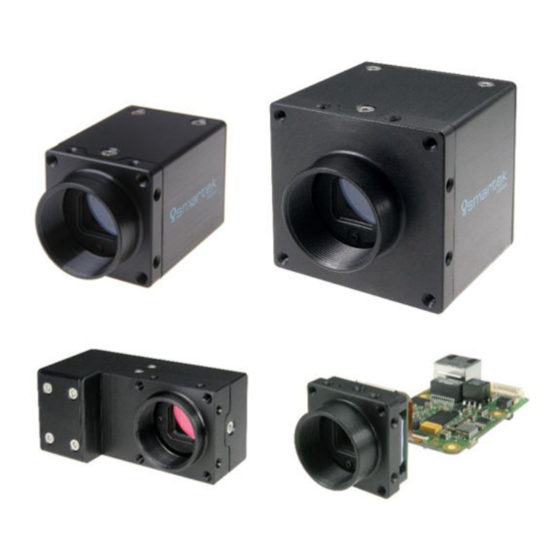
Page 13: Smartek Vision Giganetix Camera Models
Enhanced version of the Giganetix Camera in an adapted mechanical GCP (standard housing) design providing a set of high-end sensors and increased hardware capabilities, as well as Power over Ethernet by default. Table 3: Giganetix Family Camera Lines SMARTEK Vision Giganetix User Manual Version 2.1.4... -
Page 14: Mechanical And Electrical Specifications
Circular Hirose 12 pin (Power and I/O-Interface) 2 input channels, opto-isolated Digital input 2 output channels, opto-isolated Digital output CE, FCC, RoHS, GigE Vision, GenICam, PoE (IEEE802.3af) Conformity measured at camera housing Table 4: Mechanical and electrical specifications SMARTEK Vision Giganetix User Manual Version 2.1.4... - Page 15 2 SMARTEK Vision Giganetix Camera Models 2.1.1.1 Technical Drawings All models with PoE: RJ45 jack is 180° rotated Figure 2: Technical measures of standard camera housing (all dimensions are in mm [inch]) SMARTEK Vision Giganetix User Manual Version 2.1.4...
-
Page 16: Giganetix With 90 ◦ Angled Housing (Gc-S90 Series)
Circular Hirose 12 pin (Power and I/O-Interface) 2 input channels, opto-isolated Digital input 2 output channels, opto-isolated Digital output CE, FCC, RoHS, GigE Vision, GenICam Conformity measured at camera housing Table 5: Mechanical and electrical specifications SMARTEK Vision Giganetix User Manual Version 2.1.4... - Page 17 2 SMARTEK Vision Giganetix Camera Models 2.1.2.1 Technical Drawings 36,60 36,00 24,50 28,00 7,50 20,00 17,50 3,00 29,00 M3,00 75,00 20,00 ◦ Figure 4: Technical measures of angled 90 camera housing (all dimensions are in mm [inch]) SMARTEK Vision Giganetix User Manual Version 2.1.4...
-
Page 18: Giganetix Board Level (Gc-Bl Series)
Circular Hirose 12 pin (Power and I/O-Interface) 2 input channels, opto-isolated Digital input 2 output channels, opto-isolated Digital output RoHS, GigE Vision, GenICam, PoE (IEEE802.3af) Conformity measured at the direct board environment Table 6: Mechanical and electrical specifications SMARTEK Vision Giganetix User Manual Version 2.1.4... - Page 19 Discharge yourself on a grounded body before touching Work in a static-safe work area on an antistatic mat Wear an antistatic-wrist strap the whole time handling the camera boards Do not hold any of the camera’s components to you clothing SMARTEK Vision Giganetix User Manual Version 2.1.4...
- Page 20 Avoid any mechanical forces like torsion, tension and compression, e.g. by mounting the boards or the cabling. Make sure that no forces are induced to the connectors by using sufficient cable pull reliefs. SMARTEK Vision Giganetix User Manual Version 2.1.4...
- Page 21 35,00 0,72 26,20 18,40 1,14 29,00 0,51 13,00 12 x M3x0.5 - 6H 5.00 4,00 0,16 X 90° Figure 7: Technical measures of board level sensor head (all dimensions are in mm [inch]) SMARTEK Vision Giganetix User Manual Version 2.1.4...
- Page 22 2 SMARTEK Vision Giganetix Camera Models Mainboard Dimensions: 1,69 43,00 1,42 3,00 0,12 THRU 36,00 Figure 8: Technical measures of board level mainboard (all dimensions are in mm [inch]) SMARTEK Vision Giganetix User Manual Version 2.1.4...
-
Page 23: Giganetix Plus Camera With Standard Housing (Gcp Series)
Circular Hirose 12 pin (Power and I/O-Interface) 2 input channels, opto-isolated Digital input 2 output channels, opto-isolated Digital output CE, FCC, RoHS, GigE Vision, GenICam, PoE (IEEE802.3af) Conformity measured at camera housing Table 7: Mechanical and electrical specifications SMARTEK Vision Giganetix User Manual Version 2.1.4... - Page 24 2 SMARTEK Vision Giganetix Camera Models 2.1.4.1 Technical Drawings 1,97 0,51 50,00 13,00 1,67 42,50 0,79 20,00 M3x0.5 - 6H 5.00[0.20] Figure 10: Technical measures of GCP camera with standard housing (all dimensions are in mm [inch]) SMARTEK Vision Giganetix User Manual Version 2.1.4...
-
Page 25: Sensor Information And Technical Specification (All Models Separate)
Free run, external and software trigger (single shot, multi shot) Exposure control Freely programmable via GigE Vision interface Power consumption (aux. / 12V) 2.3W 2.3W 2.3W Power consumption (PoE) 3.0W Not supported 3.0W Table 8: Model specific specification of GC1281M SMARTEK Vision Giganetix User Manual Version 2.1.4... - Page 26 2 SMARTEK Vision Giganetix Camera Models Relative Response 1050 Wavelength (nm) Figure 11: Relative response of GC1281 Monochrome (from sensor datasheet) SMARTEK Vision Giganetix User Manual Version 2.1.4...
-
Page 27: Gc2041C
Power consumption (aux. / 12V) 2.2W 2.2W 2.2W Power consumption (PoE) 2.8W Not supported 2.8W Table 9: Model specific specification of GC2041C Relative Response Wavelength (nm) Figure 12: Relative response of GC2041 Color (from sensor datasheet) SMARTEK Vision Giganetix User Manual Version 2.1.4... -
Page 28: Gc2591M / Gc2591C
Free run, external and software trigger (single shot, multi shot) Exposure control Freely programmable via GigE Vision interface Power consumption (aux. / 12V) 2.2W 2.2W 2.2W Power consumption (PoE) 3.0W Not supported 3.0W Table 10: Model specific specification of GC2591 SMARTEK Vision Giganetix User Manual Version 2.1.4... - Page 29 2 SMARTEK Vision Giganetix Camera Models Relative Response 1050 Wavelength (nm) Figure 13: Relative response of GC2591 Monochrome (from sensor datasheet) Wavelength (nm) Figure 14: Relative response of GC2591 Color (from sensor datasheet) SMARTEK Vision Giganetix User Manual Version 2.1.4...
-
Page 30: Gc3851M / Gc3851C
Free run, external and software trigger (single shot, multi shot) Exposure control Freely programmable via GigE Vision interface Power consumption (aux. / 12V) 2.5W 2.5W 2.5W Power consumption (PoE) 3.2W Not supported 3.2W Table 11: Model specific specification of GC3851 SMARTEK Vision Giganetix User Manual Version 2.1.4... - Page 31 2 SMARTEK Vision Giganetix Camera Models Relative Response 1050 Wavelength (nm) Figure 15: Relative response of GC3851 Monochrome (from sensor datasheet) Wavelength (nm) Figure 16: Relative response of GC3851 Color (from sensor datasheet) SMARTEK Vision Giganetix User Manual Version 2.1.4...
-
Page 32: Gc651M / Gc651C
Free run, external and software trigger (single shot, multi shot) Exposure control Freely programmable via GigE Vision interface Power consumption (aux. / 12V) 2.3W 2.3W 2.3W Power consumption (PoE) 3.0W Not supported 3.0W Table 12: Model specific specification of GC651MC SMARTEK Vision Giganetix User Manual Version 2.1.4... - Page 33 2 SMARTEK Vision Giganetix Camera Models Relative Response 1050 Wavelength (nm) Figure 17: Relative response of GC651 Monochrome (from sensor datasheet) Wavelength (nm) Figure 18: Relative response of GC651 Color (from sensor datasheet) SMARTEK Vision Giganetix User Manual Version 2.1.4...
-
Page 34: Gc652M / Gc652C
Free run, external and software trigger (single shot, multi shot) Exposure control Freely programmable via GigE Vision interface Power consumption (aux. / 12V) 2.6W 2.6W 2.5W Power consumption (PoE) 3.2W Not supported 3.2W Table 13: Model specific specification of GC652 SMARTEK Vision Giganetix User Manual Version 2.1.4... - Page 35 2 SMARTEK Vision Giganetix Camera Models Relative Response 1050 Wavelength (nm) Figure 19: Relative response of GC652 Monochrome (from sensor datasheet) Wavelength (nm) Figure 20: Relative response of GC652 Color (from sensor datasheet) SMARTEK Vision Giganetix User Manual Version 2.1.4...
-
Page 36: Gc653M / Gc653C
Free run, external and software trigger (single shot, multi shot) Exposure control Freely programmable via GigE Vision interface Power consumption (aux. / 12V) 2.6W 2.6W 2.5W Power consumption (PoE) 3.2W Not supported 3.2W Table 14: Model specific specification of GC653 SMARTEK Vision Giganetix User Manual Version 2.1.4... - Page 37 2 SMARTEK Vision Giganetix Camera Models Relative Response 1050 Wavelength (nm) Figure 21: Relative response of GC653 Monochrome (from sensor datasheet) Wavelength (nm) Figure 22: Relative response of GC653 Color (from sensor datasheet) SMARTEK Vision Giganetix User Manual Version 2.1.4...
-
Page 38: Gc781M / Gc781C
Free run, external and software trigger (single shot, multi shot) Exposure control Freely programmable via GigE Vision interface Power consumption (aux. / 12V) 2.6W 2.6W 2.5W Power consumption (PoE) 3.2W Not supported 3.2W Table 15: Model specific specification of GC781 SMARTEK Vision Giganetix User Manual Version 2.1.4... - Page 39 2 SMARTEK Vision Giganetix Camera Models Relative Response 1050 Wavelength (nm) Figure 23: Relative response of GC781 Monochrome (from sensor datasheet) Wavelength (nm) Figure 24: Relative response of GC781 Color (from sensor datasheet) SMARTEK Vision Giganetix User Manual Version 2.1.4...
-
Page 40: Gc1031M / Gc1031C
Free run, external and software trigger (single shot, multi shot) Exposure control Freely programmable via GigE Vision interface Power consumption (aux. / 12V) 2.2W 2.2W 2.2W Power consumption (PoE) 3.0W Not supported 3.0W Table 16: Model specific specification of GC1031 SMARTEK Vision Giganetix User Manual Version 2.1.4... - Page 41 2 SMARTEK Vision Giganetix Camera Models Relative Response 1050 Wavelength (nm) Figure 25: Relative response of GC1031 Monochrome (from sensor datasheet) Wavelength (nm) Figure 26: Relative response of GC1031 Color (from sensor datasheet) SMARTEK Vision Giganetix User Manual Version 2.1.4...
-
Page 42: Gc1291M / Gc1291C
Free run, external and software trigger (single shot, multi shot) Exposure control Freely programmable via GigE Vision interface Power consumption (aux. / 12V) 2.5W 2.5W 2.5W Power consumption (PoE) 3.2W Not supported 3.2W Table 17: Model specific specification of GC1291 SMARTEK Vision Giganetix User Manual Version 2.1.4... - Page 43 2 SMARTEK Vision Giganetix Camera Models Relative Response 1050 Wavelength (nm) Figure 27: Relative response of GC1291 Monochrome (from sensor datasheet) Wavelength (nm) Figure 28: Relative response of GC1291 Color (from sensor datasheet) SMARTEK Vision Giganetix User Manual Version 2.1.4...
-
Page 44: Gc1391M / Gc1391C
Free run, external and software trigger (single shot, multi shot) Exposure control Freely programmable via GigE Vision interface Power consumption (aux. / 12V) 2.5W 2.5W 2.5W Power consumption (PoE) 3.2W Not supported 3.2W Table 18: Model specific specification of GC1391 SMARTEK Vision Giganetix User Manual Version 2.1.4... - Page 45 2 SMARTEK Vision Giganetix Camera Models Relative Response 1050 Wavelength (nm) Figure 29: Relative response of GC1391 Monochrome (from sensor datasheet) Wavelength (nm) Figure 30: Relative response of GC1391 Color (from sensor datasheet) SMARTEK Vision Giganetix User Manual Version 2.1.4...
-
Page 46: Gc1392M / Gc1392C
Free run, external and software trigger (single shot, multi shot) Exposure control Freely programmable via GigE Vision interface Power consumption (aux. / 12V) 2.8W 2.8W 2.8W Power consumption (PoE) 3.5W Not supported 3.5W Table 19: Model specific specification of GC1392 SMARTEK Vision Giganetix User Manual Version 2.1.4... - Page 47 2 SMARTEK Vision Giganetix Camera Models Relative Response 1050 Wavelength (nm) Figure 31: Relative response of GC1392 Monochrome (from sensor datasheet) Wavelength (nm) Figure 32: Relative response of GC1392 Color (from sensor datasheet) SMARTEK Vision Giganetix User Manual Version 2.1.4...
-
Page 48: Gc1621M / Gc1621C
Free run, external and software trigger (single shot, multi shot) Exposure control Freely programmable via GigE Vision interface Power consumption (aux. / 12V) 2.7W 2.7W 2.7W Power consumption (PoE) 3.4W Not supported 3.4W Table 20: Model specific specification of GC1621 SMARTEK Vision Giganetix User Manual Version 2.1.4... - Page 49 2 SMARTEK Vision Giganetix Camera Models Relative Response 1050 Wavelength (nm) Figure 33: Relative response of GC1621 Monochrome (from sensor datasheet) Wavelength (nm) Figure 34: Relative response of GC1621 Color (from sensor datasheet) SMARTEK Vision Giganetix User Manual Version 2.1.4...
-
Page 50: Gc2441M / Gc2441C
Free run, external and software trigger (single shot, multi shot) Exposure control Freely programmable via GigE Vision interface Power consumption (aux. / 12V) 3.6W 3.6W 3.6W Power consumption (PoE) Not supported Not supported 4.5W Table 21: Model specific specification of GC2441 SMARTEK Vision Giganetix User Manual Version 2.1.4... - Page 51 2 SMARTEK Vision Giganetix Camera Models Relative Response 1050 Wavelength (nm) Figure 35: Relative response of GC2441 Monochrome (from sensor datasheet) Wavelength (nm) Figure 36: Relative response of GC2441 Color (from sensor datasheet) SMARTEK Vision Giganetix User Manual Version 2.1.4...
-
Page 52: Gc1021M / Gc1021C
Free run, external and software trigger (single shot, multi shot) Exposure control Freely programmable via GigE Vision interface Power consumption (aux. / 12V) 3.4W 3.4W 3.4W Power consumption (PoE) Not supported Not supported 4.1W Table 22: Model specific specification of GC1021 SMARTEK Vision Giganetix User Manual Version 2.1.4... - Page 53 2 SMARTEK Vision Giganetix Camera Models Relative Response 1050 Wavelength (nm) Figure 37: Relative response of GC1021 Monochrome (from sensor datasheet) 1050 Wavelength (nm) Figure 38: Relative response of GC1021 Color (from sensor datasheet) SMARTEK Vision Giganetix User Manual Version 2.1.4...
-
Page 54: Gc1601M / Gc1601C
Free run, external and software trigger (single shot, multi shot) Exposure control Freely programmable via GigE Vision interface Power consumption (aux. / 12V) 3.5W 3.5W 3.5W Power consumption (PoE) Not supported Not supported 4.2W Table 23: Model specific specification of GC1601 SMARTEK Vision Giganetix User Manual Version 2.1.4... - Page 55 2 SMARTEK Vision Giganetix Camera Models Relative Response 1050 Wavelength (nm) Figure 39: Relative response of GC1601 Monochrome (from sensor datasheet) 1050 Wavelength (nm) Figure 40: Relative response of GC1601 Color (from sensor datasheet) SMARTEK Vision Giganetix User Manual Version 2.1.4...
-
Page 56: Gc1921M / Gc1921C
Free run, external and software trigger (single shot, multi shot) Exposure control Freely programmable via GigE Vision interface Power consumption (aux. / 12V) 3.6W 3.6W 3.6W Power consumption (PoE) Not supported Not supported 4.3W Table 24: Model specific specification of GC1921 SMARTEK Vision Giganetix User Manual Version 2.1.4... - Page 57 2 SMARTEK Vision Giganetix Camera Models Relative Response 1050 Wavelength (nm) Figure 41: Relative response of GC1921 Monochrome (from sensor datasheet) 1050 Wavelength (nm) Figure 42: Relative response of GC1921 Color (from sensor datasheet) SMARTEK Vision Giganetix User Manual Version 2.1.4...
-
Page 58: Gcp1931M / Gcp1931C
Free run, external and software trigger (single shot, multi shot) Exposure control Freely programmable via GigE Vision interface Power consumption (aux. / 12V) 3.1W Power consumption (PoE) 3.8W Table 25: Model specific specification of GCP1931 SMARTEK Vision Giganetix User Manual Version 2.1.4... - Page 59 2 SMARTEK Vision Giganetix Camera Models Relative Response 1000 Wavelength (nm) Figure 43: Relative response of GCP1931 Monochrome (from sensor datasheet) 1000 Wavelength (nm) Figure 44: Relative response of GCP1931 Color (from sensor datasheet) SMARTEK Vision Giganetix User Manual Version 2.1.4...
-
Page 60: Gcp1941M / Gcp1941C
Free run, external and software trigger (single shot, multi shot) Exposure control Freely programmable via GigE Vision interface Power consumption (aux. / 12V) 4.1W Power consumption (PoE) 5.2W Table 26: Model specific specification of GCP1941 SMARTEK Vision Giganetix User Manual Version 2.1.4... - Page 61 2 SMARTEK Vision Giganetix Camera Models Relative Response 1000 Wavelength (nm) Figure 45: Relative response of GCP1941 Monochrome (from sensor datasheet) Wavelength (nm) Figure 46: Relative response of GCP1941 Color (from sensor datasheet) SMARTEK Vision Giganetix User Manual Version 2.1.4...
-
Page 62: Gcp2751M / Gcp2751C
Free run, external and software trigger (single shot, multi shot) Exposure control Freely programmable via GigE Vision interface Power consumption (aux. / 12V) 4.2W Power consumption (PoE) 5.6W Table 27: Model specific specification of GCP2751 SMARTEK Vision Giganetix User Manual Version 2.1.4... - Page 63 2 SMARTEK Vision Giganetix Camera Models Relative Response 1000 Wavelength (nm) Figure 47: Relative response of GCP2751 Monochrome (from sensor datasheet) Wavelength (nm) Figure 48: Relative response of GCP2751 Color (from sensor datasheet) SMARTEK Vision Giganetix User Manual Version 2.1.4...
-
Page 64: Gcp3381M / Gcp3381C
Free run, external and software trigger (single shot, multi shot) Exposure control Freely programmable via GigE Vision interface Power consumption (aux. / 12V) 4.4W Power consumption (PoE) 5.6W Table 28: Model specific specification of GCP3381 SMARTEK Vision Giganetix User Manual Version 2.1.4... - Page 65 2 SMARTEK Vision Giganetix Camera Models Relative Response 1000 Wavelength (nm) Figure 49: Relative response of GCP3381 Monochrome (from sensor datasheet) Wavelength (nm) Figure 50: Relative response of GCP3381 Color (from sensor datasheet) SMARTEK Vision Giganetix User Manual Version 2.1.4...
-
Page 66: Gcp4241M / Gcp4241C
Free run, external and software trigger (single shot, multi shot) Exposure control Freely programmable via GigE Vision interface Power consumption (aux. / 12V) 4.7W Power consumption (PoE) 5.8W Table 29: Model specific specification of GCP4241 SMARTEK Vision Giganetix User Manual Version 2.1.4... - Page 67 2 SMARTEK Vision Giganetix Camera Models Relative Response 1000 Wavelength (nm) Figure 51: Relative response of GCP4241 Monochrome (from sensor datasheet) Wavelength (nm) Figure 52: Relative response of GCP4241 Color (from sensor datasheet) SMARTEK Vision Giganetix User Manual Version 2.1.4...
-
Page 68: Physical Interfaces
Bi-directional pair -A BI_DA- Bi-directional pair +B BI_DB+ Bi-directional pair +C BI_DC+ Bi-directional pair -C BI_DC- Bi-directional pair -B BI_DB- Bi-directional pair +D BI_DD+ Bi-directional pair -D BI_DD- Table 30: Ethernet connector type and assignment SMARTEK Vision Giganetix User Manual Version 2.1.4... - Page 69 2 OR OR 2 3 GRN/WHT GRN/WHT 3 4 BLU BLU 4 5 BLU/WHT BLU/WHT 5 6 GRN GRN 6 7 BRN/WHT BRN/WHT 7 8 BRN BRN 8 Figure 54: Straight-through cable scheme SMARTEK Vision Giganetix User Manual Version 2.1.4...
-
Page 70: Power And I/O-Interface
Figure 55 shows the pin and connector orientation on the back of the camera housing, Table 34 shows the corresponding pin assignment. Figure 55: 12-pin circular Hirose receptacle - Pin and connector orientation SMARTEK Vision Giganetix User Manual Version 2.1.4... - Page 71 The 12-pin connector on the camera is a Hirose receptacle and can be used with a Note HR10A-10P-12S or equivalent. Only cameras with PoE provide a polarity protection on the power input circuit; Caution voltage reversal on models without PoE will damage the camera! SMARTEK Vision Giganetix User Manual Version 2.1.4...
- Page 72 10m. Figure 56: Hirose 12-pin plug connector The 12 pin connector for the cable is a Hirose plug HR10A-10P-12S(73) (or Note equivalent). Caution An incorrect pin alignment or connector can damage the camera. SMARTEK Vision Giganetix User Manual Version 2.1.4...
- Page 73 Input 1 - Input 2 + Input 2 - Table 35: 12-pin circular Hirose receptacle - Pin assignment The 10-pin connector on the camera mainboard is a Molex Picoblade 53398-1071 with Note 10-pins. SMARTEK Vision Giganetix User Manual Version 2.1.4...
- Page 74 Table 36: Electrical specification for trigger input (operational limits) Figure 58: Trigger input scheme Exceeding the limits shown in Table 36 or reneging the wiring polarity shown in Caution Figure 58 can seriously damage the device! SMARTEK Vision Giganetix User Manual Version 2.1.4...
- Page 75 Table 37: Electrical specification for digital output Figure 59: Digital output scheme Exceeding the limits shown in Table 37 or reneging the wiring polarity shown in Caution Figure 59 can seriously damage the device! SMARTEK Vision Giganetix User Manual Version 2.1.4...
-
Page 76: Temperature Specification And Heat Dissipation
The thermal noise generated in silicon based sensors raises exponentially with the temperature, hereby the useful signal falls rapidly. As every application and environment has its own characteristics, SMARTEK Vision can only suggest general strategies to keep the camera’s temperature low: Mount housed cameras with at least one complete side of the housing to a massive heat conductive material (e.g. - Page 77 ◦ camera temperature drops about 12 to 15 Heat-UpAGraphsA(GC1921C) NotAmounted AluminumA(loose) AluminumA(wellAmounted) 1000 1500 2000 2500 3000 3500 TimeA(inAs) Figure 60: Example of heat up behavior of a camera with different thermal connections SMARTEK Vision Giganetix User Manual Version 2.1.4...
-
Page 78: Ir-Cut Filter
The camera housing fulfills the Ingress Protection Class of IP40. It is protected against solid objects with a diameter larger than 1 mm (tools, wires, and small wires) and has no protection against liquids. SMARTEK Vision Giganetix User Manual Version 2.1.4... -
Page 79: Declarations Of Conformity
Damir Dolar Dipl. Ing. Hardware Engineer Smartek d.o.o. SMARTEK Vision Giganetix User Manual Version 2.1.4... -
Page 80: Fcc
Consult the dealer or an experienced radio/TV technician for help. Modifications not expressly approved by the manufacturer could void the user’s authority to operate the equipment under FCC rules Damir Dolar Dipl. Ing. Hardware Engineer Smartek d.o.o. SMARTEK Vision Giganetix User Manual Version 2.1.4... -
Page 81: Rohs
GCP2751M, GCP2751C, GCP3381M, GCP3381C, GCP4241M, GCP4241C This equipment is in compliance with the essential requirements and other relevant provisions of the following RoHS Directive 2002/95/CE. Damir Dolar Dipl. Ing. Hardware Engineer Smartek d.o.o. SMARTEK Vision Giganetix User Manual Version 2.1.4... -
Page 82: List Of Supported Features
Not supported by models with color CCD, multi-tap CCD and individual CMOS sensors Overall and tap independent, separate color channels only on CMOS models Multi-tap CCD sensors only GCP1931M/C supported only Table 39: Camera / API feature list (1/2) SMARTEK Vision Giganetix User Manual Version 2.1.4... - Page 83 Inputs (opto coupled) Outputs (opto coupled) Power over Ethernet Flexible positioning, sensor head connected via FPC cable to mainboard only Available only on Mono GCP cameras Table 40: Camera / API feature list (2/2) SMARTEK Vision Giganetix User Manual Version 2.1.4...
-
Page 84: Smartek Gigevisionsdk Library
GigEVisionSDK API - The GigEVisionSDK offers an application programming interface (API) for for Gigabit Ethernet Vision (GigE Vision) cameras. It supports the programming languages C/C++, Delphi, C# and VB .NET, and allows an easy integration of a SMARTEK Vision camera in own software applications. -
Page 85: Un-)Installing The Gigevisionsdk On Microsoft Windows And Linux
There are three types of installations that can be performed: - minimal installation (binaries only) /TYPE="minimal" - compact installation (binaries, headers, docs and samples) /TYPE="compact" - full installation (binaries, headers, docs, samples and sources) /TYPE="full" SMARTEK Vision Giganetix User Manual Version 2.1.4... -
Page 86: Manual Filter Driver Installation / Uninstallation
3.4 Manual Filter Driver Installation / Uninstallation If the SMARTEK Vision GigEVision Filter Driver needs to be installed manually, it can be installed independently of the GigEVisionSDK by executing a batch script (*.bat), located in the SDK’s installation directory after successfully installing the GigEVisionSDK. -
Page 87: User Buffer
By default, memory for camera raw images is allocated by driver in kernel space. User application can provide own allocated memory to be used instead. User buffer example can be found in the API documentation located in the GigEVisionSDK installation folder. SMARTEK Vision Giganetix User Manual Version 2.1.4... -
Page 88: Gigevisionclient
GigE Vision compliant cameras. After the installation of the GigEVisionSDK the GigEVisionClient can be started by the appropriate shortcut in the Microsoft Windows Start menu (All Programs ⇒ SMARTEK Vision). The binaries can be found within the installation directory, usually located at:... - Page 89 GigEVisionClient installed on other machines. The GUI save and reset features are accessed through the menu bar or the toolbar, as shown in Figure 64. The Floating Display feature allows the user to arrange different image displaying Note windows for each camera’s video stream on the screen. SMARTEK Vision Giganetix User Manual Version 2.1.4...
-
Page 90: Acquire Images From Camera(S)
3.6.2 Acquire Images from Camera(s) In this section a step-by-step guide will be introduced, showing how the user can start the image acquisition from a camera using the SMARTEK Vision GigEVisionClient. 3.6.2.1 Device Enumeration After the GigEVisionClient is started, it automatically searches for GigE Vision compliant devices connected to the network. - Page 91 After fixing a valid IP address configuration to the camera, the warning symbol next to the camera model name will change like shown in Figure 68, the Connect Device icon can now be used to connect to the selected camera. Figure 68: Connect Device icon SMARTEK Vision Giganetix User Manual Version 2.1.4...
- Page 92 Figure 70. To receive a continuous image stream from the camera, without having any external trigger signals applied, it must be ensured that the AcquisitionMode is set to Continuous and the TriggerMode is set to Off. SMARTEK Vision Giganetix User Manual Version 2.1.4...
- Page 93 A running acquisition can be quit by pressing the Stop-button. Multiple acquisitions can be started in parallel by choosing further cameras, the output of the currently selected device is shown in the Image Display window. SMARTEK Vision Giganetix User Manual Version 2.1.4...
- Page 94 Figure 71: Preview Dialog and Floating Displays for multiple cameras The maximum number of devices depends on the memory and performance of the Note host PC, as each of the devices will cause an amount of load to the system. SMARTEK Vision Giganetix User Manual Version 2.1.4...
- Page 95 GIMP based color manipulation via hue, lightness and Only available for color GIMP saturation cameras Look Up Table generation, application and storing/loading Image sharpening, Image Flip/Rotate Other Table 42: GigEVisionClient - Image processing functions SMARTEK Vision Giganetix User Manual Version 2.1.4...
-
Page 96: Api Settings Dialog
256MB, Windows 7 limits it at 75% of physical RAM), the number of images in the image buffer must be calculated correctly. Figure 73: API Settings Additionally the Device tab of the API Settings dialog provides access to the packet statistics on device side. SMARTEK Vision Giganetix User Manual Version 2.1.4... -
Page 97: Chunk Data Control
When chunk mode is enabled and acquisition is started, enabled chunks will be displayed in new tab that appeared under Image Processing Properties. Figure 75 shows chunk data values tab. Figure 75: Chunk Data Values SMARTEK Vision Giganetix User Manual Version 2.1.4... - Page 98 Figure 77 shows CounterAndTimerControl. Figure 77: Chunk Data Values CounterAndTimerControl: Group for counter and timer controls CounterSelector: Select which counter will be active CounterEventSource: Select source for counter CounterValue: Set / read counter value SMARTEK Vision Giganetix User Manual Version 2.1.4...
-
Page 99: Log Dialog
The GigEVisionClient contains a module to update the firmware of a Giganetix camera. To update the firmware of a SMARTEK Vision camera, choose and connect the target camera in the GigEVisionClient and start the Firmware Update dialog via the Control category in the menu bar. - Page 100 Figure 79: Firmware update dialog after the update is successfully executed In case of any major errors during the update process, please repeat the firmware Note upload. Do not restart a camera before the process was finished successfully! SMARTEK Vision Giganetix User Manual Version 2.1.4...
-
Page 101: Image Acquisition
The amount of electrical load depends on the strength of the light and the time frame for which the pixels are exposed to light, the so called Exposure or Integration Time. SMARTEK Vision Giganetix User Manual Version 2.1.4... - Page 102 In the last step of the image processing chain, the final image data is passed to the Ethernet Controller. Here the data is segmented into GigE Vision compliant Ethernet packets which are sent over the Ethernet physical interface to the network or capture devices. SMARTEK Vision Giganetix User Manual Version 2.1.4...
-
Page 103: Ccd Sensor Readout
(from right to left). On the camera frontend, containing the sensor, the image signal is amplified (VGC) and digitized (ADC) and provided to the FPGA for further processing. SMARTEK Vision Giganetix User Manual Version 2.1.4... -
Page 104: Multi-Tap Ccd Sensor Readout
This causes in slightly dissimilar brightness levels between the taps, shown in Figure 83 (left), which need to be matched for a proper functioning of the camera depending on the actual device temperature (right). SMARTEK Vision Giganetix User Manual Version 2.1.4... - Page 105 Note configuration parameters in chapter 4.3.3 - Automatic Tap Balancing. All cameras of the Giganetix Plus series (GCP) are factory calibrated in their specified temperature range, configuration by the user is not necessary. SMARTEK Vision Giganetix User Manual Version 2.1.4...
-
Page 106: Cmos Sensor Readout
FPGA. The electronics in the camera’s frontend are mainly dedicated to provide clean and separated supply powers for the sensor and its periphery, and route the sensor control bus (I SMARTEK Vision Giganetix User Manual Version 2.1.4... -
Page 107: Ccd Vs. Cmos - Sensor Performance
8. Anti-blooming - is the ability to easily reduce localized overexposure without ruining the rest of the image in the sensor. CMOS for the most part is immune to typical blooming. CCDs need higher engineering skills and additional hardware to remove blooming. SMARTEK Vision Giganetix User Manual Version 2.1.4... -
Page 108: Color Imaging With Bayer Pattern
At a green color filter position, green light is fully transmitted, red and blue light are reflected or absorbed by the filter And at a blue color filter position, blue light is fully transmitted, red and green light are reflected or absorbed by the filter SMARTEK Vision Giganetix User Manual Version 2.1.4... - Page 109 filter array interpolation, demosaicing or debayering. For more detailed description of the debayering methods, please refer to chapter 7.2.6 - Color Filter Array Interpolation (Demosaicing / Debayering) in this user manual. SMARTEK Vision Giganetix User Manual Version 2.1.4...
-
Page 110: Shutter Types And Frame Readout
CMOS sensors tends to be smaller compared to electronic rolling shutter sensors. This is usually compensated by a micro lens above each pixel, which focuses the incoming light to the light sensitive surface. SMARTEK Vision Giganetix User Manual Version 2.1.4... -
Page 111: Electronic Rolling Shutter (Ers) Readout
The duration of readout per frame can be calculated with the following formula, by multiplying the time needed to read out each row with the total number of rows: × ImageHeight FrameReadout ReadRow SMARTEK Vision Giganetix User Manual Version 2.1.4... - Page 112 Line 1 Line 2 ReadRow Line 3 Line 4 Line 5 Line 6 Line 7 Line 8 ReadRow Line N-1 Line N IlluminationDelay Illumination Exposure Readout Figure 89: Electronic Rolling Shutter Frame Readout SMARTEK Vision Giganetix User Manual Version 2.1.4...
-
Page 113: Global Reset Release (Grr) Readout
The illumination of the sensor can in this case already be started with the sensor exposure, but must end with the exposure of Line 1, what corresponds to the overall exposure time configured in the camera. SMARTEK Vision Giganetix User Manual Version 2.1.4... -
Page 114: Brightness And Sensor Signal Control
Figure 91: Different exposure time settings The exposure time for SMARTEK Vision digital cameras is configurable by the GenICam Float property ExposureTime and expressed in microseconds ( s). Each camera has a predefined range of values, µ... - Page 115 The automatic modification of the camera’s exposure time within user applications can be realized by using the ImageProcAPI provided by the GigEVisionSDK. For detailed description of the automatic exposure feature please refer to chapter 7.2.3 - Auto Exposure and Auto Gain. SMARTEK Vision Giganetix User Manual Version 2.1.4...
-
Page 116: Analog Gain And Black Level
Figure 92: Typical signal chain in a CCD/CMOS image sensor In SMARTEK Vision digital cameras gain values are expressed in decibels (dB), the analog gain defines the ratio between the output and input voltage value in a base 10 logarithmic scale: Gain = 20 ×... - Page 117 4 Image Acquisition Figure 93: Captures under different gain settings The analog gain on SMARTEK Vision digital cameras is configurable by the GenICam Float property Gain in combination with the Enumeration property GainSelector. The minimum and maximum gain values for each camera model is shown in 2.2 - Sensor Information and Technical Specification (All Models Separate)
- Page 118 -255 to 256 Table 48: Range Overview of Clamp Level for CCD and CMOS Cameras SMARTEK Vision digital cameras based on CCD technology can only apply Analog Gain and BlackLevel values to all channels (per tap) at one time. Individual...
-
Page 119: Automatic Tap Balancing
In this process, also the difference in black level on both taps is calculated and corrected if bigger than TbpTapDiffTresholdBL. An overview of the parameters is shown in Table 49 and can be accessed via the camera properties by the GigEVisionClient or directly via the API. SMARTEK Vision Giganetix User Manual Version 2.1.4... - Page 120 Balancing of taps is done once until both taps are matched, the algorithm is Once then set to Off Tap balancing algorithm is running continuously (default) Continuous Table 50: Parameters for GainAutoBalance and BlackLevelAutoBalance SMARTEK Vision Giganetix User Manual Version 2.1.4...
-
Page 121: Digital Shift
Further it makes the lower bits of the ADC accessible to detect very low signals while transferring 8 bit pixels, without a further amplification of the signal. SMARTEK Vision Giganetix User Manual Version 2.1.4... -
Page 122: Area Of Interest Control (Aoi)
While the camera is capturing images, changes only to the parameters that determine the position of the AOI are allowed (OffsetX, OffsetY ). The parameters which define the size (Height, Width) are inaccessible. SMARTEK Vision Giganetix User Manual Version 2.1.4... -
Page 123: Center X / Y
1 2 3 4 5 6 7 8 9 10 11 12 13 14 15 16 17 18 19 20 Automatically calculated Offset Y Transmitted Pixels Width Automatically calculated Offset X Figure 97: Center X & Y SMARTEK Vision Giganetix User Manual Version 2.1.4... -
Page 124: Acquisition Control
4 Image Acquisition 4.5 Acquisition Control The following section is about controlling the image acquisition of SMARTEK Vision digital cameras. It contains a detailed description about the different acquisition modes, how to control external triggering and how the image acquisition rate can be limited. Table 53 gives a brief overview about all features that are available to control the image acquisition in the cameras. -
Page 125: Free Run Operation
This feature is useful in situations where the Ethernet bandwidth is limited, like in applications where several cameras acquire images using one single Gigabit Ethernet link. Setting the AcquisitionFrameRate property to zero effectively disables the feature, allowing the camera to acquire and transfer images at maximum frame rate. SMARTEK Vision Giganetix User Manual Version 2.1.4... -
Page 126: Triggered Operation
Starts the acquisition of multiple frames; the count of frames is defined in the FrameBurstStart AcquisitionBurstFrameCount property. Table 56: Trigger Mode While all TriggerMode properties are set to Off and the AcquisitionMode property to Continuous, the camera acquires continuously images. SMARTEK Vision Giganetix User Manual Version 2.1.4... - Page 127 Figure 98 shows the exposure period of the sensor triggered by a rising edge, while Figure 99 shows the exposure period of the sensor triggered by a Falling Edge. Figure 98: Exposure with a rising edge of the trigger SMARTEK Vision Giganetix User Manual Version 2.1.4...
- Page 128 Together with the TriggerDelay it represents the signal latency in the camera until the image sensor is triggered. A further description of the complete trigger process can be found in 4.6.1 - Input Lines. SMARTEK Vision Giganetix User Manual Version 2.1.4...
-
Page 129: Digital Input / Output Control
filtered by the LineDebouncer and raises the internal trigger signal (if valid). The internal circuit adds a fixed trigger latency stated in the camera’s specification (usually ∼ 2 µ to which the user defined TriggerDelay is added until the exposure is started. SMARTEK Vision Giganetix User Manual Version 2.1.4... - Page 130 4 Image Acquisition Figure 100: Partial process of image acquisition SMARTEK Vision Giganetix User Manual Version 2.1.4...
- Page 131 filter unwanted glitches that could trigger the camera, but small enough to keep the delay as small as possible. Figure 101: Line debouncer function SMARTEK Vision Giganetix User Manual Version 2.1.4...
-
Page 132: Output Lines
The value of this property can be accessed after selecting the appropriate value by the UserOutputSelector, according to Table 61. Description Value Type Enumeration Select between UserOutput1 and UserOutput2 UserOutputSelector Value of the selected UserOutput UserOutputValue Boolean Table 61: User Outputs SMARTEK Vision Giganetix User Manual Version 2.1.4... -
Page 133: Image Transmission Over Gigabit Ethernet
5 Image Transmission over Gigabit Ethernet 5 Image Transmission over Gigabit Ethernet The network interface of SMARTEK Vision digital cameras is designed to be fully compatible with the GigE Vision standard. The following section describes features of the data interface of the Giganetix series as well as the SMARTEK Vision GigEVision Filter Driver. - Page 134 Should the amount of packet resends rise to Note a unnatural height, check the correctness of the physical network setup (cabling, switches) and the network optimization settings located in chapter 5.5 - Network Interface Optimization. SMARTEK Vision Giganetix User Manual Version 2.1.4...
- Page 135 PacketResendResponseTimeout has expired, packet 1007 is now considered as lost. If a group of packets is missing (for example 1000, 1001, 1002 and 1003), only one resend request will be sent covering all connected packets. SMARTEK Vision Giganetix User Manual Version 2.1.4...
- Page 136 Additionally to the description in Example 2, the workflow of the Packet Resent mechanism would be enhanced by the following definitions: 1. Interval defined by MaxMissingPacketWaiting parameter. 2. As the MaxMissingPacketWaiting time has expired, missing packet is considered as lost. SMARTEK Vision Giganetix User Manual Version 2.1.4...
- Page 137 Count of all payload packets that are processed Integer PayloadPackets Count of all trailer packets that are processed TrailerPackets Integer Count off all packets that have wrong packet UnknownPackets Integer format and were discarded Table 64: Packet Resent statistic parameters SMARTEK Vision Giganetix User Manual Version 2.1.4...
- Page 138 Count of packets that are ignored, usually Integer IgnoredPackets packets that are already analyzed or packets that do not belong to this stream Count of processed incomplete images Integer IncompleteImages Table 65: Packet Resent statistic parameters SMARTEK Vision Giganetix User Manual Version 2.1.4...
-
Page 139: Inter Packet Delay
Packets receiving flow Packet n Delay Packet 2 Camera 1 Each camera has dedicated time slot Packet 1 Packet 1 Camera 2 Delay Packet 2 Delay Figure 105: Packet flow while using inter packet delay SMARTEK Vision Giganetix User Manual Version 2.1.4... - Page 140 Arriving packet flow Camera 2 Delay Packet 2 Delay Packet 1 Packet 1 Packet 1 Camera 3 Delay Packet 2 Delay Figure 106: Packet flow example with three cameras and inter packet delay SMARTEK Vision Giganetix User Manual Version 2.1.4...
-
Page 141: Frame Transfer Delay
In presented case Camera 2 will start sending data after frame from Camera 1 is transferred and Camera 3 will start sending data after frame from Camera 2 is transferred. Next trigger is not allowed until all cameras finish sending data. SMARTEK Vision Giganetix User Manual Version 2.1.4... - Page 142 Before calculating, FrameTransferDelay need to be converted to seconds so correct value can be calculated. Formula to calculate number of ticks for given time value is shown below: GevSCFTD = FrameTransferDelay × GevTimestampTickFrequency GevTimestampTickFrequency - indicates the number of timestamp ticks during 1 second SMARTEK Vision Giganetix User Manual Version 2.1.4...
-
Page 143: Lan Ip Configuration
Figure 108, usually provided by routers or dedicated servers. A fixed IP address and Subnet mask can be entered like shown in Figure 108 right, after choosing Use the following IP address. Figure 108: Internet Protocol Version 4 (TCP/IPv4) properties SMARTEK Vision Giganetix User Manual Version 2.1.4... -
Page 144: Network Interface Optimization
2. Right-click the target network interface card and choose Properties. 3. Press the Configure button below the name of the physical network interface, shown in Figure 109. Figure 109: Access to network interface card driver settings SMARTEK Vision Giganetix User Manual Version 2.1.4... - Page 145 (in most cases with a web based GUI), have it in many cases disabled as it is configurable for each port separately. For validation please refer to the documentation of your individual device. SMARTEK Vision Giganetix User Manual Version 2.1.4...
-
Page 146: Raising Receive Buffers
4. The settings of the driver can be accessed by choosing the Advanced tab of the opened window. As shown in Figure 111, raise the value of the Receive Buffers property to its maximum value. Figure 111: Network interface card - advanced driver settings - Receive Buffers SMARTEK Vision Giganetix User Manual Version 2.1.4... -
Page 147: Disable The Interrupt Moderation Rate
4. The settings of the driver can be accessed by choosing the Advanced tab of the opened window. As shown in Figure 112, set the value of the Interrupt Moderation Rate property to Off or Disabled. Figure 112: Network interface card - advanced driver settings - Interrupt Moderation Rate SMARTEK Vision Giganetix User Manual Version 2.1.4... -
Page 148: Disable The Flow Control
4. The settings of the driver can be accessed by choosing the Advanced tab of the opened window. As shown in Figure 113 , set the value of the Interrupt Moderation Rate property to Disabled. Figure 113: Network interface card - advanced driver settings - Flow Control SMARTEK Vision Giganetix User Manual Version 2.1.4... -
Page 149: Digital Image And Pixel Formats
It is identical for all cameras. 5.4.1 Image Layout Figure 114 shows the image layout valid for all SMARTEK Vision digital cameras. An image transmitted out of a camera is considered to be a two-dimensional array of pixels. The pixels are stored in subsequent addresses in the memory of the capture device, usually a PC. -
Page 150: Supported Pixel Formats For Monochrome Cameras
Figure 115: Image layout with pixel format Mono8 5.4.2.2 Mono10Packed In an image with the pixel format Mono10Packed each two pixel values are represented by three bytes or 24 bits. The Mono10Packed pixel format in SMARTEK Vision digital cameras is specified as shown below: Mono10Packed... - Page 151 Figure 116: Image layout with pixel format Mono10Packed 5.4.2.3 Mono12Packed In an image with the pixel format Mono12Packed each two pixel values P are represented by three bytes or 24 bits. The Mono12Packed pixel format in SMARTEK Vision digital cameras is specified as shown below: Mono12Packed PixelFormat...
-
Page 152: Supported Pixel Formats For Color Cameras
For detailed description about color imaging and the Bayer filter, please refer to chapter 4.1.5 - Color Imaging with Bayer Pattern. The Bayer8 pixel formats in SMARTEK Vision digital cameras are specified like shown below: BayerGR8, BayerRG8, BayerGB8, BayerBG8... - Page 153 "RG", "GB" or "BG" notation describes the Bayer pattern of the image sensor used in the camera. For detailed description about the Bayer filter, please refer to chapter 4.1.5 - Color Imaging with Bayer Pattern. The Bayer16 pixel format in SMARTEK Vision digital cameras is specified like shown below: BayerGR16, BayerRG16, BayerGB16, BayerBG16...
-
Page 154: Pixel Formats Supported By The Smartek Vision Giganetix Camera Family
5 Image Transmission over Gigabit Ethernet 5.4.4 Pixel Formats Supported by the SMARTEK Vision Giganetix camera family Monochrome Cameras CMOS Mono8 Mono10Packed M ono12Packed Mono16 GC1281M GC2591M GC3851M Mono8 Mono10Packed M ono12Packed Mono16 GC651M GC652M GC653M GC781M GC1031M GC1291M GC1391M... - Page 155 firmware update. There are two different firmware versions for those camera models: one supporting 8 bit pixel formats and the other supporting 16 bit pixel formats. The 16 Bit formats of SMARTEK Vision Giganetix cameras contain the full, in chapter 2.2 - Sensor Information and Technical Specification (All Models Separate) specified, Note bit depth available by the sensor.
-
Page 156: Chunk Data
This ensures the chunk ID and length fields are 32-bit aligned with chunk. chunk ID: The chunk identifier (4 bytes) length: The length of the data in bytes, must be a multiple of 4 SMARTEK Vision Giganetix User Manual Version 2.1.4... -
Page 157: Getting Started With Chunk Data
Table 75: Basic chunks Further, additional chunks can optionally be included into the image by following the steps below: First desired chunk needs to be selected: device->Set(TYPE)NodeValue("ChunkSelector", "ChunkName") Afterward it needs to be enabled: device->SetBooleanNodeValue("ChunkEnable", true) SMARTEK Vision Giganetix User Manual Version 2.1.4... - Page 158 ("ChunkName") read data from it. imageInfo->GetChunkNode-> Used to read data from chunk. User should first "ChunkNAME")->GetTYPENodeValue (value) check if he can access selected chunk. Table 77: Chunk mode - Access through API SMARTEK Vision Giganetix User Manual Version 2.1.4...
- Page 159 (value) imageInfo->GetChunkNode-> ChunkOffsetY integer "ChunkOffsetY")->GetIntegerNodeValue (value) imageInfo->GetChunkNode-> ChunkGain float "ChunkGain")->GetFloatNodeValue (value) imageInfo->GetChunkNode-> ChunkExposureTime float "ChunkExposureTime")->GetFloatNodeValue (value) imageInfo->GetChunkNode-> ChunkCounterValue integer "ChunkCounterValue")->GetIntegerNodeValue (value) imageInfo->GetChunkNode-> ChunkUserIntValue integer "ChunkUserIntValue")->GetIntegerNodeValue (value) Table 78: Access to chunks through API SMARTEK Vision Giganetix User Manual Version 2.1.4...
-
Page 160: Additional Chunks
The following code shows how to set CounterValue: device->SetIntegerNodeValue("CounterValue", value) To enable CounterChunk : use ChunkSelector to select the appropriate counter chunk set ChunkEnable to true SMARTEK Vision Giganetix User Manual Version 2.1.4... - Page 161 UserIntValue property. The ChunkUserIntValue is a 4 byte value. The following code shows how to set UserIntValue: device->SetIntegerNodeValue("UserIntValue", value) To enable UserIntValue chunk: use ChunkSelector to select UserIntValue chunk set ChunkEnable to true SMARTEK Vision Giganetix User Manual Version 2.1.4...
-
Page 162: Image Processing On Camera
6 Image Processing on Camera 6 Image Processing on Camera This section will describe image processing algorithms supported on SMARTEK Vision cameras. Currently image processing on camera is supported only on specific camera models. 6.1 Luminance Look-up Table The GCP series equipped with monochrome sensors support 12 bit look-up table. The theory and applications of look-up table will be introduced in chapter 7.2.1. - Page 163 LUT means first select the required index and second set the desired value (see Figure 124). Figure 123: Enable LUT feature on Camera in GigEVisionClient Figure 124: Modify individual LUT value in GigEVisionClient SMARTEK Vision Giganetix User Manual Version 2.1.4...
-
Page 164: Gamma Adjustment
Users can change the gamma value under Analog Control property like shown in Figure 125. The gamma value can be set in range from 0.1 to 4.0 by a step of 0.1. By default the gamma value is equal to 1.0. Figure 125: Modify gamma value in GigEVisionClient SMARTEK Vision Giganetix User Manual Version 2.1.4... -
Page 165: Image Processing In Gigevisionsdk
For a more detailed description on the parameters of each algorithm or on how to apply them, please refer to the GigEVisionSDK API help located at the doc folder of the GigEVisionSDK installation directory. SMARTEK Vision Giganetix User Manual Version 2.1.4... -
Page 166: Image Statistics
Pixel Count value Number of pixels with value 80 = 5774 … … 5774 4535 … … 1191 Histogram table Pixel value = 80 Figure 126: Source image with histogram graph and table SMARTEK Vision Giganetix User Manual Version 2.1.4... - Page 167 Histogram of Histogram of Histogram of Overexposed Image red channel green channel blue channel Histogram of Histogram of Histogram of red channel green channel blue channel Underexposed Image SMARTEK Vision Giganetix User Manual Version 2.1.4...
- Page 168 API Help located in the doc folder of the GigEVisionSDK installation directory. Supported bit depth Supported image input 8 bit per channel 16 bit per channel Monochrome Raw Bayer Color RGB Table 80: Histogram - supported bit depth and image types SMARTEK Vision Giganetix User Manual Version 2.1.4...
- Page 169 Figure 128: Histogram feature in GigEVisionClient Skip Images (default 5): Number of frames to skip before a new histogram is calculated and the GUI is updated. Enable / Disable: Active / deactivate histogram calculation. SMARTEK Vision Giganetix User Manual Version 2.1.4...
-
Page 170: Average Luminance Calculation
GigEVisionSDK installation directory. Supported bit depth Supported image input 8 bit per channel 16 bit per channel Monochrome Raw Bayer Color RGB Table 81: Average luminance calculation - supported bit depth and image types SMARTEK Vision Giganetix User Manual Version 2.1.4... - Page 171 Color / Mono, shown in Figure 129. If not visible, it can be enabled by the menu bar entry Control ⇒ Image Processing Properties. Figure 129: Average value calculation in GigEVisionClient for White Balancing algorithm SMARTEK Vision Giganetix User Manual Version 2.1.4...
-
Page 172: Image Processing Algorithms
The look-up table is a linear function (f(x) = x) and its graph is a 45 ◦ straight line, shown in Figure 131. Because of the one-to-one value mapping the output image is identical to the input image. SMARTEK Vision Giganetix User Manual Version 2.1.4... - Page 173 The second example demonstrates a variant of gamma correction using a look up table. By reference to the look-up table and its corresponding graph, in Figure 132, it is visible that a non-linear transformation is applied to the input pixel values. Figure 132: Gamma correction using look-up table SMARTEK Vision Giganetix User Manual Version 2.1.4...
- Page 174 173 to 255 have been set to 255. index value … … Input Image 105 120 135 150 165 180 195 210 225 240 255 index … … Output Image Figure 134: Enhancing contrast of an image using look-up table SMARTEK Vision Giganetix User Manual Version 2.1.4...
- Page 175 GigEVisionSDK installation directory. Supported bit depth Supported image input 8 bit per channel 16 bit per channel Monochrome Raw Bayer Color RGB Table 82: Look-up table - supported bit depth and image types SMARTEK Vision Giganetix User Manual Version 2.1.4...
- Page 176 The Child element LUT with the attribute index indicates the index or input value, the attribute value indicates the output value for the current index. SMARTEK Vision Giganetix User Manual Version 2.1.4...
- Page 177 Load Values: Load an user-defined XML file with look-up table parameters into the client Save Values: Save the user-defined look-up table to a file Inverse: Generate a predefined look-up table which inverts the image SMARTEK Vision Giganetix User Manual Version 2.1.4...
-
Page 178: Digitalgain
In contrast to the analog gain the digital gain produces "holes" in the histogram, shown Note in Figure 139. As the multiplication takes place on the digitized image with the same bit depth as the output image, some luminance levels cannot be reached anymore. SMARTEK Vision Giganetix User Manual Version 2.1.4... - Page 179 GigEVisionSDK installation directory. Supported bit depth Supported image input 8 bit per channel 16 bit per channel Monochrome Raw Bayer Color RGB Table 84: Digital Gain - supported bit depth and image type SMARTEK Vision Giganetix User Manual Version 2.1.4...
- Page 180 Figure 140: Digital Gain in GigEVisionClient The Digital Gain is used to apply the White Balancing values to the image. While the Note "Auto White Balance" option is enabled, a manual configuration of digital gain is not possible. SMARTEK Vision Giganetix User Manual Version 2.1.4...
-
Page 181: Auto Exposure And Auto Gain
The automatic exposure feature of the ImageProcAPI will automatically adjust the exposure time of SMARTEK Vision cameras within defined limits, until the specified target brightness is reached. - Page 182 4. Exposure Time Threshold [%] (default 10): absolute difference between new exposure and old exposure value. The new calculated exposure value needs to be higher than this threshold value to be considered as the new exposure to be adjusted. Figure 141: Auto Exposure in GigEVisionClient. SMARTEK Vision Giganetix User Manual Version 2.1.4...
-
Page 183: White Balance
The white balancing feature implemented in the ImageProcAPI adjusts the weighting for each color channel using digital gains in order to remove the unwanted color casts. SMARTEK Vision Giganetix User Manual Version 2.1.4... - Page 184 The Auto White Balance mode is disabled by default, as soon as enabled by the Auto White Balance (AWB) check box it calculates an applies correction gains for every frame. This mode is recommended when the lighting condition may permanently change. SMARTEK Vision Giganetix User Manual Version 2.1.4...
- Page 185 Calc: Start white balancing calculation once. Auto: Repeatedly apply white balancing to the images. Reset: Reset every results calculated by the white balancing process to default. If auto white balance is enabled before, it will be disabled. SMARTEK Vision Giganetix User Manual Version 2.1.4...
-
Page 186: Gamma Correction
2.2. After gamma adjustment the displayed image appears luminance correct on the display device. Gamma Gamma Adjustment Correction Sensor Gamma Gamma 1.0 Adjusted Gamma Display Gamma Gamma 1.0 Figure 146: Gamma correction workflow SMARTEK Vision Giganetix User Manual Version 2.1.4... - Page 187 GigEVisionSDK API Help located in the doc folder of the GigEVisionSDK installation directory. Supported bit depth Supported image input 8 bit per channel 16 bit per channel Monochrome Raw Bayer Color RGB Table 87: Gamma Correction - supported bit depth and image type SMARTEK Vision Giganetix User Manual Version 2.1.4...
- Page 188 In the GigEVisionClient Gamma, Gain and Offset can be accessed in the Image Processing Properties panel under Color / Mono, shown in Figure 147. If not visible, the panel can be enabled by the menu bar entry Control ⇒ Image Processing Properties. Figure 147: Gamma Correction dialog SMARTEK Vision Giganetix User Manual Version 2.1.4...
-
Page 189: Color Filter Array Interpolation (Demosaicing / Debayering)
Figure 148: Bayer Filter Pattern GR The illustration in Figure 148 is for demonstration purposes only. In effect, each pixel is described by an intensity value, which appears gray to the human eye, shown in Figure 149. SMARTEK Vision Giganetix User Manual Version 2.1.4... - Page 190 For example, the red value of a non-red pixel is computed as the average of the two or four adjacent red pixels (depending on the amount of red pixels in the 5x5 neighborhood) plus a correction value calculated from pixels of a different color channel. SMARTEK Vision Giganetix User Manual Version 2.1.4...
- Page 191 Figure 151: HQ Linear algorithm border The ImageProcAPI therefore provides four approaches: leave border pixels as original (RAW) cut off border pixels fill border pixels with a solid color interpolate border pixels with a specific demosaicing algorithm SMARTEK Vision Giganetix User Manual Version 2.1.4...
- Page 192 In the GigEVisionClient the demosaicing options can be accessed in the Image Processing Properties panel under Color, shown in Figure 152. If not visible, the panel can be enabled by the menu bar entry Control ⇒ Image Processing Properties. Figure 152: Demosaicing algorithms with border type selection SMARTEK Vision Giganetix User Manual Version 2.1.4...
-
Page 193: Matrix Multiplication 3X3
3x3 matrix multiplication algorithm. The bit depths and image types supported are shown in Table 89. Supported bit depth Supported image input 8 bit per channel 16 bit per channel Monochrome Raw Bayer Color RGB Table 89: Matrix Multiplication - supported bit depth and image type SMARTEK Vision Giganetix User Manual Version 2.1.4... - Page 194 Enable: Activate / deactivate the matrix multiplication feature Reset: Sets matrix coefficients to default values Load Values: Load a file with user-defined matrix coefficients Save Values: Save the current matrix coefficients to a file SMARTEK Vision Giganetix User Manual Version 2.1.4...
-
Page 195: Gimp Hsl
◦ ◦ ◦ ◦ ◦ to 360 . Pure red is usually placed at 0 , pure green and pure blue at 120 respectively 240 . Table 90 shows the six base colors. SMARTEK Vision Giganetix User Manual Version 2.1.4... - Page 196 GigEVisionSDK installation directory. Supported bit depth Supported image input 8 bit per channel 16 bit per channel Monochrome Raw Bayer Color RGB Table 91: Gimp HSL - supported bit depth and image type SMARTEK Vision Giganetix User Manual Version 2.1.4...
- Page 197 Enable: activate / deactivate the GIMP Hue / Saturation / Lightness processing Reset: Sets all settings to default values Load Values: Load an file with user-defined Hue, Saturation and Lightness values Save Values: Save the current Hue, Saturation and Lightness values to a file SMARTEK Vision Giganetix User Manual Version 2.1.4...
-
Page 198: Sharpening
1.0. As result the output image appears sharper in comparison to the original one. Original Image Sharpen Factor 1.0 Original Image (Zoomed) Sharpen Factor 1.0 (Zoomed) Figure 157: Example of sharpening algorithm (factor 1.0) SMARTEK Vision Giganetix User Manual Version 2.1.4... - Page 199 Other, shown in Figure 158. If not visible, the panel can be enabled by the menu bar entry Control ⇒ Image Processing Properties. Figure 158: Sharpening in the GigEVisionClient Enable: Activate / deactivate the image sharpening feature Reset: Sets the sharpen factor to the default value SMARTEK Vision Giganetix User Manual Version 2.1.4...
-
Page 200: Rgb To Grayscale Conversion
GigEVisionSDK installation directory. Supported bit depth Supported image input 8 bit per channel 16 bit per channel Monochrome Raw Bayer Color RGB Table 93: RGB to Gray conversion - supported bit depths and image types SMARTEK Vision Giganetix User Manual Version 2.1.4... - Page 201 In the GigEVisionClient the RGB-to-Gray options can be activated in the Image Processing Properties panel under Color, shown in Figure 160. If not visible, the panel can be enabled by the menu bar entry Control ⇒ Image Processing Properties. Figure 160: RGB to Gray conversion in GigEVisionClient SMARTEK Vision Giganetix User Manual Version 2.1.4...
-
Page 202: Bit Depth Conversion
The Bit Depth Conversion function is automatically applied to 16 bit per channel images to display them on the screen. The inverse conversion from 8 bit to 16 bit is therefore not relevant in the GigEVisionClient. SMARTEK Vision Giganetix User Manual Version 2.1.4... -
Page 203: Flip / Rotate Transformation
GigEVisionSDK installation directory. Supported bit depth Supported image input 8 bit per channel 16 bit per channel Monochrome Raw Bayer Color RGB Table 95: Flip - Rotate / supported bit depths and image types SMARTEK Vision Giganetix User Manual Version 2.1.4... - Page 204 In the GigEVisionClient the Flip / Rotate options can be activated in the Image Processing Properties panel under Color, shown in Figure 163. If not visible, the panel can be enabled by the menu bar entry Control ⇒ Image Processing Properties. Figure 163: Flip / Rotate transformations in GigEVisionClient SMARTEK Vision Giganetix User Manual Version 2.1.4...
-
Page 205: Color Image Processing Pipeline
The color image processing pipeline is enabled by default for color cameras. The user only can activate or deactivate a specific algorithm or configure the parameters for each algorithm; the order of the pipeline cannot be changed. SMARTEK Vision Giganetix User Manual Version 2.1.4... -
Page 206: Contact Information
@ SMARTEKvision.com Tel: +49 (89) 381 53 30 - 57 Fax: +49 (89) 381 53 30 - 58 Copyright 2014 by Smartek d.o.o. All rights reserved. For further information please contact our sales partners. SMARTEK Vision Giganetix User Manual Version 2.1.4... -
Page 207: Revision History
Added chapter "Image Processing on Camera". 2.1.2 2 Oct 2014 Added subchapter "Center X / Y". 2.1.3 17 Oct 2014 Added subchapter "Frame Transfer Delay, Mono10/12Packed support, 2.1.4 13 Feb 2015 updated camera features list". SMARTEK Vision Giganetix User Manual Version 2.1.4...
Need help?
Do you have a question about the Vision Giganetix GC Series and is the answer not in the manual?
Questions and answers