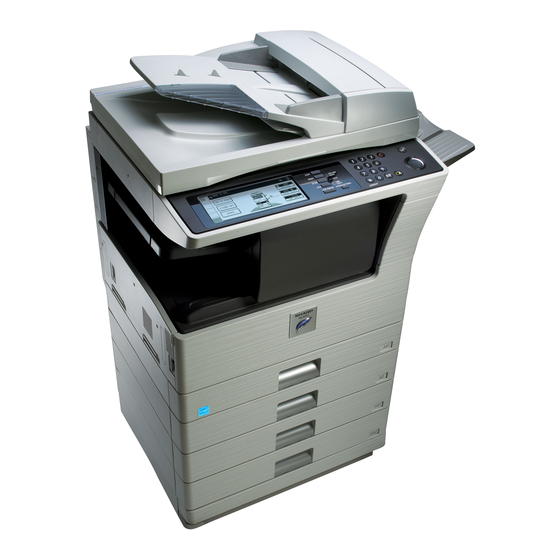
Sharp MX-M260 Service Manual
Digital multifunctional system
Hide thumbs
Also See for MX-M260:
- Software setup manual (172 pages) ,
- Operation manual (160 pages) ,
- Online manual (33 pages)
Table of Contents
Advertisement
Quick Links
[1] PRODUCT OUTLINE . . . . . . . . . . . . . . . . . . . . . . . . . . . . . . . . . . . 1-1
[2] SPECIFICATIONS . . . . . . . . . . . . . . . . . . . . . . . . . . . . . . . . . . . . . . 2-1
[3] CONSUMABLE PARTS . . . . . . . . . . . . . . . . . . . . . . . . . . . . . . . . . . 3-1
[4] EXTERNAL VIEW AND INTERNAL STRUCTURE . . . . . . . . . . . . . 4-1
[5] ADJUSTMENTS . . . . . . . . . . . . . . . . . . . . . . . . . . . . . . . . . . . . . . . 5-1
[6] SIMULATION . . . . . . . . . . . . . . . . . . . . . . . . . . . . . . . . . . . . . . . . . . 6-1
[7] SELF DIAG AND TROUBLE CODE . . . . . . . . . . . . . . . . . . . . . . . . 7-1
[8] MAINTENANCE. . . . . . . . . . . . . . . . . . . . . . . . . . . . . . . . . . . . . . . . 8-1
[9] FIRMWARE UPDATE . . . . . . . . . . . . . . . . . . . . . . . . . . . . . . . . . . . 9-1
[10] ELECTRICAL SECTION . . . . . . . . . . . . . . . . . . . . . . . . . . . . . . . . 10-1
Parts marked with "
" are important for maintaining the safety of the set. Be sure to replace these parts with
specified ones for maintaining the safety and performance of the set.
SERVICE MANUAL
DIGITAL MULTIFUNCTIONAL
SYSTEM
MX-M260/M310
MX-M260N/M310N
MODEL
CONTENTS
CODE: 00ZMXM310/S1E
This document has been published to be used
for after sales service only.
The contents are subject to change without notice.
Advertisement
Table of Contents

Subscribe to Our Youtube Channel
Related Manuals for Sharp MX-M260


Summary of Contents for Sharp MX-M260
-
Page 1: Service Manual
SERVICE MANUAL CODE: 00ZMXM310/S1E DIGITAL MULTIFUNCTIONAL SYSTEM MX-M260/M310 MX-M260N/M310N MODEL CONTENTS NOTE FOR SERVICING [1] PRODUCT OUTLINE ........1-1 [2] SPECIFICATIONS . -
Page 2: Table Of Contents
CONTENTS NOTE FOR SERVICING [5] ADJUSTMENTS 1. Warning for servicing ....... . i 1. -
Page 3: Note For Servicing
• Lightning conductor 8) The machine has got sharp edges inside. Be careful not to dam- age fingers when servicing. • A water pipe or a water faucet, which is not recognized as a grounding object by the authorities. -
Page 4: Note For Installing Site
5) When visually checking the inside of the machine for the operation check, be careful not to allow laser beams to enter the eyes. If the above precaution is neglected or an undesignated work is per- formed, safety may not be assured. MX-M260/M310/M260N/M310N NOTE FOR SERVICING - ii... -
Page 5: Line Of Machines And Options
[MX-PB12] [AR-FX7] [AR-SM6](512MB) [AR-MM9] Application integration Sharpdesk Network scanner Barcode font kit Flash ROM kit PS3 expantion kit module kit license kit expantion kit [MX-USX1/ MX-USX5/ MX-US10/ MX-US50/ [MX-AMX1] [MX-NSX1] [MX-PK10] [AR-PF1] [AR-PF2] MX-USA0] MX-M260/M310/M260N/M310N PRODUCT OUTLINE 1 - 1... -
Page 6: Combination Of Options List
MX-USX5 Sharpdesk 10 license kit MX-US10 Sharpdesk 50 license kit MX-US50 Sharpdesk 100 license kit MX-USA0 Application integration module kit MX-AMX1 Data security Data security kit (Commercial version) MX-FR17U For 26cpm MX-FR18U For 31cpm MX-M260/M310/M260N/M310N PRODUCT OUTLINE 1 - 2... -
Page 7: Basic Function
C. Operation panel Type Dot matrix LCD, touch panel Size Monochrome H-VGA 8.1” Display dot number 640 x 240 (H-VGA) LCD drive display area 192 x 72mm LCD backlight Fluorescent lamp backlight system LCD contrast adjustment MX-M260/M310/M260N/M310N SPECIFICATIONS 2 - 1... - Page 8 A3, B4, A4, A4R, A5 Mixed paper feed Enable (Same width only) Manual setting 11 x 17, 8.5 x 14, 8.5 x 13 (216 x 330), 8.5 x 11, 8.5 x 11R, A3, B4, A4, A4R, A5 MX-M260/M310/M260N/M310N SPECIFICATIONS 2 - 2...
- Page 9 Type and weight of 56 - 105g/m /15 - 21.3 lbs Bond paper which can be Duplex print from manual paper feed can be passed made. (Except for heavy paper, OHP sheet, and other special paper) MX-M260/M310/M260N/M310N SPECIFICATIONS 2 - 3...
- Page 10 Compression system • Non-compression • MH Server • G3 = MH • MR 2008 x64 • G4 = MMR • MMR 9.0 - 9.2.2 • JBIG X 10.2.8 X 10.3.9 X 10.4.11 X 10.5 - 10.5.6 MX-M260/M310/M260N/M310N SPECIFICATIONS 2 - 4...
- Page 11 8 items Direct address Input from the soft Input with 10 key, # key, ∗key input keyboard ✕ ❍ Chain dial (Supported by the pause key) ✕ Resend The latest single destination is called out. MX-M260/M310/M260N/M310N SPECIFICATIONS 2 - 5...
- Page 12 Empty capacity of 50MB or above Usage environmental Temperature 10 - 35°C Interface USB2.0 conditions Humidity 20 - 85%RH 10/100BASE-TX Atmospheric 590 - 1013 hPa Communication LPR/lp pressure (height: 0 - 2000m) protocol Port 9100 (RAW) MX-M260/M310/M260N/M310N SPECIFICATIONS 2 - 6...
-
Page 13: Supply System Table
Toner cartridge (With IC chip) ×1 MX-312FT Life setting by A4 (8.5"×11") 6% document (black) (Toner; Net 700g) Developer (black) Developer ×1 26cpm: 75K MX-312FV (Developer; Net 300g) 31cpm: 100K Drum Drum ×1 26cpm: 75K MX-312FR 31cpm: 100K MX-M260/M310/M260N/M310N CONSUMABLE PARTS 3 - 1... -
Page 14: Maintenance Parts List
3 times. (Supplied as a drum frame unit.) Transfer roller unit Transfer roller unit ×1 150K MX-311TX Staple cartridge Staple cartridge ×3 5000 staples ×3 MX-SCX1 ∗ The other maintenance parts than the above are supplied as service parts. MX-M260/M310/M260N/M310N CONSUMABLE PARTS 3 - 2... -
Page 15: Developer/Drum Life End Definition
C. STCL/ SRH/ SRS/ SRSSC/ SBI/ Agent (MX-M260/M310/M260N/M310N) Model Item Content Life Remarks name Upper heat roller kit Upper heat roller ×1 150K AR-310UH Fuser gear ×1 Upper heat roller bearing ×2 Upper cleaning pad ×1 Fusing separation pawl (upper) ×4... -
Page 16: Production Number Identification
Indicates the production month. manufactured month (Production lot) 5, 6 Number under unsealed state Indicates the production day. Drum: 36 months from the manufactured month under unsealed state Hyphen Number Indicates the production lot. MX-M260/M310/M260N/M310N CONSUMABLE PARTS 3 - 4... -
Page 17: External View
Regular paper and special paper (such as transparency film) can be fed from the bypass tray. Bypass tray extension Pull out the bypass tray extension before placing paper in the bypass tray. MX-M260/M310/M260N/M310N EXTERNAL VIEW AND INTERNAL STRUCTURE 4 - 1... -
Page 18: Internal Structure
Do not touch the fusing unit when removing misfed paper. Doing so may cause a burn or injury. Fusing unit paper guide Open to remove misfed paper. MX-M260/M310/M260N/M310N EXTERNAL VIEW AND INTERNAL STRUCTURE 4 - 2... -
Page 19: Operation Panel
This key blinks when auto power shut mode has activated. Press the key to return to normal operation. [INTERRUPT] key ( Use to perform an interrupt copy job. MX-M260/M310/M260N/M310N EXTERNAL VIEW AND INTERNAL STRUCTURE 4 - 3... -
Page 20: Rspf
Document length detection SW (Long) Photo transmission Detects the document length on the tray. OPCLS Book sensor Photo transmission Detects the SPF float. Paper exit sensor Photo transmission Detects presence of documents. Document width sensor Volume Detects the document width on the tray. MX-M260/M310/M260N/M310N EXTERNAL VIEW AND INTERNAL STRUCTURE 4 - 4... -
Page 21: Sensor
Manual feed length MPLD2 Manual feed paper length detection sensor 2 detection Manual feed paper MPED Manual feed paper empty empty sensor detection 2nd tray paper pass PFD2 2nd tray paper pass sensor MX-M260/M310/M260N/M310N EXTERNAL VIEW AND INTERNAL STRUCTURE 4 - 5... -
Page 22: Drive Motor
Solenoid for the paper feed Toner motor Toner supply solenoid from the tray Paper feed solenoid CPFC1 Solenoid for the paper feed from the tray Separation pawl PSPS Separation pawl operation solenoid solenoid MX-M260/M310/M260N/M310N EXTERNAL VIEW AND INTERNAL STRUCTURE 4 - 6... -
Page 23: Lamp
Intake fan motor DCFM2 Fusing paper exit fan VFM2 Cools the inside of the unit. (31 sheet model) Fusing paper exit fan VFM2 Cools the inside of the unit. Ozon filter Ozon filter MX-M260/M310/M260N/M310N EXTERNAL VIEW AND INTERNAL STRUCTURE 4 - 7... -
Page 24: Roller
Transports the picked up paper to RESIST section. 2nd tray pick-up roller Picks up paper from the tray. 2nd tray paper feed roller Transports the picked up paper to RESIST section. MX-M260/M310/M260N/M310N EXTERNAL VIEW AND INTERNAL STRUCTURE 4 - 8... -
Page 25: Adjustment Item List
∗ When inserting a thickness gauge, be careful not to scratch the developing doctor and the MG roller. <Adjustment specification> Developing doctor gap +0.1mm F/C/R: 1.5 -0.15mm MX-M260/M310/M260N/M310N ADJUSTMENTS 5 - 1... - Page 26 TEXT (122) (122mm/s) Enter the adjustment value with the 10-key. TEXT/PHOTO Character/Photo 5) Press the [START] key. (122) (122mm/s) Copying is started. PHOTO (122) Photo (122mm/s) TONER SAVE Toner save (122) (122mm/s) Min. unit: –10V increment MX-M260/M310/M260N/M310N ADJUSTMENTS 5 - 2...
- Page 27 5) Enter the set value and press the start key. The correction value is stored and a copy is made. <Adjustment specification> Adjustment Spec Setting Set value mode value range Rear edge 1 step: 0.127mm 4mm or 1 – 99 50-1-6 void shift less MX-M260/M310/M260N/M310N ADJUSTMENTS 5 - 3...
- Page 28 Image loss amount adjustment (Lead edge image loss set value) (OC) <Adjustment specification> Adjustment Spec Setting Set value mode value range Left edge void 50-1 1 step: 0.127mm 0.5 – 4mm 1 – 99 shift MX-M260/M310/M260N/M310N ADJUSTMENTS 5 - 4...
- Page 29 • When a copy as shown is made. Paper exit direction Original Copy 4) Loosen the set screw of the scanner drive pulley which is not in contact with No. 2/3 mirror base unit positioning plate. MX-M260/M310/M260N/M310N ADJUSTMENTS 5 - 5...
- Page 30 Paper exit Rear side direction When La = Lb and Lc = Ld, no need to perform the procedures 4) Front side and 5). 5) Tighten the fixing screw of the mirror base drive pulley. MX-M260/M310/M260N/M310N ADJUSTMENTS 5 - 6...
- Page 31 The current front surface sub scanning direction magnification ratio Enter the set value and press the start key. correction value is displayed in two digits on the display section. The correction value is stored and a copy is made. MX-M260/M310/M260N/M310N ADJUSTMENTS 5 - 7...
- Page 32 3) Slide the lens unit toward the rear side and attach it, then execute SIM. ∗ When the lens unit is moved, execute the OC main scanning magni- fication ratio auto adjustment, SIM 48-1-1. ∗ This adjustment is basically O.K. with SIM 63-7. MX-M260/M310/M260N/M310N ADJUSTMENTS 5 - 8...
- Page 33 If too dark, AE (TONER 0 – 99 – "3" is copied. SAVE) decrease the quantity displayed TEXT (TONER "3" is copied. SAVE) on the copy quantity display. TEXT PHOTO "3" is copied. (TONER SAVE) MX-M260/M310/M260N/M310N ADJUSTMENTS 5 - 9...
-
Page 34: Simulation
50-12, 51-2, the bold-faced items in the above list.) * If the entry value is outside the adjustable range, an error buzzer sounds and the adjustment value is not renewed. Page shift is not made, either. MX-M260/M310/M260N/M310N SIMULATION 6 - 1... - Page 35 (Other modes) The display is made according to the selected mode and the item. Do you want to change the content ? Enter the new setting and adjustment values. MX-M260/M310/M260N/M310N SIMULATION 6 - 2...
-
Page 36: Simulation Code List
Used to make the initial setting of toner rotation to reverse rotation or from reverse rotation concentration when replacing developer. to normal rotation of the duplex motor. Used to check the operation of the toner motor and its control circuit. MX-M260/M310/M260N/M310N SIMULATION 6 - 3... - Page 37 The sensor of an uninstalled tray is not displayed. Used to set the AE and the limit value in AE (Toner save). Used to set the AE and the limit value in AE (Toner save). Used to switch the FAX send image quality. MX-M260/M310/M260N/M310N SIMULATION 6 - 4...
- Page 38 (auto print operation). Used to adjust the touch panel (LCD display section) detection position. Used to check the touch panel (LCD display section) detection position adjustment result. Used to check the key inputs of the operation panel. MX-M260/M310/M260N/M310N SIMULATION 6 - 5...
-
Page 39: Details Of Simulation
Set magnification ratio (Default 100%) Document size Varies depending on the destination. Duplex Selectable only when RSPF is installed. Set number of times 1 to 999 (0: Continuous operation) Note: Executable only when the RSPF is installed. MX-M260/M310/M260N/M310N SIMULATION 6 - 6... - Page 40 Paper alignment motor R FPAM-F Paper alignment motor F FPDM Paper delivery motor Paddle solenoid FPTM Paper transport motor FDRLM Delivery roller lift motor FPGS Paper gate solenoid FARLS Alignment roller lift solenoid Staple light MX-M260/M310/M260N/M310N SIMULATION 6 - 7...
- Page 41 4th tray pick-up solenoid Item Operation CPFS4 4th tray paper feed clutch Operation/procedure Note: Execution is possible only when the option tray is installed. When the [START] key is pressed, the copy lamp is lighted for 10sec. MX-M260/M310/M260N/M310N SIMULATION 6 - 8...
- Page 42 This setting is valid when SIM 7-1 (Intermittent setting) is enabled. DCFM&DCFM2 operations Setting range 1-255 VFM2 Fusing exit paper fan operates Default Fusing fan, power cooling fan, and VFM&DCFM&DCFM2 power cooling fan 2 are operated at the &VFM2 same time. MX-M260/M310/M260N/M310N SIMULATION 6 - 9...
- Page 43 The minimum increment is 10V. The result of (Set value) -200/ 10 is stored in the EEPROM. When reading a value from the EEPROM, the value of (EEP value *10+200) is used as the set value. MX-M260/M310/M260N/M310N SIMULATION 6 - 10...
- Page 44 Min. unit: 10V increment Item Content Duplex motor/Duplex 2 motor forward rotation DMF145 (145mm/s) Duplex motor/Duplex 2 motor forward rotation DMF122 (122mm/s) Duplex motor/Duplex 2 motor reverse rotation DMR145 (145mm/s) Duplex motor/Duplex 2 motor reverse rotation DMR122 (122mm/s) MX-M260/M310/M260N/M310N SIMULATION 6 - 11...
- Page 45 Operation/procedure replaced part's counter only. 1. Press the [START] key. 2. When “1: YES” is selected, troubles other than U2 and PF are can- celed. (When “2: NO” is selected, the simulation is canceled.) MX-M260/M310/M260N/M310N SIMULATION 6 - 12...
- Page 46 If it is not installed, “- - - - - - - - - -” is displayed. section may be determined by the data. Panel (Jam cause code) Destination Panel software support language display Item Jam contents Japan Japanese, American English, English TRAY1 1st tray pick-up miss MX-M260/M310/M260N/M310N SIMULATION 6 - 13...
- Page 47 NONE/[10: FAX] FAX MEM NONE/Memory capacity (MB) Note: When the simulation is canceled, the display returns to the origi- HAND SET NONE/[11: Handset] nal state but the machine is not reset. USB HOST NONE/USB HOST MX-M260/M310/M260N/M310N SIMULATION 6 - 14...
- Page 48 SPF P-IN JAM_REV (Paper after JAM counter/JAM history reverse jam sensor reversing) SPF JAM RSPF JAM counter/RSPF JAM history RSPF short size SPF P-IN Passed (OFF at TROUBLE Trouble counter/Trouble history ORG_SHORT error sensor JAM) MX-M260/M310/M260N/M310N SIMULATION 6 - 15...
- Page 49 2. Press the [START] key. The confirmation menu is shown. 3. Select “1: YES.” 1: YES (Cleared) 2: NO (Not cleared) (Default) Item Content PRINTER Printer counter IMC counter DUPLEX DUPLEX counter OTHERS The other counters MX-M260/M310/M260N/M310N SIMULATION 6 - 16...
- Page 50 A4 as Letter in the AB series. 2:A4<->LT open) after turning on the power, this simulation can be performed. 0: Detection disable (Default) 1: Detection valid 8.5” x 13” detection valid/invalid setup Set value Setup Remarks Detection invalid Default Detection valid MX-M260/M310/M260N/M310N SIMULATION 6 - 17...
- Page 51 Section Auditor INEG EX inch series 0-14 Item Specifications ABEG EX AB series INEF EX inch series (FC) ABEF EX AB series (FC) CHINESE China TAIWAN Taiwan AB SEEG2 SEEG2 TAIWAN2 Taiwan China MX-M260/M310/M260N/M310N SIMULATION 6 - 18...
- Page 52 20 TAIWANESE Traditional Chinese supported locally Function Used to input the Software Key for the PS extention kit. 21 SLOVAK (Purpose) 22 HEBREW Supported locally Section Printer BRAZILIAN Item Specifications PORTUGUESE 24 ARABIC 25 FARSI MX-M260/M310/M260N/M310N SIMULATION 6 - 19...
- Page 53 Operation/procedure Disable (Error Beep) Enter the set value with the 10-key, and press the [START] key. This setup varies in connection with SIM 26-6 (Destination setup). Item Content Default Enable 1 (U.K.) 0 (Others) Disable MX-M260/M310/M260N/M310N SIMULATION 6 - 20...
- Page 54 Retry number setting of initial Input the set value with the 10-key and press the [START] key. 0-15 RETRY connection (unit: times) Setting Item Content Default range Letterhead paper is not set. Letterhead paper is set. MX-M260/M310/M260N/M310N SIMULATION 6 - 21...
- Page 55 Manual feed paper length detection 1 MPLD2 Manual feed paper length detection 2 Width detection size of the manual feed tray (one of them is displayed.) A4/A3, LT/WLT, B5/B4, INV/LTR, A5/A4R, B5R, POSTCARD, EXTRA, 8K/16K (At detection, highlighted) MX-M260/M310/M260N/M310N SIMULATION 6 - 22...
- Page 56 (Hexadecimal display) For AB series, 1 to 5 is displayed, for inch series, 1 to 4. 41-4 Purpose Adjustment Function Used to adjust the detection level of OC 20 degrees. (Purpose) Section Others Item Operation MX-M260/M310/M260N/M310N SIMULATION 6 - 23...
- Page 57 (145) temperature Sub Function Used to make various setups in each mode of process (145mm/s) (Purpose) control. WarmUp Warmup Image process Section Temp Main complete (Photoconductor/Developing/Transfer/Cleaning) 0 - 40 (122) temperature Main Item Operation (122mm/s) MX-M260/M310/M260N/M310N SIMULATION 6 - 24...
- Page 58 Item Operation 5143876 - 6001188 (26-sheet model) 1-99 Operation/procedure 6001189 - 6858500 (26-sheet model) 1-99 Used to display the process control correction information. 6858501 - 7715813 (26-sheet model) 1-99 7715814 - 8573125 (26-sheet model) 1-99 MX-M260/M310/M260N/M310N SIMULATION 6 - 25...
- Page 59 37 +V1S-F (122) +V1 single surface. Duplex 5-30 +V2 Duplex (Back) (Front) 145mm/s normal paper N1 122mm/s normal paper N1 5 +V1S-F (145) +V1 single surface. Duplex 5-30 38 +V1S-R (122) 5-30 +V1 Duplex (Back) (Front) MX-M260/M310/M260N/M310N SIMULATION 6 - 26...
- Page 60 Character level 5.0 (slant) 1-99 Default 4 (sec) TS 1.0 Character (TS) level 1.0 1-99 (SHIFT) (shift q’ty) 1TS 1.0 Character (TS) level 1.0 1-99 (GAMMA) (slant) TS 2.0 Character (TS) level 2.0 1-99 (SHIFT) (shift q’ty) MX-M260/M310/M260N/M310N SIMULATION 6 - 27...
- Page 61 TS 2.0 Character/Photo (TS) level 2.0 DOOR OPEN 1-99 (SHIFT) (shift q’ty) Error display TS 2.0 Character/Photo (TS) level 2.0 PAPER EMPTY 1-99 (GAMMA) (slant) TS 3.0 Character/Photo (TS) level 3.0 1-99 (SHIFT) (shift q’ty) MX-M260/M310/M260N/M310N SIMULATION 6 - 28...
- Page 62 Fine text MANUAL 0-99 MANUAL (PHOTO ON) (Half tone) Ultra Fine MANUAL (PHOTO OFF) MANUAL Fine text MANUAL (PHOTO OFF) Note: Executable only when the FAX is installed. Note: Executable only when the FAX is installed. MX-M260/M310/M260N/M310N SIMULATION 6 - 29...
- Page 63 Japan to EX Japan, the set value becomes 2 (Default: EX Japan) • If the auto exposure mode setup value is changed, the setup value of SIM 46-30 (AE limit setup) is reset to the default value. MX-M260/M310/M260N/M310N SIMULATION 6 - 30...
- Page 64 RSPF back surface sub scan SCAN Sub scanning SPF (SIDE2) magnification ratio SPF(SUB) magnification ratio 1-255* adjustment (SPF) SCAN Main scanning RSPF(MAIN) magnification ratio 1-255* adjustment (RSPF) SCAN Sub scanning RSPF(SUB) magnification ratio 1-255* adjustment (RSPF) MX-M260/M310/M260N/M310N SIMULATION 6 - 31...
- Page 65 Note: When this simulation is canceled, the display is shifted to the ini- When the [START] key is pressed, the display goes to the copying tial menu, but the machine is not reset. state and print is started. (When the [P] key is pressed: Copy menu) MX-M260/M310/M260N/M310N SIMULATION 6 - 32...
- Page 66 (Back surface) Normal display NOW PRINTING DOOR OPEN Note: Executable only when the FAX is installed. Error display PAPER EMPTY There is no tray selection operation. The optimum paper tray for the scanned size is selected. MX-M260/M310/M260N/M310N SIMULATION 6 - 33...
- Page 67 Used to set the OPC drum separation pawl operation surface scan 1-99 (Purpose) inhibit. (ON/OFF) RSPF document back SPF(SIDE2) Image process surface scan Section (Photoconductor/Developing/Transfer/Cleaning) Item Operation Operation/procedure Select the set value with the 10-key. Item Content Setting range Default Enable Disable MX-M260/M310/M260N/M310N SIMULATION 6 - 34...
- Page 68 2. Enter the RSPF original tray size adjustment value (specified on The bit to be changed is specified by 10-key. (The current value is high- the back of the RSPF) with the 10-key. lighted.) When [START] key is pressed, the entered value is set. MX-M260/M310/M260N/M310N SIMULATION 6 - 35...
- Page 69 After completion of all key entries, “COMPLETE” is displayed. Section Printer Item Operation Operation/procedure 1. Select the print item with the 10-key. 2. Press the [START] key. The display is shifted to the copy menu. MX-M260/M310/M260N/M310N SIMULATION 6 - 36...
- Page 70 19.2 V34 Note: Executable only when the FAX is installed. 9 16.8 V34 16.8 V34 10 14.4 V34 14.4 V34 11 12.0 V34 12.0 V34 12 9.6 V34 9.6 V34 13 7.2 V34 7.2 V34 MX-M260/M310/M260N/M310N SIMULATION 6 - 37...
- Page 71 14.4 V34 Note: Executable only when the FAX is installed. 11 12.0 V34 12.0 V34 12 9.6 V34 9.6 V34 13 7.2 V34 7.2 V34 14 4.8 V34 4.8 V34 15 2.4 V34 2.4 V34 MX-M260/M310/M260N/M310N SIMULATION 6 - 38...
- Page 72 Item NO SIGNAL Setting Item Content 11111 range 11110 EXECUTE Execution – 00000 HIGH (SW) High group 0-15 010101 HIGH-LOW (SW) High group, Low group 0-15 00001 Note: Executable only when the FAX is installed. MX-M260/M310/M260N/M310N SIMULATION 6 - 39...
- Page 73 * The AR-FX5 data cannot be written into the AR-FX7. If it is exe- cuted, data are initialized and deleted. In addition, the AR-FX7 data cannot be used in the AR-FX5. Note: Executable only when the FAX is installed. MX-M260/M310/M260N/M310N SIMULATION 6 - 40...
- Page 74 SW. Signal detection and delivery of pseudo-call sound at detection are executed until the interruption command is provided by pressing the [SYSTEM SETTINGS] key. Note: Executable only when the FAX is installed. MX-M260/M310/M260N/M310N SIMULATION 6 - 41...
- Page 75 * In the other case than the serviceman call error, entering the simula- tion is inhibited during the system check operation is displayed. After completion, the result is displayed. Note: Executable only when the PCL is installed. MX-M260/M310/M260N/M310N SIMULATION 6 - 42...
- Page 76 * In the other case than the serviceman call error, entering the simula- tion is inhibited during the system check operation is displayed. Note: Executable only when PCL and NIC are installed. MX-M260/M310/M260N/M310N SIMULATION 6 - 43...
-
Page 77: Trouble Code List
FAX control PWB communication trouble (Overrun) FAX control PWB communication trouble (Framing) FAX control PWB communication trouble (Time-out) Combination error between the MCU and the FAX firmware. FAX control PWB destination error MX-M260/M310/M260N/M310N SELF DIAG AND TROUBLE CODE 7 - 1... -
Page 78: Details Of Trouble Code
CODEC IC (JBIG chip) abnormality on MCU PWB. IMC PWB remedy Check the grounding of the copier. Cause IMC PWB abnormality Check the ROM of the IMC PWB. Check Replace the IMC PWB remedy MX-M260/M310/M260N/M310N SELF DIAG AND TROUBLE CODE 7 - 2... - Page 79 Overcurrent to the motor. Check laser LED lighting. Finisher control PWB trouble. Replace the LSU unit. Check Use SIM3-3 to check the paddle motor Replace the MCU PWB. operation remedy MX-M260/M310/M260N/M310N SELF DIAG AND TROUBLE CODE 7 - 3...
- Page 80 Check the connection of temperature humidity sensor. Details An improper option is installed. remedy Replace the temperature humidity sensor. Cause Configuration of the paper exit option is improperness. Check Install a proper option. remedy MX-M260/M310/M260N/M310N SELF DIAG AND TROUBLE CODE 7 - 4...
- Page 81 Check the variety of FAX LIU PWB. Check the grounding of the copier. Check the machine destination setup (Sim Check FAX control PWB ROM. remedy 22-6) and FAX country code (Soft SW table). MX-M260/M310/M260N/M310N SELF DIAG AND TROUBLE CODE 7 - 5...
- Page 82 Printer PWB ROM defect/Data failure. Check Check the connectors and the harness of the printer PWB and MCU PWB. remedy Check the grounding of the copier. Check ROM on printer PWB. MX-M260/M310/M260N/M310N SELF DIAG AND TROUBLE CODE 7 - 6...
- Page 83 Check for disconnection of the heater lamp and thermostat. Check the interlock switch. Check the power circuit and the lamp control circuit on MCU PWB. Clear the display of self-diagnostics with SIM 14. MX-M260/M310/M260N/M310N SELF DIAG AND TROUBLE CODE 7 - 7...
- Page 84 Check the POD1, POD2 or PPD2 sensor. SIM 14. Clear the trouble with SIM 14. Check that there is no foreign material in the contact section between the thermistor and the heat roller. MX-M260/M310/M260N/M310N SELF DIAG AND TROUBLE CODE 7 - 8...
- Page 85 Check Check the polygon motor operation with SIM 61-1. Replace the MCU PWB. remedy Check the connectors and the harness of polygon motor Replace the polygon motor. Replace the MCU PWB. MX-M260/M310/M260N/M310N SELF DIAG AND TROUBLE CODE 7 - 9...
- Page 86 MCU. (Use the operation control PWB and MCU PWB. remedy SIM 26-6 for the destination of the body.) remedy Check the grounding of the copier. Check ROM on the operation control PWB. MX-M260/M310/M260N/M310N SELF DIAG AND TROUBLE CODE 7 - 10...
- Page 87 Use SIM 25-2 to perform the auto developer adjustment. remedy Content PF trouble Details The copy inhibit command from RIC is received. Cause Judged by the host. Check Inform to the host. remedy MX-M260/M310/M260N/M310N SELF DIAG AND TROUBLE CODE 7 - 11...
-
Page 88: Maintenance
– – – – ❍ ❍ ❍ ❍ ❍ ❍ ❍ ❍ Others Paper feed rollers ✩ ✩ ✩ ✩ ✩ ✩ ✩ ✩ Gears ▲ ▲ ▲ ▲ ▲ ▲ ▲ ▲ Ozone filter MX-M260/M310/M260N/M310N MAINTENANCE 8 - 1... - Page 89 – – – – ❍ ❍ ❍ ❍ ❍ ❍ ❍ ❍ Others Paper feed rollers ✩ ✩ ✩ ✩ ✩ ✩ ✩ ✩ Gears ▲ ▲ ▲ ▲ ▲ ▲ ▲ ▲ Ozone filter MX-M260/M310/M260N/M310N MAINTENANCE 8 - 2...
-
Page 90: Details Of Maintenance
(2) Exit roller H. Laser unit (1) LSU I. Power unit (1) Power source J. PWB (1) Option CN PWB (2) IMC PWB (3) MCU PWB (4) Motherboard PWB (5) Second interface PWB K. Ozone filter MX-M260/M310/M260N/M310N MAINTENANCE 8 - 3... - Page 91 Note: When installing the process unit in the main unit after replacing the drum, process unit may not be able to install by reason of the drum drive coupling position. In this case, rotate the drum about 45 degrees and install again. MX-M260/M310/M260N/M310N MAINTENANCE 8 - 4...
- Page 92 Note: If it disturbs the blade movement, replace it and attach new one. e. Separation pawl Disassembly* Hold the tip of the separation pawl and remove it. Assembly* Press the center of the separation pawl and install it. MX-M260/M310/M260N/M310N MAINTENANCE 8 - 5...
- Page 93 • Clean the sensor only after removing used DV when replacing DV. [DV side sheet F/ DV side sheet R attachment reference] C. Fusing section Molt Molt edge edge reference reference Projection edge Projection edge reference reference MX-M260/M310/M260N/M310N MAINTENANCE 8 - 6...
- Page 94 (3) Paper guide (1) Thermostat Note: When securing the lamp harness and the thermostat, the tightening torque of the screw (4 positions) is 6-9 kgs. (4) Fusing separation pawl (lower) (5) Lower heat roller (2) Thermistor MX-M260/M310/M260N/M310N MAINTENANCE 8 - 7...
- Page 95 (8) Fusing separation pawl (upper) (9) Upper heat roller (6) Heater lamp (7) Upper cleaning pad (10) Thermistor cleaning pad MX-M260/M310/M260N/M310N MAINTENANCE 8 - 8...
- Page 96 D. Optical section (1) CCD unit a. Lamp (2) Lamp unit b. PWB MX-M260/M310/M260N/M310N MAINTENANCE 8 - 9...
- Page 97 (1) Paper feed solenoid (2) Tray sensor PWB (3) Manual P-in sensor/Manual empty sensor d. Mirror motor (4) Multi manual paper feed a. Paper feed roller/pickup roller E. Paper feed section Paper feed roller Pickup roller Separation sheet MX-M260/M310/M260N/M310N MAINTENANCE 8 - 10...
- Page 98 ∗ Slightly apply grease GP501MR (UKOG-0012QSZZ) around the axis. One rice grain for each. Installation*Install so that the cam transmit arm (1) comes under the d. Clutch/solenoid roller arm (2). (Clutch) b. Reverse sensor (Solenoid) MX-M260/M310/M260N/M310N MAINTENANCE 8 - 11...
- Page 99 (Clutch) (5) Upper 500 sheets tray paper feed a. Paper feed roller/pickup roller Note: With the toner cartridge installed, do not tilt or shake the devel- oper cartridge. MX-M260/M310/M260N/M310N MAINTENANCE 8 - 12...
- Page 100 Separation sheet ∗ When replacing, be careful not Slightly apply grease GE676 to adhere conduction grease (UKOG-0013QSZZ) to the (black) to the drive section. drum boss. MX-M260/M310/M260N/M310N MAINTENANCE 8 - 13...
- Page 101 Grease should not come out when assembling. (6) Lower 500 sheets tray paper feed a. Paper feed roller/pickup roller ∗ Slightly apply grease GP501MR (UKOG-0012QSZZ) around the axis. One rice grain for each. Grease should not come out when assembling. MX-M260/M310/M260N/M310N MAINTENANCE 8 - 14...
- Page 102 Transport clutch g. Solenoid e. Paper feed clutch h. Sensor PWB f. Transport clutch F. Side door unit (1) Transport roller unit ∗ Check that two springs are securely inserted into the transfer roller unit bosses. MX-M260/M310/M260N/M310N MAINTENANCE 8 - 15...
- Page 103 (2) Transport roller (4) DUP motor (3) DUP transport roller G. 1st paper exit unit (1) Cooling fan MX-M260/M310/M260N/M310N MAINTENANCE 8 - 16...
- Page 104 (2) Exit roller (Except North America) MX-M260/M310/M260N/M310N MAINTENANCE 8 - 17...
- Page 105 2) Remove the left cabinet and exit tray. 3) Disconnect the LSU connector, and remove the securing screws to remove the LSU. Note: Check to confirm that the solenoid shaft is in the gate bracket, and fix with the screw. MX-M260/M310/M260N/M310N MAINTENANCE 8 - 18...
- Page 106 I. Power unit (1) Power source J. PWB (1) Option CN PWB MX-M260/M310/M260N/M310N MAINTENANCE 8 - 19...
- Page 107 (2) IMC PWB (4) Motherboard PWB (3) MCU PWB MX-M260/M310/M260N/M310N MAINTENANCE 8 - 20...
- Page 108 (5) Second interface PWB K. Ozone filter MX-M260/M310/M260N/M310N MAINTENANCE 8 - 21...
- Page 109 Note: Before removing the left cover, remove the No.1 tray in advance. (3) Toner motor (4) PS transport clutch L. Drive section (1) DUP reverse motor (2) Main drive motor MX-M260/M310/M260N/M310N MAINTENANCE 8 - 22...
- Page 110 (5) Paper feed clutch (7) Lift up motor (6) Drive unit M. Transport section Drive unit (Grease application part) (1) Transport roller MX-M260/M310/M260N/M310N MAINTENANCE 8 - 23...
- Page 111 (2) OPU PWB (3) Key PWB N. Operation section (1) Operation section MX-M260/M310/M260N/M310N MAINTENANCE 8 - 24...
- Page 112 (4) LCD unit P. RSPF (1) Document tray section a. Document tray unit O. Switch (1) Power switch MX-M260/M310/M260N/M310N MAINTENANCE 8 - 25...
- Page 113 Document length sensor (2) Paper feed unit section a. Paper feed clutch b. Pickup roller c. Document width resistor PWB MX-M260/M310/M260N/M310N MAINTENANCE 8 - 26...
- Page 114 Paper feed roller d. Paper feed unit e. Separation sheet MX-M260/M310/M260N/M310N MAINTENANCE 8 - 27...
- Page 115 Sensor b. PS clutch c. Pressure release solenoid (3) Transport section a. Transport unit d. RSPF motor MX-M260/M310/M260N/M310N MAINTENANCE 8 - 28...
- Page 116 Roller <Note for disassembling the motor> The motor is positioned by the jig. Use the mark when assembling it to the original position. e. Transport roller g. Sensor MX-M260/M310/M260N/M310N MAINTENANCE 8 - 29...
- Page 117 Roller (4) Base section a. Interface PWB b. Solenoid i. Roller c. Book sensor MX-M260/M310/M260N/M310N MAINTENANCE 8 - 30...
-
Page 118: Other Related Items
FAX counter clear SIM 24-10 Scanner mode counter clear SIM 24-15 ∗ 31 sheet model: When maintenance message is displayed, replace consumption part reaching the number of sheets of maintenance, then clear the replaced part's counter only. MX-M260/M310/M260N/M310N MAINTENANCE 8 - 31... -
Page 119: Firmware Update Procedure
Prepare following files necessary for program update • Maintenance software: maintenance.exe • Andromeda module file: ProcModelP.mdl • USB communication program: JGRtoPRN.exe • Maintenance tool driver: SFZEJENU.inf Ready to start download process when these trees appear. MX-M260/M310/M260N/M310N FIRMWARE UPDATE 9 - 1... - Page 120 12) Notice message "Download is complete. Check the copier panel to make sure the download is complete." will appear on PC. 13) Close maintenance program, and reset the machine by pressing CA key. This is the end of the download procedure. MX-M260/M310/M260N/M310N FIRMWARE UPDATE 9 - 2...
- Page 121 Restart maintenance program after confirming the selected download file is not abnormal and not using other application. An error. [0xXXXXXXXX] The error occurred except the above errors. [TROUBLESHOOTING] Restart maintenance program after confirming communication device of PC(either COM or parallel) is under right condition. MX-M260/M310/M260N/M310N FIRMWARE UPDATE 9 - 3...
-
Page 122: Block Diagram
CN29 CN12 CN31 CN501 CN30 CN502 CN18 CN27 CN23 (AB / INCH ) CN28 CN25 CN19 CN26 Paper Full Sensor 2nd POUT COVER SENSOR Pout 2 Ssensor CN14 Pout Gate CN22 Solenoid CN32 CN38 MX-M260/M310/M260N/M310N ELECTRICAL SECTION 10 - 1... - Page 123 (Option) slot2 8MB Flash SO-DIMM (Code) slot1 16MB MEMD[31:16] Flash SO-DIMM (Boot,ESC/P) slot0 4MB or 8MB MEMD[15:0] MEMD[31:0] MEMD[31:0] MEMD[31:0] LCX245 LCX244 LCX373 G-Bus IM-Bus UART Ch0 UART Ch1 PCI Connector PCI Connector Connector MX-M260/M310/M260N/M310N ELECTRICAL SECTION 10 - 2...
-
Page 124: Actual Wiring Chart
/INCHJP DGND LED0# DSIN2A 292250-8 DGND DSCLK# LED0# DSIN2B DGND OC COVER SENSOR DSCLK# OC COVER DGND LED0# PULL UP OCCOVER 292250-3 DGND 5V(PULL UP) MHP SENSOR 5V(PULL UP) PULL UP DGND DGND S3B-PH-K-S MX-M260/M310/M260N/M310N ELECTRICAL SECTION 10 - 3... -
Page 125: Mcu Pwb
B. MCU - Optical base plate 2, OP I/F PWB, 1st paper exit unit, 2nd paper exit unit (P2) MCU PWB CCD PWB OP I/F PWB RSPF (To P12) FINISHER RIC / DOWNLOAD/ PCI MX-M260/M310/M260N/M310N ELECTRICAL SECTION 10 - 4... - Page 126 C. Manual feed, 1st tray unit section (P3) [1st TRAY UNIT] MCU PWB MX-M260/M310/M260N/M310N ELECTRICAL SECTION 10 - 5...
- Page 127 <PAPER EMPTY SENSOR> <PAPER UPPER LIMIT SENSOR> SMR-02V-N SMP-02V-NC /PCS2 <PAPER FEED SL> CN7(B3B-PH-K-E) Blue 292250-2 CSS2 CSS2 <TRAY SENSOR SW> DGND DGND CN1(B3B-PH-K-R) Red B 3B-PH-K-S LUM2D LUM2D [LIFT UP MOTOR UNIT] PGND PGND MX-M260/M310/M260N/M310N ELECTRICAL SECTION 10 - 6...
- Page 128 E. Fusing unit, Power supply unit section (P5) HV PWB HARNESS GUIDE MCU PWB DGND RTH2 DGND RTH1 PDPX DGND 5V(PullUp) MX-M260/M310/M260N/M310N ELECTRICAL SECTION 10 - 7...
- Page 129 F. DV & LSU unit section (P6) MCU PWB MX-M260/M310/M260N/M310N ELECTRICAL SECTION 10 - 8...
- Page 130 GDATA3 GDATA3 GDATA3 GDATA5 GDATA5 GDATA5 GDATA7 GDATA7 GDATA7 GDATA9 GDATA9 GDATA9 GDATA11 GDATA11 GDATA11 GDATA13 GDATA13 GDATA13 GDATA15 GDATA15 GDATA15 /PCLREQ1P /FAXREQ1P /FAXREQ1P CN9(B3B-PH-K-S) /PCLCS1P /FAXCS1P /FAXCS1P /PCLREQ0P /FAXREQ0P /FAXREQ0P /PCLCS0P /FAXCS0P /FAXCS0P MX-M260/M310/M260N/M310N ELECTRICAL SECTION 10 - 9...
- Page 131 TRDY_ TRDY_ STOP_ STOP_ PERR_ PERR_ +3.3V +3.3V +3.3V +3.3V +3.3V +3.3V +3.3V +3.3V C/BE1 C/BE1 PCIAD15 PCIAD15 PCIAD13 PCIAD13 PCIAD11 PCIAD11 PCIAD9 PCIAD9 C/BE0 C/BE0 PCIAD7 PCIAD7 PCIAD5 PCIAD5 PCIAD3 PCIAD3 PCIAD1 PCIAD1 MX-M260/M310/M260N/M310N ELECTRICAL SECTION 10 - 10...
-
Page 132: Signal List
LUD4 Lift-up motor upper limit Detects the upper limit of Detected Option tray detection (Tray 4) the lift-up motor. detected LUM1H Lift-up motor Drives the lift plate of the CN15 paper tray. MX-M260/M310/M260N/M310N ELECTRICAL SECTION 10 - 11... - Page 133 Cools the fusing unit. CN504 POUTFANRDY Paper exit cooling fan lock Detects lock of the paper Rotation Lock CN504 detection exit cooling fan. PPD2 Paper pass sensor (Tray 2) Detects paper pass. Standard tray I/F MX-M260/M310/M260N/M310N ELECTRICAL SECTION 10 - 12...
- Page 134 TRCL2 Vertical transport clutch Controls ON/OFF of the Standard vertical transport roller. tray I/F TRCL3 Vertical transport clutch Controls ON/OFF of the Option tray vertical transport clutch. Paper empty sensor Detects paper empty. interface MX-M260/M310/M260N/M310N ELECTRICAL SECTION 10 - 13...
- Page 137 COPYRIGHT 2009 BY SHARP CORPORATION All rights reserved. Printed in Japan. No part of this publication may be reproduced, stored in a retrieval system, or transmitted, in any form or by any means, electronic; mechanical; photocopying; recording or otherwise without prior written permission of the publisher.
Need help?
Do you have a question about the MX-M260 and is the answer not in the manual?
Questions and answers