Table of Contents
Advertisement
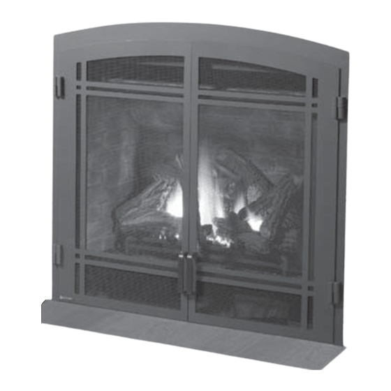
Regency Bellavista
WARNING:
If the information in these instructions are not followed exactly,
a fi re or explosion may result causing property damage,
personal injury or loss of life.
FOR YOUR SAFETY
Do not store or use gasoline or other fl ammable vapors and
liquids in the vicinity of this or any other appliance.
Installation and service must be performed by a qualifi ed
installer, service agency or the gas supplier.
Tested by:
918-769c
FPI FIREPLACE PRODUCTS INTERNATIONAL LTD. 6988 Venture St., Delta, BC Canada, V4G 1H4
Gas Fireplace
Gas Fireplace
Installer: Please complete the details on the back cover
and leave this manual with the homeowner.
Homeowner: Please keep these instructions for future reference.
B36XT
™
FOR YOUR SAFETY
What to do if you smell gas:
Do not try to light any appliance
Do not touch any electrical switch:
do not use any phone in your
building.
Immediately call your gas supplier
from a neighbour's phone. Follow
the gas supplier's instructions.
If you cannot reach your gas
supplier, call the fi re department.
Owners &
Installation Manual
MODEL: B36XT
Medium DV Gas Fireplace
Bellavista B36XT Video
www.regency-fi re.com
05/05/14
Advertisement
Table of Contents

Subscribe to Our Youtube Channel
Related Manuals for Regency B36XT Bellavista


Summary of Contents for Regency B36XT Bellavista
- Page 1 Owners & B36XT Regency Bellavista ™ Installation Manual Gas Fireplace MODEL: B36XT Medium DV Gas Fireplace Gas Fireplace Bellavista B36XT Video www.regency-fi re.com WARNING: FOR YOUR SAFETY If the information in these instructions are not followed exactly, What to do if you smell gas: a fi...
- Page 2 Warnock Hersey/Intertek for both safety and effi ciency. As it also bears our own mark, it promises to provide you with economy, comfort and security for many trouble free years to follow. Please take a moment now ® to acquaint yourself with these instructions and the many features of your Regency Fireplace. Bellavista B36XT Bellavista B36XT Gas Fireplace Benefi...
-
Page 3: Manufactured Mobile Home Requirements
This appliance can only be used with the type of gas indicated on the rating plate. This appliance is not convertible for use with other gases. Ensure that structural members are not cut or weakened during installation. Regency Bellavista™ B36XT Gas Fireplace... -
Page 4: Table Of Contents
With Co-linear Flex System .........33 Vertical Terminations ...........34 Co-linear Flex System Into Masonry Fireplaces .34 Unit Installation with Horizontal Termination ....35 The Warranty: Limited Lifetime ........67 4" x 6-5/8" or 5" x 8" venting ........35 Regency Bellavista™ B36XT Gas Fireplace... -
Page 5: Safety Label
The State of Massachusetts requires the installation of a carbon monoxide alarm in accordance with NFPA 720 and a CO alarm with battery back up in the same room where the gas appliance is installed. Regency Bellavista™ B36XT Gas Fireplace... -
Page 6: Requirements
(e) A copy of all installation instructions for all Product Approved side wall horizontally vented gas fueled equipment, all venting instructions, all parts lists for venting instructions, and/or all venting design instructions shall remain with the appliance or equipment at the completion of the installation. Regency Bellavista™ B36XT Gas Fireplace... -
Page 7: Dimensions
UNIT DIMENSIONS 33” (838mm) 35-1/4” (895mm) 30-3/8” (762mm) 41-5/16” (1049mm) 11-7/16” (291mm) 21”(533mm) 40-5/16” (1024mm) 1”(25.4mm) 36” (914mm) 33-1/16” (840mm) 35-1/4” 26-1/2” (673mm) (895mm) 17-5/16” (440mm) 20-5/16” (516mm) 20-1/4” (514mm) Full Screen Doors 39-1/2” (1003mm) Regency Bellavista™ B36XT Gas Fireplace... -
Page 8: Installation
SHOULD STAY AWAY TO AVOID BURNS be replaced prior to operating the appliance. OR CLOTHING IGNITION. 8) To prevent injury, do not allow anyone who is unfamiliar with the operation to use the fi replace. Regency Bellavista™ B36XT Gas Fireplace... -
Page 9: Installation Checklist
Remote Control (Optional) e. Wall Switch f. Wall Thermostat (Optional) g. Fan Installation (Optional) h. Light Installation (Optional) Diagram 1 7) Final check. Flat on Wall Flat on Wall Corner Recessed into Wall/Alcove Corner Regency Bellavista™ B36XT Gas Fireplace... -
Page 10: Clearances
36" (914mm) Front to Back Wall (Maximum) Notes: 0" No Hearth Required Alcove Minimum Vent Clearances to Combustibles Horizontal Top 2" (51mm) Horizontal Side 1-1/2 " (38mm) Horizontal Bottom 1-1/2" (38mm) Vertical Vent 1-1/2" (38mm) Regency Bellavista™ B36XT Gas Fireplace... -
Page 11: Mantel Clearances
B36XT From Top of Fireplace 32" 21" 17-1/2"" 13" Opening (813mm) (533mm) (445mm) (330mm) Note: Ensure the paint that is used on the mantel and the facing is "High Quality" or the paint may discolour. Regency Bellavista™ B36XT Gas Fireplace... -
Page 12: Mantel Leg Clearances
NON- COMBUSTIBLE REQUIREMENTS: Non-combustible Header (steel stud) 42" (1067mm) on edge Non-combustible Non-combustible Material 35-1/4" (895mm) 36" (914mm) 40 - 5/8" (1032mm) Min. 3” Min. 3” Framing (76mm) (76mm) See framing dimensions on next page. Regency Bellavista™ B36XT Gas Fireplace... -
Page 13: Framing
** Important: Framing height requires consideration of the hearth depth. Dimension N = N + the thickness of the installed hearth. Non-Combustible Drywall Header (or other (steel stud) facing) on edge Non-Combustible Header (steel stud) on edge Non-Combustible Facing 11" (279mm) dia. Hole through wall Vent. Opening for gas connection Regency Bellavista™ B36XT Gas Fireplace... -
Page 14: Finishing
J-style Trim or metal corner bead may be used to finish these edges Diagram 2 2 " Diagram 5 Note: Full Screen Door Dimensions - page 6. Diagram 3 Shown with optional fi nishing trim Regency Bellavista™ B36XT Gas Fireplace... -
Page 15: Unit Assembly Prior To Installation
Top Facing Support Screw holes for Top Facing Support Top Facing Support "C" Screw Position: is reversed For a facing material depth of 1-1/4" (32mm), for “C” hole position the top facing support must be reversed. Regency Bellavista™ B36XT Gas Fireplace... -
Page 16: Conversion To Top Vent
Heat Defl ector 3) From inside the fi rebox, remove the baffl e plate by removing 4 screws - remove top front screw fi rst. See Diagram 3. Diagram 4 Baffl e Plate Diagram 3 Regency Bellavista™ B36XT Gas Fireplace... - Page 17 - replace top front screw fi rst. Leave loose - until rear screws installed. See Diagram 3. Diagram 8 Baffl e Plate Diagram 3 Note: Reuse existing screw holes - do not make new holes. Tighten screws. Regency Bellavista™ B36XT Gas Fireplace...
-
Page 18: Venting Introduction
Each direct vent gas appliance must use it's own separate vent system. Common vent systems are prohibited. Regency Bellavista™ B36XT Gas Fireplace... -
Page 19: Exterior Vent Termination Requirements
* Clearance in accordance with local installation codes and the requirements of the gas supplier 3 feet (91cm) within a height of 15 feet (4.5m) above the meter / regulator assembly 3 feet (91cm) above - if within 10 feet (3m) horizontally Regency Bellavista™ B36XT Gas Fireplace... -
Page 20: Cross Reference Chart Only
Offset Support 46DVA-ES (N/A - FPI) 4DT-OS SV4SU Wall Thimble-Black 46DVA-WT 4DT-WT 4DWT 4DWT SV4RSM TE-4DE90 Wall Thimble Support/Ceiling Support 46DVA-DC SV4PF TE-4DE90B Firestop Spacer 46DVA-FS 4DT-FS 4DFSP 4DFS SV4BF Trim Plate-Black 4DT-TP 4DFPB 4DCP SV4LA Regency Bellavista™ B36XT Gas Fireplace... - Page 21 Note: Horizontal runs of vent must be level, or have a 1/4” rise for every 1 foot of run towards the termination. Never allow the vent to run downward - this could cause high temperatures and may present a possible fi re hazard. Regency Bellavista™ B36XT Gas Fireplace...
- Page 22 5DWS Offset Support 58DVA-ES - N/A from FPI 5DT-OS Wall Thimble-Black 58DVA-WT 5DT-WT 5DWT TE-5DE90 Wall Thimble Support/Ceiling Support 58DVA-DC TE-5DE90B - N/A from FPI Firestop Spacer 58DVA-FS 5DT-FS 5DFS Trim Plate-Black 58DAV-WFS 5DT-TP 5DCP Regency Bellavista™ B36XT Gas Fireplace...
- Page 23 1 foot of run towards the termination. 36” (914mm) 29-13/16” (757mm) 39-7/16” (1002mm) Never allow the vent to run downward - this could cause high temperatures and may present a possible fi re hazard. 48” (1219mm) 38-1/4” (972mm) 47-7/8” (1216mm) Regency Bellavista™ B36XT Gas Fireplace...
-
Page 24: Venting Arrangements For Horizontal Terminations
FLEX VENT OR RIGID PIPE 5" X 8" The diagrams show all allowable combinations of vent runs with 5" x 8" venting using the Regency direct vent system or rigid vent system. A vent guard should be used whenever the termination is lower than the specifi ed minimum or as per local codes. -
Page 25: Horizontal Terminations
10) vinyl siding standoff Notes: 1) Liner sections should be continuous without any joints or seams. 2) Only Flex pipe purchased from Regency may be used for Flex installations. ® 3) Regency Direct Vent System (Flex) is only approved for horizontal terminations. -
Page 26: Rigid Pipe 5" X 8
5" X 8" AstroCapXL™ Flex vent or approved Rigid Vent System • Max. 3 ft. horizontal run Rear Vent w/ Horizontal Termination • Can only use 5" x 8" venting • Max. 3ft. horizontal run Regency Bellavista™ B36XT Gas Fireplace... -
Page 27: Astrocap Xl & Rigid Rear Vent Kit Corner Installations
Across the face of the unit, wall to wall 75" Vinyl Siding Standoff Inside corner to front face of the unit 37-1/2" (Optional) Astrocap Wall Thimble Pipe Length 45 elbow Rigid Pipe Adaptor 26-1/2” (673mm) Regency Bellavista™ B36XT Gas Fireplace... -
Page 28: Venting Arrangements Horizontal Terminations
Horizontal vent must be supported every 3 feet. • Firestops are required at each fl oor level and whenever passing through a wall. • A wall thimble is mandatory for all horizontal terminations due to high temperatures. Regency Bellavista™ B36XT Gas Fireplace... -
Page 29: Horizontal Or Vertical Terminations
If a Vinyl Siding Standoff is required (it must be used with vinyl siding), measure to outside surface of wall without siding and add 2 inches. Note: The 4" x 6-5/8" Regency Flex Kits (946-515 & 946-516) are not approved for use with this fi replace. Only rigid pipe may be used when 4" x 6-5/8" is used. -
Page 30: Horizontal Terminations
5' Max. 11' Min. 8' Max. elbows is required. 7' Min. 6' Max. 12' Min. 9' Max. No Vent Restrictor Installed Lengths do not include elbow indicated. Must use reducer # 946-606 and rigid pipe adaptor #770-994. Regency Bellavista™ B36XT Gas Fireplace... -
Page 31: Venting Arrangements For Vertical Terminations
Refer to the "Vent Restrictor Position" section for details on how to change the vent restrictor from the factory setting to 2-14" opening ,1-5/8"opening and to 1-1/16" opening. Note: Must use optional fl ue adapter when using Rigid Pipe (Part # 770-994). Regency Bellavista™ B36XT Gas Fireplace... -
Page 32: Vertical Terminations
6' Min. 7' Max. 9' Min. required. 7' Min. 8' Max. 10' Min. No Vent Restrictor Installed Lengths do not include elbow indicated. Must use reducer # 946-606 and rigid pipe adaptor #770-994 Regency Bellavista™ B36XT Gas Fireplace... -
Page 33: Venting Arrangements
fi replaces in this manual. Pipe Length Co-Linear Flex Adapter Reducer #946-606 with Kit# (4 x 6-5/8 venting) 946-563 Rigid Pipe Adapter 90 Degree # 770-994 Elbow Inner Pipe Adapter with Kit# 946-563 Regency Bellavista™ B36XT Gas Fireplace... -
Page 34: Vertical Terminations
INSTALLATION VERTICAL TERMINATIONS CO-LINEAR FLEX SYSTEM INTO MASONRY FIREPLACES FOR BOTH RESIDENTIAL & MANUFACTURED HOMES The shaded area in the diagrams show the allowable vertical terminations. Regency Bellavista™ B36XT Gas Fireplace... -
Page 35: Unit Installation With Horizontal Termination
3 supplied screws (drilling pilot holes will make this easier). 4) Level the fi replace and fasten it to the framing using nails or screws through the top and side nailing strips. Diagram 7 Diagram 2 Diagram 1 Regency Bellavista™ B36XT Gas Fireplace... -
Page 36: Unit Installation With Horizontal Termination
Apply Mill Pac or high temperature silicone to the outer fl ex pipe and slip it over Vinyl Siding the outer fl ue collar of the vent terminal at Wall Thimble least 1-3/8"(35mm) and fasten with the 3 Screws screws. Regency Bellavista™ B36XT Gas Fireplace... -
Page 37: 4" X 6-5/8" Venting
Important: Always check for gas leaks with a vent height may solve the problem. soap and water solution or gas leak detector. Do not use open fl ame for leak testing. Regency Bellavista™ B36XT Gas Fireplace... -
Page 38: Pilot Adjustment
1) Gas on/off knob 2) Manual high/low adjustment 3) Pilot Adjustment 4) Thermocouple Connection - option 5) Outlet Pressure Tap 6) Inlet Pressure Tap 7) Pilot Outlet 8) Main Gas Outlet 9) Alternative TC Connection Point Regency Bellavista™ B36XT Gas Fireplace... -
Page 39: Conversion From Ng To Lp
12) Reinstall new burner orifi ce LPG stamped #51 and tighten. Remove the 2 screws, push Burner Assembly 13) Reinstall burner assembly. to the left and lift out. 14) Adjust aeration accordingly.- see manual for details. Regency Bellavista™ B36XT Gas Fireplace... - Page 40 19) Using the Allen wrench as shown in Fig.4, rotate the screw clockwise until snug, do not overtighten. Fig.4 WARNING! Do not over tighten the screw. Recommended to grip the wrench by the short side. Regency Bellavista™ B36XT Gas Fireplace...
-
Page 41: Dc Sparker Battery Replacement
INSTALLATION DC SPARKER BATTERY REPLACEMENT DC Sparker Battery Replacement Remove the battery cover from the DC Sparker - remove the AA battery. Replace with a new 'AA' battery and reinstall battery cover. Regency Bellavista™ B36XT Gas Fireplace... -
Page 42: Brick Panel Installation
Note: Ensure that an equal space (gap) is maintained on both left panel (see step 5). the right and left side - when installing the back panel. Final Brick Panel Installation Back Panel Installed 8) Reinstall top heat defl ector (reverse Step 3). Regency Bellavista™ B36XT Gas Fireplace... -
Page 43: Panel Installation
2) Loosen the 2 baffl e screws - position the top panel inside the fi rebox shown in Diagram 4. Slide slots of top panel into position under loosened screws, retighten the screws. Slots on Top Panel Diagram 5 Diagram 3 Regency Bellavista™ B36XT Gas Fireplace... - Page 44 1) Remove the heat defl ector by removing the 2 screws securing the heat defl ector to the top of the fi rebox (see Diagram 2). Diagram 6 Final Installation Diagram 2 Heat defl ector Regency Bellavista™ B36XT Gas Fireplace...
-
Page 45: Log Set Installation
1) Carefully remove the logs from the packaging and unwrap them. The logs are fragile, handle with care - do not force into position. Notch Note: See fi nal positioning of Log B on next page. Regency Bellavista™ B36XT Gas Fireplace... - Page 46 7) The notch on the bottom of Log D rests against the knot on Log A (as shown below). Back of Log A Notch location on underside of Log A (runs from back - front) Regency Bellavista™ B36XT Gas Fireplace...
- Page 47 Fit Log C onto left peg on Log E - the notch on the bottom of Log C rests against the 3rd (from the left) grate post. Notch in log C Left Peg - Log E 3rd Grate Post Regency Bellavista™ B36XT Gas Fireplace...
-
Page 48: Optional Wall Thermostat
1) The DC Sparker requires 1 AA battery to operate. Note: Pilot cannot be lit without battery in place. 2) Remove the battery cover from the DC Sparker. 3) Insert 1 AA battery, as illustrated below. Replace the battery cover. Regency Bellavista™ B36XT Gas Fireplace... -
Page 49: Optional Fan Installation
Turn rheostat all the way counter clockwise until you hear a click (OFF position). Then turn clockwise slightly, just past click - to ON (HIGH) position. Ground Lug Plug fan power cord Regency Bellavista™ B36XT Gas Fireplace... -
Page 50: Aeration Adjustment
ELECTRICAL WORK MUST BE Light Switch Switch PERFORMED BY A QUALIFIED ELECTRICIAN Ground To Fan (see above) Do Not Break Tab Break Tab Optional Accent Light on Neutral (silver terminals) Copper terminals Black Green Receptacle in Unit Regency Bellavista™ B36XT Gas Fireplace... -
Page 51: Wiring Diagram For Ng And Lp Units
Air Temp. Switch Control ground wire DC Spark Ground (To THTP) Brown Burner ON White White (To TH) Black To Thermocouple IN "S.I.T" Valve (To TH) T-Stat WIRING DIAGRAM FOR GTMF REMOTE 2 ft. wiring harness Regency Bellavista™ B36XT Gas Fireplace... - Page 52 Note 1 ~ Profl ame Flame Modulator for GTM & GTMF Remote Controls are sold seperately. Choice of NG or LP fl ame modulator (to match unit fuel type). See Regency Retail Price pages for complete details Note: Regency Profl ame systems include a white and black wall cover & switch.
-
Page 53: Optional Accent Light Installation
Cover plate 7) From inside the fi rebox - feed the wires from the bottom of the light assembly - through the opening exposed after the removal of the cover plate. Light assembly Cable Tie wiring Regency Bellavista™ B36XT Gas Fireplace... - Page 54 Amber glass plate covered - for use with units using stainless steel / black enamel panels as show below in Image B. Wire Clip 14) Reinstall the rear log tray - secure with 2 screws. Regency Bellavista™ B36XT Gas Fireplace...
- Page 55 ELECTRICAL WORK MUST BE Light Switch Switch PERFORMED BY A QUALIFIED ELECTRICIAN Ground To Fan (see above) Do Not Break Tab Break Tab Optional Accent Light on Neutral (silver terminals) Copper terminals Black Green Receptacle in Unit Regency Bellavista™ B36XT Gas Fireplace...
-
Page 56: Flush Glass Door Installation
2) Lower the fl ush door, then hook the 2 adjustable tension latches - close the latches to secure the fl ush door(See Diagram 2). Adjustable Tension Latch location Diagram 2 Note: To remove Flush Glass door reverse Steps 1 and 2. Regency Bellavista™ B36XT Gas Fireplace... -
Page 57: Optional Finishing Trim Installation
3) Hook the tabs up over the brackets to attach. Installation of upper Louver/Flush Panel Tabs on Louver/Flush Panel Installation of lower Bracket on unit for lower Louver/Flush Panel Louver/Flush Panel Bracket on unit for upper Louver/Flush Panel Regency Bellavista™ B36XT Gas Fireplace... -
Page 58: Full Screen Arch Door And Frame Installation
See Diagram 2 Bracket on unit for bottom mesh door. Diagram 4 7) Install top louver. Diagram 7 a) Locate tabs on top louver Tab on top louver. Diagram 5a Diagram 2 Final Screen Install Regency Bellavista™ B36XT Gas Fireplace... -
Page 59: Operating Instructions
3) Turn the gas control knob to the "OFF" posi- diffi cult to remove. Use a non-abrasive tion to turn off the pilot. cleaner and DO NOT ATTEMPT TO CLEAN THE GLASS WHILE IT IS HOT. Regency Bellavista™ B36XT Gas Fireplace... -
Page 60: Copy Of Lighting Plate Instructions
3) Turn off all electric power to the appliance if service is to be performed. You may shut off the pilot during prolonged non use periods to conserve fuel. DO NOT REMOVE THIS INSTRUCTION PLATE 918-583 Regency Bellavista™ B36XT Gas Fireplace... -
Page 61: Maintenance Instructions
In the event that you break your glass by impact, person. covered under warranty. purchase your replacement from an authorized Regency dealer only. Replacement glass 5) The appliance and venting system must be (Part #940-357/P) is shipped already installed inspected before use, and at least annually, THERMOPILE / into the door frame. -
Page 62: Removing Valve
fl ame appearance and glow on logs. Diagram 2: Slide burner assembly to the left and then remove. 7) Remove the 2 screws securing the rear log Diagram 6 tray and lift out. Diagram 3 Diagram 3 Diagram 7 Regency Bellavista™ B36XT Gas Fireplace... -
Page 63: Parts List
Capscrew 1/4 - 20 x 3.5 NC Gr5 946-007 Angle Bracket 946-517/P Fan Assembly - Heat Wave 14) 940-357/P Ceramic Glass 946-004 Junction Box 15) 556-012 Door Frame Outerbox Assembly Firebox Assembly 918-769 Manual Not available as a replacement part. Regency Bellavista™ B36XT Gas Fireplace... - Page 64 PARTS LIST MAIN ASSEMBLY FAN SWITCH ASSEMBLY FAN SWITCH ASSEMBLY Regency Bellavista™ B36XT Gas Fireplace...
-
Page 65: Burner Assembly
Pilot Assembly - NG 910-039 Pilot Assembly - LP 904-644 Orifi ce # 35 NG 910-386 Thermocouple 904-645 Orifi ce # 51 LP 910-341 Thermopile 910-568 Valve NG/LP SIT High/Low 820 Valve Tray - B36XT Regency Bellavista™ B36XT Gas Fireplace... - Page 66 NOTES Regency Bellavista™ B36XT Gas Fireplace...
-
Page 67: Warranty
Fireplace Products are designed with reliability and simplicity in mind. In addition, our internal Quality Assurance Team carefully inspects each unit thoroughly ® before it leaves our facility. FPI Fireplace Products International Ltd. is pleased to extend this limited lifetime warranty to the original purchaser of a Regency Product. - Page 68 ___________________________________________________________________ Installer: ___________________________________________________________ Phone #: ___________________________________________________________ Date Installed: ______________________________________________________ Serial No.: __________________________________________________________ Bellavista B36XT Video Regency Bellavista is a trademark of FPI Fireplace Products International Ltd. Printed in Canada © Copyright 2014, FPI Fireplace Products International Ltd. All rights reserved.
Need help?
Do you have a question about the B36XT Bellavista and is the answer not in the manual?
Questions and answers