Table of Contents
Advertisement
T
his User's Guide & Technical Reference is for assisting system
manufacturers and end-users in setting up and installing the
mainboard.
Every effort has been made to ensure that the information in this manual
is accurate. Soltek Computer Inc. is not responsible for printing or
clerical errors. Information in this document is subject to change with-
out notice and does not represent a commitment on the part of Soltek
Computer Inc.
No part of this manual may be reproduced, transmitted, translated
into any language in any form or by any means, electronic or
mechanical, including photocopying and recording, for any purpose
without the express written permission of Soltek Computer Inc.
Companies and products mentioned in this manual are for identifica-
tion purpose only. Product names appearing in this manual may or
may not be registered trademarks or copyrights of their respective
companies.
S
oltek computer inc. Provides this manual "As is " without war
ranty of any kind, either express or implied, including but not lim-
ited to the implied warranties or conditions of merchantability or fit-
ness for a particular purpose. In no event shall Soltek computer inc.
Be liable for any loss or profits, loss of business, loss of use or data,
interruption of business, or for indirect, special, incidental, or conse-
quential damages of any kind, even if Soltek computer inc. Has been
advised of the possibility of such damages arising from any defect or
error in this manual or product.
© Copyright 2000 Soltek Computer Inc.
Model
: SL-65F
Edition : March 2000
Version : 2.0
e-mail: support@soltek.com.tw
All rights reserved.
+
http://www.soltek.com.tw
R
Advertisement
Table of Contents

Related Manuals for SOLTEK SL-65F+


Summary of Contents for SOLTEK SL-65F+
- Page 1 Soltek Computer Inc. is not responsible for printing or clerical errors. Information in this document is subject to change with- out notice and does not represent a commitment on the part of Soltek Computer Inc. No part of this manual may be reproduced, transmitted, translated...
-
Page 2: Table Of Contents
CONTENT FEATURES ................4 JUMPER SETTING ..............9 STANDARD CMOS SETUP ............ 13 BIOS FEATURES SETUP ............15 CHIPSET FEATURES SETUP ..........19 POWER MANAGEMENT SETUP ........... 23 PnP/PCI CONFIGURATION SETUP ........27 LOAD SETUP DEFAULTS ............. 29 INTEGRATED PERIPHERALS..........30 SUPERVISOR/USER PASSWORD ........ - Page 3 Appendix C Thermal Sensor Connector ..........39...
-
Page 4: Features
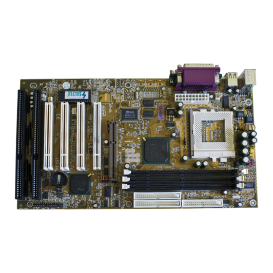
SL-65F INTEL 82440ZX SOCKET-370 F E A T U R E PROCESSOR Supports Intel PPGA Celeron 370 CPUs 300 ~ 533MHz or higher. Supports Intel FC-PGA Pentium III (Coppermine) CPUs 500E ~ 750 MHz or higher. Supports Cyrix Joshua CPUs. Supports 66/ 75*/ 83*/ 100/ 103*/ 112*/ 124*/ 133*/ 140*/ 150*MHz system bus speeds. - Page 5 M O T H E R B O A R D D I A G R A M JP21 JP22 FAN1 JP20 JP20/JP21/JP22 Intel 1-2 SHORT Cyrix 2-3 SHORT Intel 82440ZX Controller JP10 JP11 JP12 JP13 ES1938S PCI 1 JP14 JP15 JVGA1 JP16...
- Page 6 SYSTEM MEMORY CONFIGURATION The 82440ZX motherboard supports 168 pins DIMM of 4MB, 8MB, 16MB, 32MB, 64MB, 128MB and 256MB to form a memory sie between 8MB to 256MB(SDRAM). 82440ZX chipset provides “Table-Free” function, but do remember that the DRAM must be 3.3V Unbuffered and 4 clock type. User can use two DIMMs without any limit but if uses three DIMMs then must follow the rules below: DIMM1...
-
Page 7: Cpu Type Configuration
C P U C L O C K S E T T I N G CPU Type Configuration CPU MODEL BUS RATIO BUS CLOCK JP12 Pentium III 533EB/133 JP13 (133MHz * 4.0x) JP14 JP15 Celeron 300/66 JP12 (66MHz * 4.5x) JP13 Pentium III 600EB/133 JP14... -
Page 8: Jumper Setting
J U M P E R S E T T I N G A1 A2 A1 : 1st HDD LED A2 : 2nd HDD LED B. : INFRARED (IR) C. : POWER SWITCH D. : SUSPEND CONNECTOR E. : SPEAKER F. - Page 9 JP4 / JP5: CPU Host Clock Select CPU Host Clock JP4 / JP5 Auto (default) 100MHz (overlock) JP10 / JP11: USB Port Select USB Port JP10 / JP11 Redirect USB port1 to USB connector (default) Redirect USB port1 to AGP JP17: Power Lost Resume This jumper allows user to use the switch of ATX power supply to control ON/ OFF switch directly instead of using the power switch on the motherboard.
- Page 10 JVGA1: VGA Use This jumper is set for the PCI VGA card only. Open this jumper when the system is not able to boot up. If you use AGP card, it is important to set default with JVGA1. JVGA1 For PCI VGA card Normal (default) JBAT1: Clear CMOS data Clear the CMOS memory by shorting this jumper 2 &...
- Page 11 JP12 / JP13 / JP14 / JP15: Bus Ratio Select BUS RATIO BUS RATIO JP12~JP15 JP12~JP15 JP12 JP12 JP13 JP13 2.0x 2.5x JP14 JP14 JP15 JP15 JP12 JP12 JP13 JP13 3.0x 3.5x JP14 JP14 JP15 JP15 JP12 JP12 JP13 JP13 4.0x 4.5x JP14...
- Page 12 65F+ BIOS This Intel 82440ZX chipset comes with the AWARD BIOS from AWARD Soft- ware Inc. Enter the AWARD BIOS program Main Menu by: 1. Turn on or reboot the system. After a series of diagnostic checks, the following message will appear: PRESS <DEL>...
-
Page 13: Standard Cmos Setup
65F+ BIOS STANDARD CMOS SETUP Standard CMOS Setup allows you to record some basic system hardware con- figuration and set the system clock and error handling. You only need to modify the configuration values of this option when you change your system hardware configuration or the configuration stored in the CMOS memory gets lost or damaged. - Page 14 65F+ BIOS Date (mm:dd:yy) Set the current date and time. Time (hh:mm:ss) Primary (Secondary) This field records the specification for all non-SCSI Hard Disk Drives installed in your system. Refer to the respective docu- Master / Slave mentation on how to install the drives. Set the field to the type(s) of Floppy Disk drive(s) installed in Drive A / B your system.
-
Page 15: Bios Features Setup
65F+ BIOS BIOS FEATURES SETUP BIOS Features Setup allows you to improve your system performance or set up system features according to your preference. Run the BIOS Features Setup as follows: 1. Choose “BIOS FEATURES SETUP” from the Main Menu and a screen with a list of options will appear. - Page 16 65F+ BIOS Enabled: Activates automatically when the system boots up Virus Warning causing a warning message to appear if there is anything attempting to access the boot sector or Hard Disk partition table. Disabled: No warning message will appear when there is something attempting to access the boot sector or Hard Disk partition table.
- Page 17 65F+ BIOS Enabled (default): During POST, BIOS checks the track num- Boot Up Floppy Seek ber for Floppy Disk drive to see whether it’s 40 or 80 tracks. Disabled: During POST, BIOS will not check the track num- ber for Floppy Disk drive. Boot Up NumLock On (default): Activate the NumLock function at boot up.
- Page 18 65F+ BIOS OS Select for DRAM > Non-OS2 (default): For Non-OS/2 operating system. OS: For OS/2 operating system. 64MB Report No FDD For Yes: BIOS reports “NO FDD” to Win95. No (default): BIOS will not report “NO FDD” to Win95. WIN95 Video BIOS Shadow Enabled (default): Map the VGA BIOS to system RAM.
-
Page 19: Chipset Features Setup
65F+ BIOS CHIPSET FEATURES SETUP Chipset Features Setup changes the values of the chipset registers. These registers control the system options. Run the Chipset Features Setup as follows: 1. Choose “CHIPSET FEATURES SETUP” from the Main Menu and a screen with a list of options will appear. 2. - Page 20 65F+ BIOS Auto Configuration Choose Enabled (default) or Disabled. The system sets all options on the left of the screen automatically when you choose enabled. EDO DRAM Speed Choose 50ns or 60ns (default). Don’t change this setting un- less you know the DRAM access time spec. Selection EDO CASx# MA Wait You could select the timing control type of the EDO DRAM...
- Page 21 65F+ BIOS Memory Hole At 15M- Choose Enabled or Disabled (default). In order to improve performance, certain space in memory can be reserved for ISA cards. This memory must be mapped into the memory’s space below 16MB. Enable this option will cause memory only connect to 16MB.
- Page 22 65F+ BIOS Auto Detect DIMM/PCI Choose Disabled (default) or Enabled. The clock generator will turn off the DIMM clock if this slot is empty. Spread Spectrum Choose Disabled (default) or Enabled. This function is de- signed to EMI test only. CPU Host Clock (CPU/ Select the CPU Host Clock.
-
Page 23: Power Management Setup
65F+ BIOS POWER MANAGEMENT SETUP Power Management Setup changes the system power savings function. Run the Power Management Setup as follows: 1. Choose “POWER MANAGEMENT SETUP” from the Main Menu and a screen with a list of options will appear. 2. - Page 24 65F+ BIOS Enabled: Turn on ACPI function. ACPI Function Disabled (default): Turn off ACPI function. Choose Max. Saving, User Define (default), Disabled, or Min. Power Management Saving. PM Control By APM Choose Yes (default) or No. You need to choose Yes when the operating system has the APM functions, otherwise choose No.
- Page 25 65F+ BIOS Enabled: The system can not enter the power saving mode PCI / VGA Act-Monitor when monitor is on. Disabled (default): The system can enter the power saving mode when monitor is on. Instant-Off (default): Turn off the system power at once after Soft-Off By PWR-BTTN pushing the power button.
- Page 26 65F+ BIOS The following is a list of IRQ’s(Interrupt ReQuests), which can be exempted much as the COM ports and LPT ports above can. When an I/O device wants to gain the attention of the operating system, it signals this by causing an IRQ to occur. When the operating system is ready to respond to the request, it interrupts itself and performs the service.
-
Page 27: Pnp/Pci Configuration Setup
65F+ BIOS PnP/PCI CONFIGURATION SETUP PnP/PCI Configuration Setup defines PCI bus slots. Run the PnP/PCI Configuration Setup as follows: 1. Choose “PnP/PCI CONFIGURATION SETUP” from the Main Menu and a screen with a list of options will appear. 2. Use one of the arrow keys to move between options and modify the selected options by using PgUp/PgDn/+/- keys. - Page 28 65F+ BIOS Yes: OS supportsss Plug and Play function. PNP OS Installed No (default): OS doesn’t support Plug and Play function. Resources Controlled Choose Manual (default) or Auto. The BIOS checks the IRQ/ DMA chaannel number on the ISA and PCI card manually if you choose Manual.
-
Page 29: Load Setup Defaults
65F+ BIOS LOAD SETUP DEFAULTS Load Setup Defaults option loads the default system values to the system configuration fields. If the CMOS is corrupted the defaults are loaded automatically. Choose this option and the following message will appear: “Load Setup Defaults (Y/N)? N” To use the Setup Defaults, change the prompt to “Y”... -
Page 30: Integrated Peripherals
65F+ BIOS INTEGRATED PERIPHERALS Integrated Peripherals option changes the values of the chipset registers. These registers control system options in the computer. Run the Integrated Peripherals as follows: 1. Choose “INTEGRATED PERIPHERALS” from the Main Menu and a screen with a list of options will appear. 2. - Page 31 65F+ BIOS Primary Choose Auto (default) or Mode 0~4. The BIOS will detect the Master/Slave PIO HDD mode type automatically when you choose Auto. You need to set to a lower mode than Auto when your hard disk Secondary becomes unstable. Master/Slave PIO Primary Master/Slave Enabled (default): Turn on the onboard IDE function.
- Page 32 65F+ BIOS Choose Standard (default), HPSIR or ASKIR. UART Mode Select UART2 Duplex Mode Choose Half (default) or Full. RxD, TxD Active Choose Lo,Lo (default) / Lo,Hi / Hi,Hi / Hi,Lo. IR Transmission Delay Enabled: Enable delay when transferring data. Disabled (default): Disable delay when transferring data.
- Page 33 65F+ BIOS When user sets a password for keyboard, the password user KB Power On Password set that return the system to Full On state. Hot Key Power On Boot up the system via predetermined keyboard hot key. The choice: <Ctrl> + <F1>...<F12> 3.
-
Page 34: Supervisor/User Password
65F+ BIOS SUPERVISOR/USER PASSWORD These two options allow you to set your system passwords. Normally, the supervisor has a higher ability to change the CMOS setup option than the user. The way to set up the passwords for both supervisor and user are as follows: 1. -
Page 35: Ide Hdd Auto Detection
65F+ BIOS IDE HDD AUTO DETECTION IDE HDD Auto Detection detects the parameters of an IDE Hard Disk drive and automatically enters them to the Standard CMOS Setup screen. The screen will ask you to select a specific Hard Disk for Primary Master after you selected this option. -
Page 36: Flash Memory Update Installation
Appendix A APPENDIX A FLASH MEMORY UPDATE INSTALLATION 1. Download BIOS files and flash utility from your board vendor. They are: awdflash.exe and .bin file. 2. Copy them to bootable diskette and boot from diskette. 3. The diskette cannot include memory manager e.g. emm386.exe,qemm and himem.sys, otherwise there will appear an error message “insufficient memory”. -
Page 37: Appendix Bdriver Installation
Appendix B APPENDIX B DRIVER INSTALLATION If you are using Windows 98 SE, you do not need to install the 4-in-1 driver as the IRQ Routing Driver and the ACPI Registry are already incorpo- rated into the operating system. Users with Windows 98 SE may update the IDE Busmaster and AGP drivers by installing them individually. - Page 38 Appendix B VIA PCI IRQ Routing Miniport for Windows 9x Installation Windows95/Windows98: 1. Go to the CD-ROM disk, we suggest the CD-ROM title is D:\. 2. Find and run D:\Patch\Via\Virq9x\Setup.exe Note: Before install Windows98, user must enable two functions for this miniport driver in the BIOS menu, one is “OnChip USB”...
-
Page 39: Thermal Sensor
Appendix C APPENDIX C THERMAL SENSOR Thermal Sensor Connector a: Connect to RT2. b: Connect this thermal sensor to particular device which gener- ates lots of heat such as Hard Disk, VGA chip, etc. When connected, user could observe the temperature change from the BIOS program.
Need help?
Do you have a question about the SL-65F+ and is the answer not in the manual?
Questions and answers