Table of Contents
Advertisement
Quick Links
Advertisement
Table of Contents

Related Manuals for SOLTEK SL-65MIE


Summary of Contents for SOLTEK SL-65MIE
- Page 1 SL-65MIE USER MANUAL V1.2...
- Page 2 In no event shall Soltek Computer inc. be liable for any loss or profits, loss of business, loss of use or data, interruption of business, or for indirect, special, incidental, or con- sequential damages of any kind, even if Soltek Computer inc.
- Page 3 SOLTEK AROUND THE WORLD SOLTEK COMPUTER INC. Address : 7F, No. 306-3, Ta-Tung Rd, Sec.1, Hsi-Chih, Taipei- Hsien, Taiwan, R.O.C. Telephone : 886-2-2642-9060 : 886-2-2642-9065 E-mail : sales@soltek.com.tw Web site : http://www.soltek.com.tw SOUL TECHNOLOGY EUROPE B.V. Address : Hongkongstraat 55 3047 BR, Rotterdam, The...
-
Page 4: Table Of Contents
65MIE C O N T E N T CHAPTER 1 INTRODUCTION ........8 1- 1 MAINBOARD SPECIFICATION ........... 9 1-1-1 PROCESSOR ..................9 1-1-2 CHIPSET ..................... 9 1-1-3 INTEGRATED SDRAM CONTROLLER ..........9 1-1-4 FULL FEATURED ACCELERATED GRAPHICS PORTS ....9 (AGP) CONTROLLER ................ - Page 5 Content 2-5-6 USB PORT SELECT (JP17/JP18) ............ 24 2-5-7 USB PORT SELECT (JP19/JP20) ............ 24 2-5-8 FACTORY DEFAULT (J1) ..............25 2-6 CONNECTORS CONFIGURATIONS ......... 26 2-6-1 ONBOARD FAN CONNECTOR (CPUFA1/AUXFA1/CHAFA1) ..26 2-6-2 CD-ROM AUDIO CONNECTOR (CD32/CD33) ........ 27 2-6-3 WAKE ON LAN FUNCTION (JWOL1) ..........
- Page 6 65MIE 4-5-1 BEFORE UPGRADING BIOS ............47 4-5-2 UPGRADE PROCESS ..............47 4-6 BIOS SETUP-- CMOS SETUP UTILITY ........51 4-6-1 STANDARD CMOS SETUP .............. 52 4-6-2 ADVANCED BIOS FEATURES ............55 4-6-3 ADVANCED CHIPSET FEATURES ..........60 4-6-4 INTEGRATED PERIPHERALS ............64 4-6-5 POWER MANAGEMENT SETUP .............
- Page 7 Chapter 1 Introduction ITEMLIST CHECKUP ====== Mainboard Support CD User’s Manual Bundled Bonus Pack CD Bundled Bonus Pack Manual Temperature Sensor Cable ATA66/100 IDE Cable RS232 Cable FDD Cable...
-
Page 8: Chapter 1 Introduction
65MIE CHAPTER INTRODUCTION • This chapter briefly introduces the characteristics of this mainboard. It includes the information regarding the chipset, CPU types, built-in functions and layout. Users will have more ideas about mainboards after reading this chapter. THIS CHAPTER CONTAINS THE FOLLOWING TOPICS : 1-1 MAINBOARD SPECIFICATION 1-2 MAINBOARD LAYOUT 1-3 CHIPSET DIAGRAM... -
Page 9: Mainboard Specification
Chapter 1 Introduction 1- 1 MAINBOARD SPECIFICATION 1-1-1 PROCESSOR • Supporting Intel ® FC-PGA Pentium !!! up to 1GHz. ® • Supporting Intel FC-PGA 370 Celeron & PPGA 370 Celeron up to 850MHz. • Supporting VIA Cyrix !!! up to 800MHz. •... -
Page 10: Multi-I/O Function
65MIE 1-1-5 MULTI-I/O FUNCTION • Integrated IDE Controller. • Supporting Ultra ATA33/66/100, BMIDE and PIO modes. • Two UARTs for complete Serial Ports. • One dedicated IR connector: --Third serial port dedicated to IR function either through the two complete serial ports or the third dedicated port Infrared-IrDA (HPSIR) and ASK( Amplitude Shift Keyed) IR. -
Page 11: Form Factor
Chapter 1 Introduction • System event monitoring with two event classes • Supporting PS/2 keyboard & Mouse power on • Supporting Wake On LAN (WOL) & Wake On Modem • Supporting real time clock (RTC) with date alarm, month alarm, and cen- tury field •... -
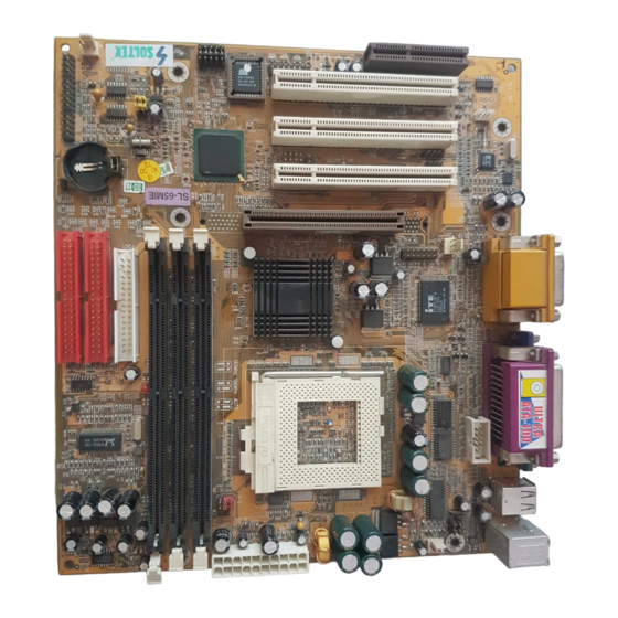
Page 12: Motherboard Layout
65MIE 1-2 MOTHERBOARD LAYOUT --- 65MIE CPUFAN1 ATX POWER Clock Generator COM2 Intel 815E GMCH SCR1 AGP 4X AUXFA1 PCI 1 Battery Intel CD32 AC'97 Codec PCI 2 ICH2 CD33 JWOL1 PCI 3 CHAFA1 CNR 1 USB2 Using non-compliant memory with higher bus clock than default frequency (over clocking) may severely compromise the reliability of system. -
Page 13: Chipset System Block Diagram
Chapter 1 Introduction 1-3 CHIPSET SYSTEM BLOCK DIAGRAM Soket 370 Processor System Bus (66/100/133MHz) Intel 82815 Chipset 64bit / Intel 82815 66/100/133MHz System (GMCH) Memory -Memory Controller Analog Display -AGP Controller AGP Connector -Graphics Controller -3D Engine AGP Graphics -2D Engine AGP 2.0 Display Cache -Video Engine... - Page 14 65MIE MEMO...
-
Page 15: Chapter 2 Hardware Setup
Chapter 2 Hardware Setup CHAPTER HARDWARE SETUP ATTENTION !!! 1. Please refer to your processor installation or other documentation attached with your CPU for more detailed installing instruction. 2. Installing a heat sink and cooling fan is necessary for proper heat dissipation from your CPU. Incorrect installation may result in overheating and damage of your CPU. -
Page 16: Cpu Installation
65MIE 2- 1 CPU INSTALLATION WARNING !!! Never run you processor without the heat sink properly and firmly attached. PERMANENT DAMAGE WILL RESULT! • Pull out the lever from the socket, and then raise the le- ver up to a 90-degree angle. •... -
Page 17: Memory Installation
Chapter 2 Hardware Setup 2- 2 MEMORY INSTALLATION WARING !!! • Make sure that you unplug your power supply when adding or removing memory modules or other system components, failure to do so may cause severe damage to both your mainboard and expansion cards. •... -
Page 18: Supported System Bus And System Memory Bus Frequencies Table
65MIE 2-3 SUPPORTED SYSTEM BUS AND SYSTEM MEMORY BUS FREQUENCIES TABLE • The 82815E GMCH has a new type of clocking architecture. It has inte- grated SDRAM buffers that run at either 100 or 133 MHz, independent of the system bus frequency. See table below for supported system bus and system memory bus frequencies. -
Page 19: Hdd/Fdd Installation
Chapter 2 Hardware Setup 2- 4 HDD/FDD INSTALLATION • To install HDD (Hard Disk Drive), you may connect the cable’s blue connector to the mainboard’s primary (IDE1) or secondary IDE connector, and then connect the gray connector to your slave device and the black connector to your master device. - Page 20 65MIE • To install FDD (Floppy Disk Drive), connect the end with single connector to the mainboard, and connect other end with two connectors to the floppy drives. CPUFAN1 ATX POWER Clock Generator Floppy Disk Drive Connector: COM2 Orient the red line on the floppy ribbon cable to Pin1.
-
Page 21: Jumper Setting For Devices On Board
Chapter 2 Hardware Setup 2- 5 JUMPER SETTING FOR DEVICES ON BOARD: • The following diagrams show the location for jumper blocks on the mainboard. CAUTION • Do not remove the jumper when power is on. Always make sure the power is off before changing any jumpers. -
Page 22: Keyboard Power On (Jp2)
65MIE 2-5-2 KEYBOARD POWER ON (JP2) CPUFAN1 ATX POWER Clock Generator COM2 Keyboard Power On (JP2) Intel 815E GMCH SCR1 Disabled (default) AGP 4X AUXFA1 PCI 1 Battery Intel CD32 AC'97 Codec PCI 2 ICH2 CD33 Enabled JWOL1 PCI 3 CHAFA1 CNR 1 USB2... -
Page 23: Bus Clock Select (Jp7/Jp8)
Chapter 2 Hardware Setup 2-5-4 BUS CLOCK SELECT (JP7/JP8) CPUFAN1 ATX POWER Clock Generator COM2 Bus Clock Select (JP7/JP8) Intel 815E 66MHz / 100MHz / 133MHz GMCH SCR1 Auto Select (default) AGP 4X AUXFA1 PCI 1 Battery Intel CD32 AC'97 Codec PCI 2 ICH2... -
Page 24: Usb Port Select (Jp17/Jp18)
65MIE 2-5-6 USB PORT SELECT (JP17/JP18) CPUFAN1 ATX POWER Clock Generator COM2 USB Port Select (JP17/JP18) Intel 815E GMCH SCR1 Redirect USB port 0 AGP 4X to USB1 connector (default) AUXFA1 PCI 1 Battery Intel CD32 AC'97 Codec PCI 2 ICH2 CD33 Redirect USB port 0... -
Page 25: Factory Default (J1)
Chapter 2 Hardware Setup 2-5-8 FACTORY DEFAULT (J1) CPUFAN1 ATX POWER Clock Generator COM2 Intel 815E GMCH SCR1 AGP 4X AUXFA1 PCI 1 Battery Intel CD32 AC'97 Codec PCI 2 ICH2 CD33 JWOL1 PCI 3 CHAFA1 CNR 1 USB2 This jumper is only for factory test. -
Page 26: Connectors Configurations
65MIE 2-6 CONNECTORS CONFIGURATIONS • This section lists out all connectors configurations for users’ reference: 2-6-1 ONBOARD FAN CONNECTOR (CPUFA1/AUXFA1/ CHAFA1) CPUFAN1 ATX POWER Onboard FAN Connector (CPUFA1/ AUXFA1/CHAFA1) Clock Generator COM2 CPUFA1 CPU FAN Intel SYSTEM FAN 815E AUXFA1 GMCH SCR1 AGP 4X... -
Page 27: Cd-Rom Audio Connector (Cd32/Cd33)
Chapter 2 Hardware Setup 2-6-2 CD-ROM AUDIO CONNECTOR (CD32/CD33) CPUFAN1 CD32 ATX POWER CD33 Clock Generator COM2 CD-ROM Audio Connector (CD32/ CD33) Intel 815E GMCH SCR1 PIN NO. CD32 CD33 AGP 4X AUXFA1 PIN 1 Left Channel PCI 1 Battery Left Channel Intel PIN 2... -
Page 28: Thermal Sensor Connector (Rt2)
65MIE 2-6-4 THERMAL SENSOR CONNECTOR (RT2) CPUFAN1 ATX POWER Clock Generator COM2 Thermal Sensor Connector (RT2) Intel 815E GMCH SCR1 AGP 4X AUXFA1 PCI 1 Battery Intel CD32 AC'97 Codec PCI 2 ICH2 CD33 JWOL1 PCI 3 CHAFA1 CNR 1 USB2 We provide a thermal cable in the mainboard package. -
Page 29: Complex Header J2&J3
Chapter 2 Hardware Setup 2-6-5 COMPLEX HEADER J2&J3 • This complex Header consists of 9 connectors providing various supports: J2J3 15 15 SUSPEND LED SMI SIGNAL SUSPEND LED SIGNAL POWER SWITCH ATX POWER SWITCH NO CONNECTION NO CONNECTION NO CONNECTION POWER LED NO CONNECTION NO CONNECTION... -
Page 30: Chassis Panel Connector
65MIE 7. J3 Reset Switch Connector: CONNECTION: Connected to the case-mounted “Reset Switch”. FUNCTION: To supply power to “Reset Switch” and support system re-boot function. 8. J3 Speaker Connector: CONNECTION: Connected to the case-mounted Speaker. FUNCTION: To supply power to the case-mounted Speaker. 2-6-6 CHASSIS PANEL CONNECTOR A : PS/2 MOUSE PORT B : USB 0 PORT... -
Page 31: Serial Port Connectors
Chapter 2 Hardware Setup 2-6-7 SERIAL PORT CONNECTORS • One serial port is ready for a mouse or other serial devices. A second serial port is available using a serial port bracket connected from the motherboard to an expansion slot opening. COM2 PIN1 VT8605... -
Page 32: Smart Card Reader Connector (Scr1)
65MIE 2-6-8 SMART CARD READER CONNECTOR (SCR1) • The connector “SCR1” allows you to use Smart Card Reader. It compliant with Personal Computer Smart Card (PC/SC) working group standard and smart card (ISO 7816) protocols. CPUFAN1 ATX POWER Clock Generator COM2 Intel SCRPRES#... -
Page 33: Communication And Networking Riser Slot (Cnr)
Chapter 2 Hardware Setup 2-6-10 COMMUNICATION AND NETWORKING RISER SLOT (CNR) • This connector allows you to use network, modem or audio riser cards. CPUFAN1 ATX POWER Clock Generator COM2 Intel 815E GMCH SCR1 AGP 4X AUXFA1 PCI 1 Battery Intel CD32 AC'97... -
Page 34: Second Usb Header (Usb2)
65MIE 2-6-12 SECOND USB HEADER (USB2) • This header is for the additional USB cable to provide you two additional USB ports. Users can order the additional USB cable from your mainboard dealers or venders. Additional USB Cable (Optional) Black Black Green Green... -
Page 35: Irqs Description For Various Devices
Chapter 2 Hardware Setup 2-6-13 IRQs DESCRIPTION FOR VARIOUS DEVICES Function Description Priority IRQ 0 System Timer IRQ 1 Keyboard Controller IRQ 2 Programmable Interrupt IRQ 3 Serial Port (COM 2) IRQ 4 Serial Port (COM 1) IRQ 5 Free IRQ 6 Floppy Disk Controller IRQ 7... - Page 36 65MIE MEMO...
-
Page 37: Chapter 3 Software Setup
Chapter 3 Software Setup CHAPTER SOFTWARE SETUP ABOUT SUPPORT CD • In Support CD, it contains most information for users’ requirement, such as Acrobat Reader, BIOS, Users’ full version Manual, Driver, Hardware Monitor (if motherboard supports this function), Patch, and Utilities etc., User can browse the CD and get further details in regard of our motherboard. -
Page 38: Intel Chipset Driver Installation
65MIE 3-1 INTEL CHIPSET DRIVER INSTALLATION • When a welcome window • Please put the Support CD appears on the screen, into the CD-ROM drive. choose “Install Driver”. • Click on the “INTEL • Click on the “INF Utility Chipsets Driver”. for All INTEL Chipsets”. -
Page 39: Intell Ultra Ata Storage Driver Installation
Chapter 3 Software Setup 3-2 INTELL ULTRA ATA STORAGE DRIVER INSTALLATION • Please put the Support CD • When a welcome window into the CD-ROM drive. appears on the screen, choose “Install Driver”. • Click on the “INTEL • Click on the “INTEL 815EP Driver”. - Page 40 65MIE • Press “Next” to continue. Next • Press “Next” to continue. Next • After all the setup process is finished, please restart your computer by clicking on Finish. Finish...
-
Page 41: Ac'97 Driver Installation
Chapter 3 Software Setup 3-3 AC’97 DRIVER INSTALLATION • Please put the Support CD • When a welcome window into the CD-ROM drive. appears on the screen, choose “Install Driver”. • Click on the “INTEL • Click on the “INTEL 815EP Driver”. -
Page 42: Installing Ite Hardware Monitor Utility (Smartguardiam)
65MIE 3-4 INSTALLING ITE HARDWARE MONITOR UTILITY (SMARTGUARDIAM) • Please put the Support CD • When a welcome window into the CD-ROM drive. appears on the screen, choose “Install Driver”. • Click on the “INTEL • Click on the “INTEL 815EP Driver”. - Page 43 Chapter 3 Software Setup This screen shows the ITE SMARTGUARDIAM, it shows the information about system temperatures, voltages and Fan speed. You can also change some Value settings to for your system to optimize its performance.
- Page 44 65MIE MEMO...
-
Page 45: Chapter 4 Bios Setup
Chapter 4 BIOS Setup CHAPTER BIOS SETUP THE BIOS • BIOS stands for Basic Input and Output System. It is sometimes called ROM BIOS because it is stored in a Read-Only Memory (ROM) chip on the mainboard. BIOS is the first program to run when you turn on your computer. •... -
Page 46: What Is Bios Setup
65MIE 4-1 WHAT IS BIOS SETUP • BIOS Setup is an interactive BIOS program that you need to run when: 1. Changing the hardware of your system. (for example: installing a new Hard Disk etc..) 2. Modifying the behavior of your computer. (for example: changing the sys- tem time or date, or turning special features on or off etc..) 3. -
Page 47: Before Upgrading Bios
Chapter 4 BIOS Setup replace an EPROM component. • The upgrade utility can be loaded on a floppy diskette and used to provide the capability to save, verify, and update the system BIOS. The upgrade utility can also be run from a hard disk drive or a network drive. 4-5-1 BEFORE UPGRADING BIOS •... - Page 48 65MIE specific mainboard.) Step 5. Please press <F1> or <F10> to exit or reset your system, Warning ! If the message “Write Fail” appears while Award “FLASH MEMORY WRITER” is verifying Flash memory, just repeat the process. Please DO NOT reset or turn off the system.
- Page 49 Chapter 4 BIOS Setup Figure 4-5-1 Award Flash Memory Writer Start Screen Figure 4-5-2 Award Flash Memory Writer Complete Screen...
- Page 50 65MIE The parameters of AWDFLASH.EXE /sn: No original BIOS backup /py: Program flash memory /cc: Clear CMOS data (and update data automatically) after programming NOTE: Users can type AWDFLASH /? to get further details about the parameters. Incorrect usage of the parameter will damage the BIOS information, so we strongly recommend users to leave parameters alone unless you fully understand their function.
-
Page 51: Bios Setup-- Cmos Setup Utility
Chapter 4 BIOS Setup 4-6 BIOS SETUP-- CMOS SETUP UTILITY • This mainboard comes with the AWARD BIOS from AWARD Software Inc. Enter the CMOS Setup Utility Main Menu by: 1. Turn on or reboot your system. After a series of diagnostic checks, the following message will appear: PRESS <DEL>... -
Page 52: Standard Cmos Setup
65MIE 4-6-1 STANDARD CMOS SETUP • Standard CMOS Setup records some basic system hardware configuration and sets the system clock and error handling. You only need to modify the configuration values of this option if you want to change your system hard- ware configuration or when the data stored in the CMOS memory gets lost or damaged. - Page 53 Chapter 4 BIOS Setup Date (mm:dd:yy) The BIOS determines the day of the week from the other date information. This field is for information only. Press the left or right arrow key to move to the de- sired field (date, month, year). Press the PgUp or PgDn key to increment the setting, or type the de- sired value into the field.
- Page 54 65MIE Halt On Set this warning feature for the type of errors that will cause the system to halt. The choices are: All Errors; Post stops for all error. No Errors; Post does not stop for any error. All, But Keyboard; Post stops for all, but not for keyboard error.
-
Page 55: Advanced Bios Features
Chapter 4 BIOS Setup 4-6-2 ADVANCED BIOS FEATURES • ADVANCED BIOS FEATURES improves your system performance or sets up system features according to your preference. Run the ADVANCED BIOS FEATURES as follows: 1. Choose “ADVANCED BIOS FEATURES” from the Main Menu and a list of options will appear: 2. - Page 56 65MIE CMOS Setup Utility - Copyright (C) 1984-2001 Award Software Advanced BIOS Features Virus Warning Disabled Item Help CPU Internal Cache Enabled Menu Level External Cache Enabled CPU L2 Cache ECC Checking Enabled Processor Number Feature Disabled Quick Power On Self Test Enabled First Boot Device Floppy...
- Page 57 Chapter 4 BIOS Setup Virus Warning Enabled: Activates automatically when the system boots up showing a warning message if anything attempts to access the boot sec- tor or hard disk partition table. Disabled: No warning message will appear when there is something attempting to access the boot sector or hard disk partition table.
- Page 58 65MIE Swap Floppy Drive When enabled, floppy drives A and B will be exchang- ing status without any physical connection and modi- fication on the cables. Boot Up Floppy Seek When enabled, the BIOS tests (seeks) floppy drives to determine whether they have 40 or 80 tracks. Only 360-KB floppy drives have 40 tracks;...
- Page 59 Chapter 4 BIOS Setup Security Option If you have set a password, select whether the pass- word is required every time the System boots, or only when you enter setup. The choices: system; setup. OS Select For DRAM > Select OS2 only if you are running OS/2 operating 64MB system with greater than 64MB of RAM on your system.
-
Page 60: Advanced Chipset Features
65MIE 4-6-3 ADVANCED CHIPSET FEATURES • ADVANCED CHIPSET FEATURES is used to modify the values of chipset registers. These registers control the system options. Run the ADVANCED CHIPSET FEATURES as following: 1. Choose “ADVANCED CHIPSET FEATURES” from the Main Menu and a list of options will appear: 2. - Page 61 Chapter 4 BIOS Setup CMOS Setup Utility - Copyright (C) 1984-2001 Award Software Advanced Chipset Features Item Help SDRAM CAS Latency Time Menu Level SDRAM Cycle Time Tras/Trc SDRAM RAS-To-CAS Delay SDRAM RAS Precharge Time System BIOS Cacheable Disabled Video BIOS Cacheable Disabled Memory Hole At 15M-16M Disabled...
- Page 62 65MIE SDRAM CAS Latency When synchronous DRAM is installed, the number of Time clock cycles of CAS latency depends on the DRAM timing. Do not reset this field from the default value specified by the system designer. SDRAM Cycle Time Select the number of SCLKs for an access cycle.
- Page 63 Chapter 4 BIOS Setup CPU Latency Timer Please use Default setting. Delayed Transaction The chipset has an embedded 32-bit posted write buffer to support delay transactions cycles. Select Enabled to support compliance with PCI speci- fication version 2.1. AGP Graphics Aper- Series of options are available: 4, 8, 16, 32, 64, 128 ture Size or 256 MB.
-
Page 64: Integrated Peripherals
65MIE 4-6-4 INTEGRATED PERIPHERALS • INTEGRATED PERIPHERALS option allows you to get some information inside your system when it is working. Run the INTEGRATED PERIPHERALS as follows: 1. Choose “INTEGRATED PERIPHERALS” from the Main Menu and a list of options will appear: 2. - Page 65 Chapter 4 BIOS Setup CMOS Setup Utility - Copyright (C) 1984-2001 Award Software Integrated Peripherals Item Help On-Chip Primary PCI IDE Enabled On-Chip Secondary PCI IDE Enabled Menu Level IDE Primary Master PIO Auto IDE Primary Slave PIO Auto IDE Secondary Master PIO Auto IDE Secondary Slave PIO Auto...
- Page 66 65MIE On-Chip Primary/ The chipset contains a PCI IDE interface with sup- Secondary PCI IDE port from two IDE channels. Select Enabled to acti- vate the first and/or the second IDE interface. Select Disabled to deactivate an interface if you install a pri- mary and/or second add-on IDE interface.
- Page 67 Chapter 4 BIOS Setup Onboard/CNR LAN Use the default setting. Selection The choice: Auto; Onboard IDE HDD Block Mode Block mode is also called block transfer, multiple commands, or multiple sector read/write. If your IDE hard drive supports block mode (most new drives do), select Enabled for automatic detection of the optimal number of block read/write per sector the drive can support.
- Page 68 65MIE Onboard Parallel Port Select a logical LPT port name and matching address for the physical parallel (printer) port. The choices: 378H/IRQ7; 278H/IRQ5; 3BC/IRQ7; Disabled. Parallel Port Mode Select an operating mode for the onboard parallel (printer) port. Select Normal, Compatible, or SPP unless you are certain your hardware and software both support one of the other available modes.
-
Page 69: Power Management Setup
Chapter 4 BIOS Setup 4-6-5 POWER MANAGEMENT SETUP • POWER MANAGEMENT SETUP allows you to set the system’s power saving functions. Run the POWER MANAGEMENT SETUP as follows: 1. Choose “POWER MANAGEMENT SETUP” from the Main Menu and a list of options will appear: CMOS Setup Utility - Copyright (C) 1984-2001 Award Software Power Management Setup... - Page 70 65MIE 2. Use one of the arrow keys to move between options and modify the se- lected options by using PgUp / PgDn / + / - keys. <F1>: “Help” gives options available for each item. <F5>: Get the previous values. These values are the values with which the user starts the current session.
- Page 71 Chapter 4 BIOS Setup Video Off Method This determines the manner in which the monitor is blanked. o i t l l i c i t o i t e t i o i t t i r o i t t i n Video Off in Suspend This determines the manner in which the monitor is blanked.
- Page 72 65MIE Power On by Ring An input signal on the serial Ring Indicator (RI) line (in other words, an incoming call on the modem) awak- ens the system from a soft off state. The choice: Enabled, Disabled. USB KB Wake-Up This item will enable you to Wake-up the system by From S3 USB keyboard when you shut down the computer in...
-
Page 73: Pnp / Pci Configuration
Chapter 4 BIOS Setup 4-6-6 PNP / PCI CONFIGURATION • PNP/PCI CONFIGURATION allows you to modify the system’s power sav- ing functions. Run the PNP/PCI CONFIGURATION as follows: 1. Choose “PNP/PCI CONFIGURATION” from the Main Menu and a list of options will appear: CMOS Setup Utility - Copyright (C) 1984-2001 Award Software PnP/PCI Configurations... - Page 74 65MIE Reset Configuration Normally, you leave this Disabled. Select Enabled to Data reset Extended System Configuration Data (ESCD), when you exit Setup if you have installed a new add- on and the system reconfiguration has caused such a serious conflict that the operating system cannot boot.
- Page 75 Chapter 4 BIOS Setup PCI/VGA Palette Snoop This option allows the BIOS to preview VGA status, and to modify the information delivered from the fea- ture Connector of the VGA card to MPEG card. This option can solve the display inversion to black after you have used MPEG card.
-
Page 76: Pc Health Status
65MIE 4-6-7 PC HEALTH STATUS • This section helps you to get more information about your system including CPU temperature, FAN speed and voltage. It is recommended that you contact your mainboard supplier to get proper value about your setting of the CPU temperature. -
Page 77: Frequency/Voltage Control
Chapter 4 BIOS Setup 4-6-8 FREQUENCY/VOLTAGE CONTROL Run the “FREQUENCY/VOLTAGE CONTROL” as follows: 1. Choose “FREQUENCY/VOLTAGE CONTROL” from the Main Menu and a list of options will appear: CMOS Setup Utility - Copyright (C) 1984-2001 Award Software Frequency Control Item Help Auto Detect DIMM/PCI Clk Enabled Spread Spectrum Modulated... - Page 78 65MIE Auto Detect This item allows you to enable/disable to detection of DIMM/PCI CLK DIMM/PCI Clock. The choices: Enabled; Disabled. Spread Spec- This item allows you to enable/disable the spread trum Modulated spectrum modulation. The choices: Enabled; Disabled. Linear Spread This item allows you to enable/disable the lineaer Model spread model.
-
Page 79: Load Optimized Defaults
Chapter 4 BIOS Setup • Press <ESC> to return to the Main Menu when you finish setting up all items. 4-6-9 LOAD OPTIMIZED DEFAULTS • When you press <Enter> on this item, you will get a confirmation dialog box with a message similar to: “... -
Page 80: Set Supervisor / User Password
65MIE 4-6-10 SET SUPERVISOR / USER PASSWORD • These two options allow you to set your system passwords. Normally, the supervisor has a higher priority to change the CMOS setup option than the users. The way to set up the passwords for both Supervisor and Users are as follows: 1. -
Page 81: Save & Exit Setup
Chapter 4 BIOS Setup 4-6-11 SAVE & EXIT SETUP • SAVE & EXIT SETUP allows you to save all modifications you have speci- fied into the CMOS memory. Highlight this option on the Main Menu and the following message appears: “SAVE to CMOS and EXIT (Y/N) ? Y “... -
Page 82: Appendices
65MIE APPENDICES THIS CHAPTER CONTAINS THE FOLLOWING TOPICS : APPENDIX-1 TECHNICAL TERMS INTRODUCTION APPENDIX-2 IDENTIFYING BIOS VERSION APPENDIX-3 IDENTIFYING MAINBOARD MODEL NUMBER... -
Page 83: Appendix-1 Technical Terms Introduction
A p p e n d i c e s APPENDIX-1 TECHNICAL TERMS INTRODUCTION Technical Terms Introduction Tech Term Meaning Accelerated Graphic Port Audio Modem Riser Advanced Communication Riser Central Processing Unit CMOS Complementary Metal Oxide Semiconductor CRIMM Continuity RIMM Communication and Networking Riser Direct Memory Access Desktop Management Interface... -
Page 84: Appendix-2 Identifying Bios Version And Bios Part
65MIE APPENDIX-2 IDENTIFYING BIOS VERSION AND BIOS PART NUMBER When you boot up your computer, you may see a screen which tells your computer is phoenixnet™ enabled, please see the example below. When the main screen Figure1 shows up, press “Tab” key to display BIOS information (Figure2). - Page 85 A p p e n d i c e s Figure2 shown below displays the BIOS version and BIOS part number identification. Figure 2 BIOS VERSION example: REV T2.1 BIOS ID STRING example: 6A69RSNCC...
-
Page 86: Number
65MIE APPENDIX-3 IDENTIFYING MAINBOARD / MODEL NUMBER Usually the mainboard model number is labeled on the side of ISA slot or PCI slot. Please see the picture shown below: MAINBOARD MODEL NUMBER example: SL-65KV2 MAINBOARD SERIAL NUMBER example: 0012000T005679... - Page 87 A p p e n d i c e s MEMO...
- Page 88 65MIE MEMO...
Need help?
Do you have a question about the SL-65MIE and is the answer not in the manual?
Questions and answers