
Related Manuals for SOLTEK SL-65EP


Summary of Contents for SOLTEK SL-65EP
- Page 1 T h e S o u l C o m p u t e r T e c h n o l o g y SL-65EP/65EP+ V1.0 USER MANUAL...
- Page 2 In no event shall Soltek computer inc. Be li- able for any loss or profits, loss of business, loss of use or data, interruption of business, or for indirect, special, incidental, or con- sequential damages of any kind, even if Soltek computer inc.
- Page 3 SOLTEK AROUND THE WORLD SOLTEK COMPUTER INC. Address : 7F, No. 306-3, Ta-Tung Rd, Sec.1, Hsi-Chin, Taipei- Hsien, Taiwan, R.O.C. Telephone : 886-2-2642-9060 : 886-2-2642-9065 E-mail : sales@soltek.com.tw Web site : http://www.soltek.com.tw SOLTEK KOREA INC. Address : 1002, Chungjin Bldg. 53-5 Wonhyo-Ro, 3-Ka,...
-
Page 4: Table Of Contents
65EP / 65EP+ C O N T E N T CHAPTER 1 INTRODUCTION ................7 1-1 ITEMLIST CHECKUP ................7 1-2 CPU ......................7 1-3 CHIPSET ....................7 1-4 INTEGRATED SDRAM CONTROLLER ..........7 1-5 BIOS ....................... 8 1-6 FULL FEATURED ACCELERATED GRAPHICS PORTS(AGP) CONTROLLER .................. - Page 5 65EP / 65EP+ 2-7.7 ONBOARD CREATIVE SOUND SELECT (JP21) ......23 2-7.8 CLEAR CMOS DATA (JBAT1/JBAT2) ..........23 2-7.9 BIOS BOOT BLOCK LOCK (JP16) ........... 23 2-7.10 WAKE ON LAN(WOL) FUNCTION (JWOL1) ........24 2-7.11 CD-ROM AUDIO CONNECTOR (CD_IN1/CD_IN2) ......24 2-7.12 TAD1/TV1 CONNECTOR ..............
- Page 6 65EP / 65EP+ 4-5 WHAT IS POST ..................49 4-6 BIOS UPGRADE .................. 49 4-6.1 BEFORE UPGRADE BIOS ............... 49 4-6.2 UPGRADE PROCESS ..............50 4-7 CMOS SETUP UTILITY ............... 53 4-8 STANDARD CMOS SETUP ..............54 4-9 ADVANCED BIOS FEATURES ............57 4-10 ADVANCED CHIPSET FEATURES ...........
-
Page 7: Introduction
65EP / 65EP+ CHAPTER 1 INTRODUCTION 1-1 ITEMLIST CHECKUP • Motherboard • Support CD • User’s Manual • Bundle Bonus Pack CD • Bundle Bonus Pack Manual • Temperature Sensor Cable • ATA66/100 IDE Cable • RS232 Cable • FDD Cable 1-2 CPU ®... -
Page 8: Bios
65EP / 65EP+ 1-5 BIOS • Award BIOS 6.0 • Supports Plug & Play V1.0. • FLASH MEMORY for easy upgrade. • Supports BIOS writing protection. • Year 2000 compliant. 1-6 FULL FEATURED ACCELERATED GRAPHICS PORTS(AGP) CONTROLLER • Provides 1x/ 2x/ 4x AGP controller •... -
Page 9: Form Factor
65EP / 65EP+ 1-9 FORM FACTOR • Micro ATX form factor 4 layers PCB. • Motherboard size: 20.0cm x 24.5cm 1-10 SOUND CONTROLLER • Build-in AC’97 Audio codec (for 65EP only). • Build-in creative CT5880 Audio chip (for 65EP+ only). 1-11 POWER MANAGEMENT •... -
Page 10: 1-13.1 Motherboard Layout
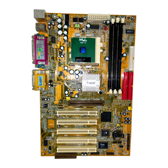
65EP / 65EP+ 1-13.1 MOTHERBOARD LAYOUT --- 65EP • Default Setting: Intel Celeron 300A/66 MHz CPUFA1 ATX POWER Clock Generator JP10 Intel 815EP AUXFA1 AGP PRO AC'97 CD_IN1 Codec PCI 1 CD_IN2 Intel PCI 2 ICH2 JBAT1 PCI 3 JBAT2 JP16 PCI 4 Battery... -
Page 11: 1-13.2 Motherboard Layout
65EP / 65EP+ 1-13.2 MOTHERBOARD LAYOUT --- 65EP+ • Default Setting: Intel Celeron 300A/66 MHz CPUFA1 ATX POWER Clock Generator JP10 Intel 815E AUXFA1 AGP PRO CD_IN1 PCI 1 CD_IN2 TAD1 Intel PCI 2 ICH2 JBAT1 PCI 3 JBAT2 JP16 PCI 4 Battery COM2... -
Page 12: Chipset System Block Diagram
65EP / 65EP+ 1-14 CHIPSET SYSTEM BLOCK DIAGRAM Intel Pentium III Processor Intel Celeron Processor System Bus (66/100/133MHz) Digital Video Out Intel 82815EP Chipset 64bit 66/ Intel 82815EP 100/133MHz System (MCH) AGP Connector Memory AGP Graphics -Memory Controller AGP 2.0 Display Cache -AGP Controller (4 MB SDRAM,... -
Page 13: Motherboard Specification Table Of 65Ep & 65Ep
65EP / 65EP+ 1-15 MOTHERBOARD SPECIFICATION TABLE OF 65EP & 65EP+ Model 65EP 65EP+ Memory Intel 82815EP (MCH) Controller Hub Intel 82801BA (ICH2) Controller Hub LPC I/O Chip ITE 8712 Supports PC133 and PC100 SDRAM up to 512GB Memory 3 DIMM Slots AGP Interface AGP 4X Pro Mode Audio... - Page 14 65EP / 65EP+ ATTENTION !!! 1. Please refer to your processor installation or other documentation attached with your CPU for detailed installing instruction. 2. Installing a heat sink and cooling fan is necessary for proper heat dissipation from your CPU. Uncorrected installation may result in overheating and damage of your CPU.
-
Page 15: Hardware Setup
65EP / 65EP+ CHAPTER 2 HARDWARE SETUP 2-1 CPU INSTALLATION WARNING !!! Never run you processor without the heat sink properly and firmly attached. PERMANET DAMAGE WILL RESULT! 1. Pull the lever sidways away from the socket, and then raise the lever up to a 90-degree angle. -
Page 16: Cpu Frequency
65EP / 65EP+ 3. Make sure that the CPU positions in the socket tightly, and then put the lever down to complete the CPU installation. 2-2 CPU FREQUENCY • The CPU’s “CPU CLOCK RATIO” and “CPU HOST/PCI CLOCK” set- tings are automatically detected to be default value by BIOS in the “Frequency/Voltage Control”... -
Page 17: Memory Installation
65EP / 65EP+ 2-3 MEMORY INSTALLATION WARING !!! • Make sure that you unplug your power supply when adding or removing memory modules or other system components, failure to do so may cause severe damage to both your motherboard and expansion cards. •... -
Page 18: Supported System Bus And System Memory Bus Frequencies Table
65EP / 65EP+ 2-4 SUPPORTED SYSTEM BUS AND SYSTEM MEMORY BUS FREQUENCIES TABLE • The 82815EP MCH has a new type of clocking architecture. It has inte- grated SDRAM buffers that run at either 100 or 133 MHz, independent of the system bus frequency. -
Page 19: Accelerated Graphics Port(Agp) Pro Installation
65EP / 65EP+ 2-5 ACCELERATED GRAPHICS PORT(AGP) PRO INSTALLATION • The AGP Pro slot is an extension of the existing AGP slot and it accepts exiting AGP Card. AGP Accelerator AGP Pro slot blockader Accelerated Graphics Port (AGP) Pro Slot 20-pin bay Rib(inside slot) 28-pin bay Rib(inside slot) -
Page 20: Hdd/Fdd Installation
65EP / 65EP+ 2-6 HDD/FDD INSTALLATION • To install HDD (Hard Disk Drive), you may connect the cable’s blue connector to the motherboard’s primary (IDE1) or secondary IDE connector, and then connect the gray connector to your slave de- vice and the black connector to your master device.If you install two hard disks , you must configure the second drive to Slave mode by setting its jumper accordingly.Please refer to your hard disk docu- mentation for the jumper settings. -
Page 21: Jumper Definition
65EP / 65EP+ 2-7 JUMPER DEFINITION • The figure below shows the location of the motherboard’s jumper blocks. CAUTION • Do not move the jumper with the power on. Always turn off the power and unplug the power cord from the computer before changing the jumper. Otherwise, the motherboard could be damaged. -
Page 22: 2-7.3 Bus Clock Select (Jp5/Jp6)
65EP / 65EP+ 2-7.3 BUS CLOCK SELECT (JP5/JP6) JP5/JP6: BUS CLOCK SELECT 66MHz / 100MHz / 133MHz Auto Select (default) 100MHz 133MHz 2-7.4 USB PORT SELECT(1) (JP2/JP8) JP2/JP8: USB PORT SELECT (1) Redirect USB port 0 to USB connector (default) Redirect USB1 to AGP port 2-7.5 USB PORT SELECT(2) JP9/JP10) JP9/JP10: USB PORT SELECT (2) -
Page 23: 2-7.7 Onboard Creative Sound Select (Jp21)
65EP / 65EP+ 2-7.7 ONBOARD CREATIVE SOUND SELECT (JP21) JP21: ONBOARD CREATIVE SOUND SELECT JP21 Enabled (default) JP21 Disabled NOTE: This jumper is only for 65EP+. 2-7.8 CLEAR CMOS DATA (JBAT1/JBAT2) JBAT1/JBAT2: CLEAR CMOS DATA JBAT1 Clear CMOS Data JBAT2 JBAT1 Retain Data (default) JBAT2... -
Page 24: 2-7.10 Wake On Lan(Wol) Function (Jwol1)
65EP / 65EP+ 2-7.10 WAKE ON LAN(WOL) FUNCTION (JWOL1) JWOL1 : WAKE ON LAN (WOL) FUNCTION Connect the Wake On LAN signal from LAN card JWOL1 to JWOL1 +5V standby This connector connects to a LAN card with a Wake On LAN output. The connector powers up the system when a wake-up packet or signal is received through the LAN card. -
Page 25: 2-7.13 Thermal Sensor Connector (Rt2)
65EP / 65EP+ 2-7.13 THERMAL SENSOR CONNECTOR (RT2) RT2: THERMAL SENSOR CONNECTOR a: Connect to RT2. b: Connect this thermal sensor to particular device which generates lots of heat such as Hard Driver, VGA chip, etc,. When connected, user could observe the temperature change from the BIOS program. -
Page 26: Connectors
65EP / 65EP+ 2-8 CONNECTORS • In this section we list all external connectors that user will use them. 2-8.1 J2J3 1 2 3 4 5 6 7 8 9 10 11 12 13 14 15 HDD LED CONNECTOR PIN 1 PIN 2 HDD LED SIGNAL PIN 3... - Page 27 65EP / 65EP+ 1 2 3 4 5 6 7 8 9 10 11 12 13 14 15 ATX POWER SWITCH PIN 12 ATX POWER SWITCH PIN 13 The system power is controlled by a momentary switch connected to this lead. Pressing the button once will switch the system between ON and SOFT OFF.
- Page 28 65EP / 65EP+ 1 2 3 4 5 6 7 8 9 10 11 12 13 14 15 SPEAKER CONNECTOR PIN 1 SPEAKER SIGNAL PIN 2 NONE PIN 3 PIN 4 This SPEAKER connector connects to the case- mounted speaker. Two sources (LINE OUT and SPEAKER) allow you to hear system beeps and DESCRIPTION warnings.
-
Page 29: 2-8.2 Chassis Panel Connector
65EP / 65EP+ 1 2 3 4 5 6 7 8 9 10 11 12 13 14 15 SUSPEND LED PIN 14 SUSPEND LED SIGNAL PIN 15 DESCRIPTION Connect to Suspend indicator light. 2-8.2 CHASSIS PANEL CONNECTOR A : PS/2 MOUSE PORT B : USB 0 PORT C : LPT1 PORT D : GAME/MIDI PORT... -
Page 30: 2-8.3 Atx Power Supply Connector
65EP / 65EP+ 2-8.3 ATX POWER SUPPLY CONNECTOR • This connector connects to an ATX power supply. The plug from the power supply only inserts in an orientation because of the different hole sizes. Find the proper orientation and push down firmly making sure that all pins are aligned. -
Page 31: 2-8.4 Serial Port Connector
65EP / 65EP+ 2-8.4 SERIAL PORT CONNECTOR • One serial port is ready for a mouse or other serial devices. A second serial port is available using a serial port bracket connected from the motherboard to an expansion slot opening. CPUFA1 ATX POWER Clock... -
Page 32: 2-8.5 Smart Card Rdader Connector(Scr1)
65EP / 65EP+ 2-8.5 SMART CARD RDADER CONNECTOR(SCR1) • The connector “SCR1” allows you to use Smart Card Reader. It compliant with Personal Computer Smart Card (PC/SC) working group standard and smart card (ISO 7816) protocols. CPUFA1 ATX POWER Clock Generator JP10 SCRPRES#... -
Page 33: 2-8.6 Communication And Networking Riser Slot (Cnr)
65EP / 65EP+ 2-8.6 COMMUNICATION AND NETWORKING RISER SLOT (CNR) • This connector allows you to use network, modem or audio riser cards. CPUFA1 ATX POWER Clock Generator JP10 Intel 815EP AUXFA1 AGP PRO AC'97 CD_IN1 Codec PCI 1 CD_IN2 Intel PCI 2 ICH2... -
Page 34: 2-8.7 Second Usb Connector
65EP / 65EP+ 2-8.7 SECOND USB CONNECTOR • This connector is for connecting the additional USB cable. It provides you additional two USB ports. User can order the additional USB cable from your motherboard dealer and vender. Additional USB Cable (Optional) Black Black Green... -
Page 35: 2-8.9 Irq Description
65EP / 65EP+ 2-8.9 IRQ DESCRIPTION Function Description Priority IRQ 0 System Timer IRQ 1 Keyboard Controller IRQ 2 Programmable Interrupt IRQ 3 Serial Port (COM 2) IRQ 4 Serial Port (COM 1) IRQ 5 IRQ 6 Floppy Disk Controller IRQ 7 Parallel Port (LPT1) IRQ 8... -
Page 36: Software Setup
65EP/65EP+ CHAPTER 3 SOFTWARE SETUP 3-1 ABOUT THE SUPPORT CD • In support CD, it contains most informations for user’s requirement, such as Acrobat Reader, BIOS, User’s Manual, Driver, Hardware Monitor (if motherboard supports this function), Patch, and Utility etc. User can browse the CD and get further details in regard of our motherboard. - Page 37 65EP/65EP+ Step 5: • Press “Yes” to accept Software License Agreement. Step 6: • After all the setup process is finished, please restart your computer by clicking on Finish.
-
Page 38: Intel Ultra Ata Storage Driver Installation
65EP/65EP+ 3-3 INTEL ULTRA ATA STORAGE DRIVER INSTALLATION Step 1: • Please put the Support CD attached to motherboard into the CD-ROM drive. • When appears a welcome window as left screen, then user should choose “Install Mainboard Driver”. Step 2: •... - Page 39 65EP/65EP+ Step 7: • Press “Next” to continue. Step 8: • Press “Next” to continue. Step 9: • After all the setup process is finished, please restart your computer by clicking on Finish.
-
Page 40: Ac'97 Driver Installation (For 65Ep Only)
65EP/65EP+ 3-4 AC’97 DRIVER INSTALLATION (FOR 65EP ONLY) Step 1: • Please put the Support CD attached to motherboard into the CD-ROM drive. • When appears a welcome window as left screen, then user should choose “Install Mainboard Driver”. Step 2: •... - Page 41 65EP/65EP+ Step 7: • After all the setup process is finished, please restart your computer by clicking on Finish.
-
Page 42: Creative Sound Driver Installation (For 65Ep+ Only)
65EP/65EP+ 3-5 CREATIVE SOUND DRIVER INSTALLATION (FOR 65EP+ ONLY) Step 1: • Please put the Support CD attached to motherboard into the CD-ROM drive. • When appears a welcome window as left screen, then user should choose “Install Driver”. Step 2: •... -
Page 43: 3-5.1 How To Enable The Rear Line Out (Second Pair Of Speakers)
65EP/65EP+ 3-5.1 HOW TO ENABLE THE REAR LINE OUT (SECOND PAIR OF SPEAKERS) Step 1: • Select the “My computer” icon. Step 2: • Select the “Control Panel” icon. Step 3: • Select the “System” icon. Step 4: • You should be in the “System Properties” window. Step 5: •... - Page 44 65EP/65EP+ Step 7: • When “Creative Sound Blaster PCI128 Properties” Window appears, please Click the 3D Audio button, and then select “Quad Speakers”. Step 8: • Click the “OK” button. Step 9: • Connect your second pair of speakers to the Rear Line out Jack.
-
Page 45: 3-5.2 Identifying Connectors On The Build-In Audio
65EP/65EP+ 3-5.2 IDENTIFYING CONNECTORS ON THE BUILD-IN AUDIO LINE IN or FIRST GAME/MIDI SPEAKER OUT CONNECTOR JP10 LINE IN or REAR LINE OUT JACK (Second pair of speakers input for 65EP+ only) AUXFA1 CD_IN1 CD_IN2 TAD1 MI CRO PH O N E IN JACK CD AUDIO CONNECT OR 1... -
Page 46: Installing Ite Hardware Monitor Utility (Smartguardiam)
65EP/65EP+ 3-6 INSTALLING ITE HARDWARE MONITOR UTILITY (SMARTGUARDIAM) Step 1: • Please put the Support CD attached to motherboard into the CD-ROM drive. • When appears a welcome window as left screen, then user should choose “Install Mainboard”. Step 2: •... - Page 47 65EP/65EP+ This screen shows the ITE SMARTGUARDIAM, it shows the information about system temperatures, voltages and Fan speed, you can accordance your system to make optimize Value setting.
-
Page 48: Bios Setup
65EP/65EP+ CHAPTER 4 BIOS SETUP 4-1 INTRODUCE THE BIOS • BIOS stands for Basic Input Output System. It is sometimes called ROM BIOS because it is stored in a Read-Only Memory(ROM) chip on the motherboard. BIOS is the first program to run when you turn on your computer. -
Page 49: What Is Cmos
65EP/65EP+ 4-4 WHAT IS CMOS • CMOS is a special kind of memory maintained by a battery after you turn your computer off. The BIOS uses CMOS to store the settings you selected in SETUP. The CMOS also maintains the internal clock. Every time you turn on your computer, the BIOS Looks in CMOS for the settings you se- lected and configures your computer accordingly. -
Page 50: 4-6.2 Upgrade Process
65EP/65EP+ 4-6.2 UPGRADE PROCESS Note: Normally, to upgrade BIOS that is unnecessary if the system is working fine without any problem, user should upgrade the BIOS unless you experienced incompatible problem or need BIOS upgrade to create new features. However, please read all information in this section before upgrading. - Page 51 65EP/65EP+ Figure 1 : Award Flash Memory Writer Start Screen Figure 2 : Award Flash Memory Writer Start Screen...
- Page 52 65EP/65EP+ The parameters of AWDFLASH.EXE /sn: No original BIOS backup /py: Program flash memory /cc: Clear CMOS data after programming /r : Reset system after programming NOTE: User can type AWDFLASH /? to get further details about parameters. Wrong usage of parameter will damage the BIOS information, so that we strongly recommend user to leave pa- rameters away unless you realize their function.
-
Page 53: Cmos Setup Utility
65EP/65EP+ 4-7 CMOS SETUP UTILITY • This INTEL 815EP motherboard comes with the AWARD BIOS from AWARD Software Inc. Enter the Award BIOS program Main Menu by: 1. Turn on or reboot your system. After a series of diagnostic checks, the following message will appear: PRESS <DEL>... -
Page 54: Standard Cmos Setup
65EP/65EP+ 4-8 STANDARD CMOS SETUP • Standard CMOS Setup allows you to record some basic system hardware configuration and set the system clock and error handling. You only need to modify the configuration values of this option when you change your system hardware configuration or the configuration stored in the CMOS memory gets lost or damaged. - Page 55 65EP/65EP+ Date (mm:dd:yy) The BIOS determines the day of the week from the other date information. This field is for information only. Press the left or right arrow key to move to the de- sired field (date, month, year). Press the PgUp or PgDn key to increment the setting, or type the de- sired value into the field.
- Page 56 65EP/65EP+ Drive A / Drive B Set this field to the type(s) of floppy disk drive(s) in- stalled in your system. The choices are: 360KB, 5.25in., 1.2MB, 5.25in., 720KB, 3.5in., 1.44MB, 3.5in., Drive A 2.88MB, 3.5in., None., Drive B Video Set this field to the type of video display card installed in the system.
-
Page 57: Advanced Bios Features
65EP/65EP+ 4-9 ADVANCED BIOS FEATURES • ADVANCED BIOS FEATURES allows you to improve your system perfor- mance or set up system features according to your preference. Run the ADVANCED BIOS FEATURES as following: 1. Choose “ADVANCED BIOS FEATURES” from the Main Menu and a screen with a list of option will appear: 2. - Page 58 65EP/65EP+ CMOS Setup Utility - Copyright (C) 1984-2000 Award Software Advanced BIOS Features Item Help Virus Warning Disabled Menu Level CPU Internal Cache Enabled External Cache Enabled CPU L2 Cache ECC Checking Enabled Processor Number Feature Disabled Quick Power On Self Test Enabled First Boot Device Floppy...
- Page 59 65EP/65EP+ Virus Warning When enabled, you receive a warning message if a program (specifically, a virus) attempts to write to the boot sector or the partition table of the hard disk drive. You should then run an antivirus program. Keep in mind that this feature protects only the boot sector, not the entire hard drive.
- Page 60 65EP/65EP+ First/Second/Third/ The BIOS attempts to load the operating system from Other Boot Device the devices in the sequence selected in these items. The choice: Floppy, LS/ZIP, HDD, SCSI, CDROM, Disabled. Swap Floppy Drive This field is effective only in systems with two floppy drives.
- Page 61 65EP/65EP+ Typematic Rate (Chars When the typematic rate setting is enabled, you can / Sec) select a typematic rate (the rate at which character repeats when you hold down a key) of 6, 8, 10, 12, 15, 20, 24, or 30 characters per second. Typematic Delay Choose 250, 500, 750 and 1000.
-
Page 62: Advanced Chipset Features
65EP/65EP+ 4-10 ADVANCED CHIPSET FEATURES • ADVANCED CHIPSET FEATURES allows you to change the values of chipset registers. These registers control the system options. Run the ADVANCED CHIPSET FEATURES as following: 1. Choose “ADVANCED CHIPSET FEATURES” from the Main Menu and a screen with a list of option will appear: 2. - Page 63 65EP/65EP+ CMOS Setup Utility - Copyright (C) 1984-2000 Award Software Advanced Chipset Features Item Help SDRAM CAS Latency Time Menu Level SDRAM Cycle Time Tras/Trc SDRAM RAS-To-CAS Delay SDRAM RAS Precharge Time System BIOS Cacheable Disabled Video BIOS Cacheable Disabled Memory Hole At 15M-16M Disabled CPU Latency Timer...
- Page 64 65EP/65EP+ SDRAM CAS Latency When synchronous DRAM is installed, the number of Time clock cycles of CAS latency depends on the DRAM timing. Do not reset this field from the default value specified by the system designer. SDRAM Cycle Time Select the number of SCLKs for an access cycle.
- Page 65 65EP/65EP+ Memory Hole At 15M- You can reserve this area of system memory for ISA adapter ROM. When this area is reserved, it cannot be cached. The user information of peripherals that need to use this area of system memory usually dis- cusses their memoy requirements.
-
Page 66: Integrated Peripherals
65EP/65EP+ 4-11 INTEGRATED PERIPHERALS • INTEGRATED PERIPHERALS option allows you to get some informations inside your system when it is working. Run the INTEGRATED PERIPHERALS as following: 1. Choose “INTEGRATED PERIPHERALS” from the Main Menu and a screen with a list of option will appear: 2. - Page 67 65EP/65EP+ CMOS Setup Utility - Copyright (C) 1984-2000 Award Software Integrated Peripherals Item Help On-Chip Primary PCI IDE Enabled On-Chip Secondary PCI IDE Enabled Menu Level IDE Primary Master PIO Auto IDE Primary Slave PIO Auto IDE Secondary Master PIO Auto IDE Secondary Slave PIO Auto...
- Page 68 65EP/65EP+ On-Chip Primary/ The chipset contains a PCI IDE interface with sup- Secondary PCI IDE port from two IDE channels. Select Enabled to acti- vate the first and/or the second IDE interface. Select Disabled to deactivate an interface if you install a pri- mary and/or second add-on IDE interface.
- Page 69 65EP/65EP+ AC97 Audio/Modem This option allows you to decide to enable/disable the 815 chipset to support AC97 Audio/Modem. The choice:Auto,Disabled Onboard/CNR LAN Use the default setting. Selection The choice:Auto,Onboard IDE HDD Block Mode Block mode is also called block transfer, multiple commands, or multiple sector read/write.
- Page 70 65EP/65EP+ UART Mode Select This item allows you to select UART mode. The choice:Normal,IrDA,ASKIR,SCR. UR2 Duplex Mode This item allows you to select the IR half/full duplex function. The choice:Full,Half. Onboard Parallel Port Select a logical LPT port address and corresponding interrupt for the physical parallel port.
-
Page 71: Power Management Setup
65EP/65EP+ 4-12 POWER MANAGEMENT SETUP • POWER MANAGEMENT SETUP allows you to set the system’s power saving functions. Run the POWER MANAGEMENT SETUP as following: 1. Choose “POWER MANAGEMENT SETUP” from the Main Menu and a screen with a list of option will appear: 2. - Page 72 65EP/65EP+ CMOS Setup Utility - Copyright (C) 1984-2000 Award Software Power Management Setup ACPI Function Enabled Item Help ACPI Suspend Type S1(POS) Menu Level Power Management User Define Video Off Method V/H SYNC+Blank Video Off In Suspend Suspend Type Stop Grant MODEM Use IRQ Suspend Mode Disabled...
- Page 73 65EP/65EP+ ACPI Function Select Enabled only if your computer’s operating sys- tem supports the Advanced Configuration and Power Interface (ACPI) specification. Currently, Windows NT 5.0 support ACPI. ACPI Suspend Type This item will allow you to select the ACPI suspend type.
- Page 74 65EP/65EP+ Suspend Type Select the Suspend Type. The choice:PWRON Suspend, Stop Grant. MODEM Use IRQ Name the interrupt request (IRQ) line assigned to the modem (if any) on your system. Activity of the se- lected IRQ always awakens the system. The choice: 3, 4, 5, 7, 9, 10, 11, NA.
- Page 75 65EP/65EP+ Resume by Alarm When Enabled, you can set the data and time at the which the RTC (Real Time Clock) alarm awakens the system from suspend mode. Date (of Month) Alarm Set a certain date when RTC Alarm Resume option is Enabled to awaken the system.
-
Page 76: Pnp / Pci Configuration
65EP/65EP+ 4-13 PNP / PCI CONFIGURATION • PNP/PCI CONFIGURATION allows you to set the system’s power saving functions. Run the PNP/PCI CONFIGURATION as following: 1. Choose “PNP/PCI CONFIGURATION” from the Main Menu and a screen with a list of option will appear: CMOS Setup Utility - Copyright (C) 1984-2000 Award Software PnP/PCI Configurations Reset Configuration Data... - Page 77 65EP/65EP+ Reset Configuration Normally, you leave this Disabled. Select Enabled to Data reset Extended System Configuration Data (ESCD) when you exit Setup if you have installed a new add- on and the system reconfiguration has caused such a serious conflict that the operating system cannot boot.
- Page 78 65EP/65EP+ DMA Resources Press Enter. Please refer to the below list. CMOS Setup Utility - Copyright (C) 1984-2000 Award Software DMA Resources DMA-0 assigned to PCI/ISA PnP Item Help DMA-1 assigned to PCI/ISA PnP Menu Level DMA-3 assigned to PCI/ISA PnP DMA-5 assigned to PCI/ISA PnP DMA-6 assigned to...
-
Page 79: Pc Health Status
65EP/65EP+ 4-14 PC HEALTH STATUS • This section helps you to get more information about your system including CPU temperature, FAN speed and voltage. It is recommended that you contact with your motherboard supplier to get proper value about your set- ting of the CPU temperature. -
Page 80: Frequency/Voltage Control
65EP/65EP+ 4-15 FREQUENCY/VOLTAGE CONTROL CMOS Setup Utility - Copyright (C) 1984-2000 Award Software Frequency Control Auto Overclocker Press Enter Item Help Auto Detect DIMM/PCI Clk Enabled Menu Level Spread Spectrum Modulated Disabled Linear Spread Model Linear Spread Range CPU Skew Adjust Disabled PCI Skew Adjust Disabled... - Page 81 65EP/65EP+ CPU Skew The choice: Disabled,150ps,300ps,450ps Adjust PCI Skew The choice: Disabled, 150ps, 300ps, 450ps Adjust The choice: Disabled, 150ps, 300ps, 450ps SDRAM Skew Adjust AGP Skew The choice: Disabled, 150ps, 300ps, 450ps Adjust CPU Host/PCI Select Default or select a timing combination for the Clock CPU and the PCI bus.
-
Page 82: Load Optimized Defaults
65EP/65EP+ 4-16 LOAD OPTIMIZED DEFAULTS • When you press <Enter> on this item you get a confirmation dialog box with a message similar to: “ Load Optimized Defaults (Y / N) ? N ” Pressing “Y” loads the BIOS default values that are factory settings for opti- mal performance system operations. -
Page 83: Set Supervisor / User Password
65EP/65EP+ 4-17 SET SUPERVISOR / USER PASSWORD • These two options allow you to set your system passwords. Normally, the supervisor has a higher ability to change the CMOS setup option than the user. The way to set up the passwords for both Supervisor and User are as follows: 1. -
Page 84: Save & Exit Setup
65EP/65EP+ 4-18 SAVE & EXIT SETUP • SAVE & EXIT SETUP allows you to save all modifications you have speci- fied into the CMOS memory. Highlight this option on the Main Menu and the following message appears: “SAVE to CMOS and EXIT (Y/N) ? Y “...
Need help?
Do you have a question about the SL-65EP and is the answer not in the manual?
Questions and answers