Icom IC-F510 Instruction Manual
Vhf and uhf transceiver
Hide thumbs
Also See for IC-F510:
- Service manual (38 pages) ,
- Instruction manual (24 pages) ,
- Instruction manual (7 pages)
Table of Contents
Advertisement
Advertisement
Table of Contents

Subscribe to Our Youtube Channel
Related Manuals for Icom IC-F510


Summary of Contents for Icom IC-F510
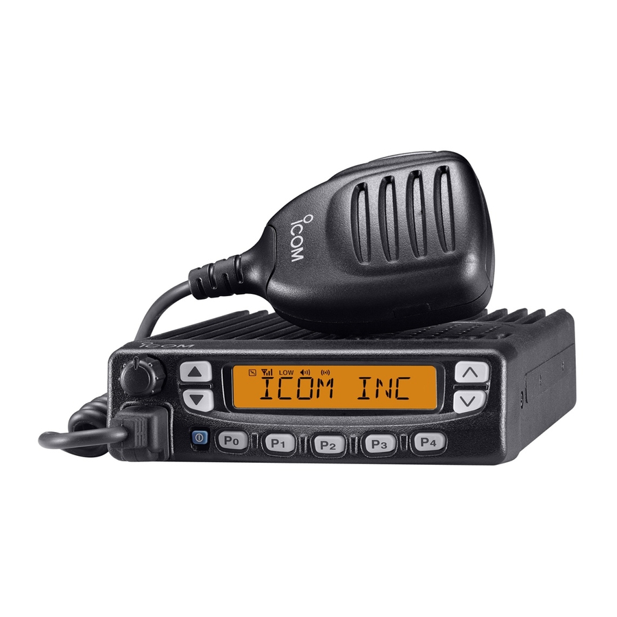
- Page 1 INSTRUCTION MANUAL VHF TRANSCEIVER iF510 UHF TRANSCEIVER iF610...
-
Page 2: Important
Icom, Icom Inc. and the logo are registered trademarks of Icom Incorporated (Japan) in the United States, the United Kingdom, Ger- many, France, Spain, Russia and/or other countries. SmarTrunk II™ is a trademark of SmarTrunk Systems, Inc. -
Page 3: Table Of Contents
I Mounting the transceiver ..............27 Detailed installation notes for Icom mobile transceivers to I Optional unit installation ..............28 be fitted into vehicles are available. Contact your Icom I Antenna ....................30 I Fuse replacement ................30 dealer or distributor. -
Page 4: Panel Description
PANEL DESCRIPTION I Front panel q AF VOLUME CONTROL KNOB e FUNCTION DISPLAY (p. 3) Rotate the knob to adjust the audio output level. Displays a variety of information such as an operating • Minimum audio level is pre-programmed. channel number/name, code, status message. NOTE: The above functions depend on pre-program- w STATUS UP/DOWN KEYS [Y Y ]/[Z Z ] ming. - Page 5 PANEL DESCRIPTION t DEALER-PROGRAMMABLE KEYS [P0] to [P4] y POWER SWITCH [ ] Desired functions can be programmed independently by Push to turn the power ON and OFF. your Dealer. However, the following functions are assigned • The following functions are available at power ON as options: - Automatic scan start as the default for BIIS operation.
-
Page 6: I Function Display
PANEL DESCRIPTION I Function display i BELL INDICATOR qw e Appears/blinks when the specific 5-tone/BIIS code is re- ceived, according to the programming. o CALL CODE MEMORY INDICATOR Appears when the call code memory is selected. !0 SCROLL INDICATOR q TRANSMIT INDICATOR Appears when a received SDM including more than 10 Appears while transmitting. -
Page 7: I Programmable Function Keys
[SCAN A], [SCAN B] keys. SCAN START/STOP KEYS ➥ Push this key to start scanning; and push again to Consult your Icom Dealer or System operator for details con- stop. cerning your transceivers programming. NOTE: Place the microphone on hook to start In the following explanations, programmable function names scanning. - Page 8 PANEL DESCRIPTION [MONI (Audi)] [W/N] WIDE/NARROW KEY MONITOR KEY Push [W/N] to toggle the IF passband width between Activates one of (or two of) the following functions on wide or narrow. each channel independently: [RX SP] EXTERNAL SPEAKER KEY • Push and hold to un-mute the channel (audio is emitted; When external connections are made for the ‘public ad- ‘Audible’...
- Page 9 PANEL DESCRIPTION [RE-DIAL] [TX CODE CH Up], [TX CODE CH Down] DTMF RE-DIAL KEY TX CODE CHANNEL UP/DOWN KEYS Push this key to transmit the last-used DTMF code. Push to select a TX code channel directory. [EMER] EMERGENCY KEY [ID-MR Select] ➥...
- Page 10 PANEL DESCRIPTION [SCRM] SCRAMBLER KEY [OPT OUT] ➥ Push and hold to turn the voice scrambler function OPTION KEYS Control the output signal level of the optional ports in ➥ Push to turn the voice scrambler function OFF. the optional unit connector. NOTE: [DIGITAL] •...
-
Page 11: Operation
OPERATION I Turning power ON I Channel selection q Push [ ] to turn the power ON. Several types of channel selections are available. Methods • A power-up alert tone sounds for about 1 sec. and an opening may differ according to your system set up. message may appear. -
Page 12: I Receiving And Transmitting
OPERATION I Receiving and transmitting D Transmitting notes • Transmit inhibit function RECEIVING: The transceiver has several inhibit functions which restrict q Push [ ] to turn the power ON. transmission under the following conditions: w Push [CH UP] or [CH DN] to select a channel. - The channel is in mute condition (‘Inaudible’... -
Page 13: D Scrambler Function
OPERATION D D Tx code channel selection D D User set mode If the transceiver has a [TX CODE CH UP] or [TX CODE CH User set mode is accessed at power ON and allows you to DN] key, the programmed Tx code channel can be selected set seldom-changed settings. -
Page 14: Biis Operation
BIIS OPERATION I Default setting I Receiving a call D D Individual call The following functions are assigned to each programmable switch as the default. Ask your dealer for details. q When an individual call is received; • Beeps sound. [P0];... -
Page 15: D Displaying The Received Call Record
BIIS OPERATION D D Group call D D Displaying the received call record q When a group call is received; — Queue indication • Beeps sound. The transceiver memorizes the calling station IDs for record. • “ ” appears and the mute is released. Up to 3 calls can be memorized, and the oldest call record is •... -
Page 16: I Transmitting A Call
BIIS OPERATION I Transmitting a call D D Calling back from the queue channel A total of 3 ways for code selection are available— selecting qDuring standby condition, push [DIGITAL (P1)] for 1 sec. to the call code from memory, entering the call code from the keypad and calling back from the queue channel record. -
Page 17: D Direct Code Entry
BIIS OPERATION D D Direct code entry qDuring standby condition, push [TX CODE ENT] to select call code entering condition. Queue memory content is displayed. wSelect the desired code number via [ ] then push [TX CODE ENT]. • Programmable digit number differs according to the setting. •... -
Page 18: I Receiving A Message
BIIS OPERATION I Receiving a message D D Receiving a status message D D Receiving an SDM q When a status message is received; q When a status message is received; • Beeps sound. • Beeps sound. • “ ” appears. •... -
Page 19: D Received Message Selection
BIIS OPERATION D D Received message selection For your information The transceiver memorizes the received messages for When using the optional DTMF microphone, [✱] and [#] keys record. Up to 6 messages for status and SDM, or 192 char- on the microphone function as [Y] and [Z] on the front panel, acter SDM’s can be memorized, and the oldest message is respectively. -
Page 20: I Transmitting A Status
BIIS OPERATION I Transmitting a status D D General D D Select a status from status memory qDuring standby condition, push [DIGITAL (P1)], then push The status message can be selected with the programmed text, and the message text is also displayed on the function ] to select the desired station/group code. -
Page 21: I Transmitting An Sdm
BIIS OPERATION I Transmitting an SDM D D General D D Transmitting an SDM qDuring standby condition, push [DIGITAL (P1)], then push A short data message, SDM, can be input directly (max. 10 characters), and sent to an individual station or group sta- ] to select the desired station/group code. -
Page 22: D Programming An Sdm Memory
BIIS OPERATION D D Programming an SDM memory (optional DTMF microphone required) • Available characters qDuring standby condition, push [DIGITAL (P1)] twice, then Characters push [ ] to select the desired SDM to be edited. w Push [✱] or [#] to enter the message editing condition. (") •... -
Page 23: I Position Data Transmission
BIIS OPERATION I Position data transmission I Printer connection When the optional OPC-822 and a GPS re- When the optional OPC-822 is connected INTERFACE CABLE INTERFACE CABLE ceiver is connected to the transceiver, the position (longitude to the transceiver, a printer can be connected to printed out and latitude) data can be transmitted automatically. -
Page 24: I Auto Emergency Transmission
BIIS OPERATION I Auto emergency transmission I BIIS indication When [EMER (Silent)] is pushed, an emergency signal is au- The following indications are available for the BIIS operation tomatically transmitted for the specified time period. on an MSK channel. : Individual/group call is successful. The status 22 (Emergency) is sent to the selected ID station, : Message (status or SDM) transmission is and the position data is transmitted after the emergency sig-... -
Page 25: I Priority A Channel Selection
BIIS OPERATION I Priority A channel selection When one of the following operations is performed, the trans- ceiver selects the Priority A channel automatically. Priority A is selected when; • Clear down signal is received/transmitted - Set the “Move to PrioA CH” item as “Clear Down.” •... -
Page 26: Smartrunk Ii™ Operation
SmarTrunk II™ OPERATION I SmarTrunk II™ and I SmarTrunk II™ operation conventional modes These features are enabled by a Dealer and may not be available in your system. Contact your Dealer for details. This transceiver is capable of SmarTrunk II™ functions. D D Placing a telephone call The optional UT-105 allows communication in conventional channels or SmarTrunk II™... -
Page 27: Emergency Call
SmarTrunk II™ OPERATION D D Terminating a call D System busy indication After completing a call, push [#] to disconnect (hang up). If all channels are busy, three low beeps sound after you initi- ate a call. Try the call again later. IMPORTANT: If one person in the conversation terminates a call, all participants will be cut off. -
Page 28: Connection And Installation
CONNECTION AND INSTALLATION I Rear panel description and connections Optional speaker q Antenna (SP-22) Red: + NEVER connect to a 24 V battery. This t Optional cable could damage the Black: _ 12 V (OPC-617/822) transceiver. Battery Crimp NOTE: Use the ter- Solder minals for the cable connection. -
Page 29: I Supplied Accessories
CONNECTION AND INSTALLATION I Supplied accessories q ANTENNA CONNECTOR Connects to an antenna. Ask your dealer about antenna selection and optimal antenna locations. w MICROPHONE HANGER Connects the supplied microphone hanger to the vehicle’s ground for the hanger function. e DC POWER RECEPTACLE Connects to a 12 V DC battery. -
Page 30: I Mounting The Transceiver
CONNECTION AND INSTALLATION I Mounting the transceiver r Invert the transceiver 180 degrees clockwise as below. The front panel can be inverted for correct viewing while leav- t Re-attach the Front panel to the transceiver. ing the built-in speaker facing away from the mounting surface. y Tighten the 2 screws. -
Page 31: I Optional Unit Installation
UT-105. IMPORTANT! Detailed installation notes for Icom mobile transceivers to be fitted into vehicles are available. Contact your Icom rAttach the bottom cover and screws to their original posi- dealer or distributor. tion, then connect the DC power cable. - Page 32 CONNECTION AND INSTALLATION D D UT-109/UT-110/UT-117S installation D D OPC-617/822 installation Install the optional unit as below. Either the optional OPC-617 or OPC-822 ACC CABLE INTER can be installed. FACE CABLE q Turn power off, then disconnect the DC power cable. Install the OPC-617 or OPC-822 as shown bellow.
-
Page 33: I Antenna
CONNECTION AND INSTALLATION I Antenna • Connector information A key element in the performance of any communication sys- OPC-617 Pin Assignment tem is an antenna. Ask your Dealer about antennas and the t r e w q q LCD backlit cont. IN y Horn drive cont. -
Page 34: Options
OPTIONS UT-105 SmarTrunk II™ LOGIC BOARD HM-152/HM-152T/HM-148 HAND MICROPHONE For SmarTrunk II™ operation. • HM-152 : Hand microphone. The same as that supplied with the transceiver. UT-117/UT-117S* SmarTrunk 3G™ LOGIC BOARD • HM-152T : DTMF microphone For SmarTrunk 3G™ operation. •... -
Page 35: Doc
Signature vi) EN 300 113-2 v1.1.1 (March 2001) v) EN 300 113 (March 2001) CE Versions of the IC-F510/F610 which display the This warning symbol indicates that this equipment oper- “CE” symbol on the serial number seal, comply with ates in non-harmonised frequency bands and/or may be the essential requirements of the European Radio and subject to licensing conditions in the country of use. - Page 36 < Intended Country of Use > A-6249D-1EU-w Printed in Japan 1-1-32 Kamiminami, Hirano-ku, Osaka 547-0003, Japan 2003–2006 Icom Inc. ©...
Need help?
Do you have a question about the IC-F510 and is the answer not in the manual?
Questions and answers