Icom IC-F610 Instruction Manual
Hide thumbs
Also See for IC-F610:
- Service manual (40 pages) ,
- Instruction manual (36 pages) ,
- Instruction manual (24 pages)
Table of Contents
Advertisement
Quick Links
Advertisement
Table of Contents

Subscribe to Our Youtube Channel
Related Manuals for Icom IC-F610


Summary of Contents for Icom IC-F610
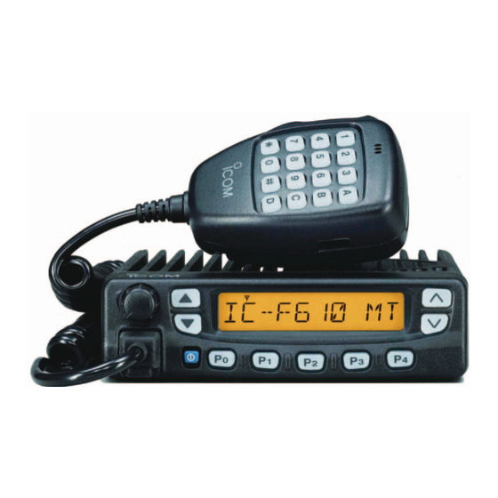
- Page 1 INSTRUCTION MANUAL UHF TRANSCEIVER iF610 iF620...
- Page 2 FCC RF E XPOSURE OMPLIANCE WARNING For compliance with FCC and Industry Canada RF Exposure Requirements, the transmitter antenna installation shall comply with the following two conditions: 1. The transmitter antenna gain shall not exceed 0 dBi 2. The transmitter antenna is required to be located outside of a vehicle and kept at a separation distance of 85 centimeters or more between the transmitter antenna of this device and persons during operation.
-
Page 3: Important
Icom, Icom Inc. and the logo are registered trademarks of supplied microphone only. Other microphones have Icom Incorporated (Japan) in the United states, the United different pin assignments and may damage the transceiver. Kingdom, Germany, France, Spain, Russia and/or other coun- tries. -
Page 4: Table Of Contents
For U.S.A. only I Fuse replacement ............... 18 CAUTION: Changes or modifications to this transceiver, not ex- I Cleaning ................18 pressly approved by Icom Inc., could void your authority to operate OPTIONS ................19 DOC..................20 this transceiver under FCC regulations. -
Page 5: Panel Description
PANEL DESCRIPTION I Front panel qAF volume wLeft rRight eFunction display UP/DOWN keys control knob UP/DOWN keys uMicrophone yPower switch tProgrammable keys [P0] to [P4] connector q AF VOLUME CONTROL KNOB e FUNCTION DISPLAY Turn the knob to adjust the audio output level. Displays variety of information, such as operating channel number/names, 5-tone code, DTMF numbers and audible •... -
Page 6: I Function Display
DEALER-PROGRAMMABLE KEYS [P0] to [P4] q w e Can each be programmed for one of several functions by your Icom dealer. y POWER SWITCH Push to turns the power ON and OFF. • The following functions are available at power ON as options: q TRANSMIT INDICATOR •... -
Page 7: I Programmable Function Keys
] and [ ] programmable function keys. Appears when specified 2/5tone call is received. Consult your Icom Dealer or System operator for details con- o!0 LTR INDICATOR cerning your transceivers programming. Appears when LTR function is selected. In the following explanations, programmable function names !1 SHORT MESSAGE INDICATOR are bracketed, the specific switch used to activate the func-... - Page 8 PANEL DESCRIPTION [Bank] BANK KEY [MONI] MONITOR KEY Select a bank. Activates one of (or two of) the following func- • When the optional UT-105 is installed, push one tions on each channel independently: or more times to select a channel bank for con- •...
- Page 9 PANEL DESCRIPTION • Ask your Dealer or System Operator for the out- [TX CH] TX CODE KEY put power level for each selection. Select a transmit 5-tone code (station code) channel. [ TA ] TALK AROUND KEY Turns the talk around function ON and OFF. [CODE] TX CODE CHANNEL UP/DOWN KEY •...
- Page 10 PANEL DESCRIPTION [ID MR] ID MEMORY READ KEY [SCRM] SCRAMBLER KEY Recalls detected ID codes. • Push and hold to turn the voice scrambler func- • Push this key, then push [ ] for selec- tion ON. tion. • Push to turn the voice scrambler function OFF. •...
-
Page 11: Operation
OPERATION I Turning power ON I Channel selection q Push [K ] to turn the power ON. Several types are available, and the channel selection • A power-up alert tone sounds for about 1 sec. and an opening method may differ according to your system set up. message may appear. -
Page 12: I Receiving And Transmitting
OPERATION I Receiving and transmitting D Transmitting notes RECEIVING: • Transmit inhibit function q Push [K ] to turn the power ON. The transceiver has several lockout/inhibit functions which w Push [ ] or [ ] to select a channel. CH UP CH DN restrict transmission under the following conditions:... -
Page 13: D Tx Code Channel Selection
OPERATION D Tx code channel selection D DTMF transmission If the transceiver has a [ ] key, display can be toggled If the transceiver has a [ ] key, the automatic DTMF TX CH DTMF between the operating channel number (or name) and Tx transmission function is available. - Page 14 OPERATION D User set mode User set mode is accessed at power ON and allows you to set seldom-changed settings. in this case you can “cus- tomize” transceiver operation to suit your preferences and operating style. Entering the user set mode: qWhile pushing and holding [ ] and [ ], push [K...
-
Page 15: Optional Smartrunk Ii™ Operation
OPTIONAL SmarTrunk II™ OPERATION I SmarTrunk II™ and I SmarTrunk II™ operation conventional modes These features are enabled by a Dealer or System Operator and may not be available in your system. Contact your Dealer This transceiver is capable of SmarTrunk II™ functions. for details. - Page 16 OPTIONAL SmarTrunk II™ OPERATION D Terminating a call D System busy indication After completing a call, push [#] to disconnect (hang up). If all channels are busy, three low beeps sound after you initi- ate a call. Try the call again later. IMPORTANT: If one person in the conversation terminates D PTT dispatch operation a call, all participants will be cut off.
-
Page 17: Connection And Maintenance
CONNECTION AND MAINTENANCE I Rear panel and connection Optional speaker q˚Antenna (SP-22) r˚ NEVER connect to red: a 24 V battery. t˚ Optional cable e˚ black: (OPC-617) Supplied DC Battery power cable Crimp Solder Note: Use the terminals for the cable connections. -
Page 18: I Sullpied Accessories
CONNECTION AND MAINTENANCE I Supplied Accessories ⁄ ANTENNA CONNECTOR Connects to an antenna. Ask your Dealer about antenna selection and placement. ¤ MICROPHONE HANGER Connect the supplied microphone hanger to the vehicle’s ground for on/off hook microphone functions. (See p. 2) ‹... -
Page 19: I Mounting The Transceiver
CONNECTION AND MAINTENANCE I Mounting the transceiver The front panel can be inverted for correct viewing while leav- ing the built-in speaker facing away from the mounting surface. t Tight the 2 screws. D Inverting the Front panel NOTE: q Unscrew the 2-side screws. •... -
Page 20: D Mounting The Transceiver
CONNECTION AND MAINTENANCE D Mounting the transceiver The universal mounting bracket supplied with your transceiv- er allows overhead mounting. Please read the following instructions carefully. • Mount the transceiver securely with the 4 supplied screws to a thick surface which can support more than 1.5 Kg. Flat washer Spring washer When using... -
Page 21: I Optional Ut-96/Ut-105 Installation
CONNECTION AND MAINTENANCE I Optional UT-105 and UT-108 I Optional UT-109 /UT-110 in- installation stallation q Turn power OFF, then disconnect the DC power cable. The optional UT-105 and UT-108 units install as follows: w Unscrew the 4 screws, then remove the bottom cover. q Turn power OFF, then disconnect the DC power cable. -
Page 22: I Optional Opc-617 Installation
CONNECTION AND MAINTENANCE I Optional OPC-617 I Antenna installation A key element in the performance of any communication sys- tem is an antenna. Ask your Dealer about antennas and the best places to mount them. I Fuse replacement Two fuses are installed in the supplied DC power cable. If a fuse blows or the transceiver stops functioning, track down the source of the problem, if possible, and replace the dam- aged fuse with a new, rated one. -
Page 23: Options
OPTIONS SP-22 Compact and easy-to-install Input impedance: 4 Ω Max. input power: 5 W HM-100TN DTMF microphone. SM-25 Normal microphone. UT-105 SmarTrunk II™ Logic Board Provides SmarTrunk II™ capabilities. UT-108 DTMF DECODER UNIT Provides pager and code squelch capabilities. UT-109/UT-110 VOICE SCRAMBLER UNIT •... -
Page 24: Doc
Count on us! A-6120H-1EX Printed in Japan 1-1-32 Kamiminami, Hirano-ku, Osaka 547-0003 Japan © 2001 Icom Inc.
Need help?
Do you have a question about the IC-F610 and is the answer not in the manual?
Questions and answers