
Related Manuals for Sony RCP-1500


Summary of Contents for Sony RCP-1500
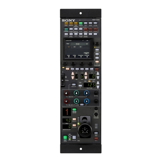
- Page 1 REMOTE CONTROL PANEL RCP-1500 RCP-1501 RCP-1530 OPERATION MANUAL [English] 1st Edition (Revised 1)
- Page 4 This apparatus shall not be used in the residential area. Compliance with this directive implies conformity to the Pour les clients en Europe following European standards: Le fabricant de ce produit est Sony Corporation, 1-7-1 Konan, • EN55103-1: Electromagnetic Interference (Emission) Minato-ku, Tokyo, Japon. • EN55103-2: Electromagnetic Susceptibility (Immunity) Le représentant autorisé...
-
Page 5: Table Of Contents
Table of Contents Precautions..............6 Overview ..............7 Features ................. 7 Examples of System Configurations ....... 8 For the State of California, USA only Supported devices ............10 Perchlorate Material - special handling may apply, See Operating Cameras ............10 www.dtsc.ca.gov/hazardouswaste/perchlorate Names and Functions of Parts ...... -
Page 6: Precautions
About “Memory Stick Duo” ........79 Precautions Inserting a “Memory Stick Duo” ........79 Protecting Saved Data ..........79 Precautions ..............79 Specifications............80 Note on faulty pixels on the LCD panel The LCD panel fitted to this unit is manufactured with high precision technology, giving a functioning pixel ratio of at least 99.99%. -
Page 7: Overview
• Master/subordinate function • The RCP-1500 incorporates an LCD display with direct This function makes changes in conjunction with the color operation switches and a touch panel, which makes it a 1) 2) temperature of the specified camera system. -
Page 8: Examples Of System Configurations
MSU-1000/1500 CCU/CNU REMOTE RCP-1500/1501/1530 CCA-5 cable • The maximum cable length for from a CCU (camera control unit) to an RCP is 200 m. • Up to six systems can be connected to a CNU-700 as standard. In such a case, connect one MSU and one VCS. - Page 9 Connection example for MCS mode Camera heads PoE compatible switching hub RCP-1500 MSU-1000/1500 RCP-1501 LAN straight cable (category 5 or above) RCP-1530 • In MCS mode, be sure to set one of the multiple MSUs as the master. Not to turn off the power or disconnect the cable of the master MSU during operation.
-
Page 10: Supported Devices
Supported devices Operating Cameras This unit supports connection to the following devices. Camera control permissions (panel active, • BVP-E30 series IRIS/MB active, and PARA) • CCU-590/790 series By combining an MSU and RCP, you can operate one camera • HDC-1000(R)/1500(R)/3300(R) series device from multiple control panels, and multiple cameras from •... -
Page 11: Names And Functions Of Parts
(RCP-1500/1501) (page 17) Adjustment block (RCP-1530) (page 24) Adjustment block (RCP-1500) (page 20) Panel control/status display Panel control/status display block (RCP-1500) (page 26) block (RCP-1530) (page 28) RCP-1501 Adjustment block (RCP-1501) (page 22) Panel control/status display block (RCP-1501) (page 27) - Page 12 Camera/panel control block (RCP-1500/1501) a STANDARD button b Test signal output selection buttons This button is for accessing the standard state of the camera. These buttons light when pressed and are for operating the After the standard state is accessed, you can cancel access by test signal generator of the camera to output the pressing the STANDARD button again while it is lit.
- Page 13 Button Description BLACK GAMMA Black gamma function CHARACTER CCU character button Turns ON/OFF character output of the CCU and switches to the next page. When this function is ON, each press of the button switches to the next page (holding the button switches to the last page and stops the function in the OFF state).
- Page 14 Camera/panel control block (RCP-1530) a PARA (parallel control) button c CLOSE (iris close) button This is the PARA function button. It allows you to This button is for closing the iris of the lens connected to the simultaneously control the control panels that are active. camera.
- Page 15 Button Description BLACK GAMMA Black gamma function CHARACTER CCU character button Turns ON/OFF character output of the CCU and switches to the next page. When this function is ON, each press of the button switches to the next page (a long press switches to the last page and stops the function in the OFF state).
- Page 16 Menu operation block RCP-1500/1501 RCP-1530 Menu operation is performed on the LCD. Operation is performed by touching the buttons and tabs that are displayed on the LCD. Use the adjustment knobs to change numbers and select items. To change menus, press a menu button or custom button and then use the buttons in the menu to navigate through the menu.
- Page 17 Function control block (RCP-1500/1501) 1 “Memory Stick Duo” insertion block 2 Scene file control block For details on a “Memory Stick Duo,” see “About “Memory Stick Duo”” (page 79). a SCENE FILE selection buttons and STORE button These buttons are for registering and reading scene files.
- Page 18 a DEG indicator 3 Filter control block This indicator is lit when the shutter display is indicating an angle value. Configure the setting with the switches in Shutter of the Paint menu. b SLS/SHUTTER/ESC indicators The indicator corresponding to the selected function is lit. Select a function in the menu.
- Page 19 Function control block (RCP-1530) e CC (color temperature conversion) filter display 1 Filter control block window This window displays the CC filter that is currently selected. 2 Master gain control block a Standard value indicator a ND filter selection buttons This lights when standard values are set in the Standard Ind These buttons are lit when the RCP has the filter servo control menu.
-
Page 20: Adjustment Block (Rcp-1500)
Adjustment block (RCP-1500) d FLARE (flare balance mode) button 1 White balance/black balance adjustment block This button changes the adjustment mode of the BLACK/ FLARE knobs. The knobs adjust the flare balance when the button is lit, and the black balance when the button is not lit. - Page 21 b IRIS/MB ACTIVE (iris/master black active) button h MASTER BLACK RELATIVE button This button is for the iris and master black control permission. This button changes the manual adjustment mode of the The iris and master black can only be adjusted when this master black control ring.
- Page 22 Adjustment block (RCP-1501) d FLARE (flare balance mode) button 1 White balance/black balance adjustment block This button changes the adjustment mode of the BLACK/ FLARE knobs. The knobs adjust the flare balance when the button is lit, and the black balance when the button is not lit. e DETAIL knob This knob adjusts the detail level.
- Page 23 d Camera number/tally display window i MASTER BLACK knob This window displays an amber number for the camera This knob is for manually adjusting the master black. The controlled by the control panel. setting value is displayed in the master black display window. When a red tally signal is sent to the camera, a black number j EXT (lens extender) indicators is displayed and the background of the number lights in red.
- Page 24 Adjustment block (RCP-1530) d FLARE (flare balance mode) button 1 White balance/black balance adjustment block This button changes the adjustment mode of the BLACK/ FLARE knobs. The knobs adjust the flare balance when the button is lit, and the black balance when the button is not lit. 2 Iris/master control black adjustment block a ABSOLUTE button This button changes the mode for manual adjustment using...
- Page 25 c SENS (iris adjustment range) knob m Master black control ring This knob is for manually adjusting the iris in absolute value This ring is for manually adjusting the master black. The mode. It does not work in relative value mode. setting value is displayed in the master black display window.
- Page 26 Panel control/status display block (RCP-1500) a PANEL ACTIVE button This button is for the control permission. It also serves as a function for preventing unintentional operation because a camera cannot be controlled from this control panel when this button and the PARA button are not lit.
- Page 27 Panel control/status display block (RCP-1501) a PANEL ACTIVE button This button is for the control permission. It also serves as a function for preventing unintentional operation because a camera cannot be controlled from this control panel when this button and the PARA button are not lit. b CALL button This button is for communication.
- Page 28 Panel control/status display block (RCP-1530) a PANEL ACTIVE button This button is for the control permission. It also serves as a function for preventing unintentional operation because a camera cannot be controlled from this control panel when this button and the PARA button are not lit. b CALL button This button is for communication.
-
Page 29: Connector Panel
This is for connecting to the RCP/CNU connector of the CCU or the RCP connector of the CNU. c AUX REMOTE (auxiliary remote) connector (8-pin multi-connector, female) (RCP-1500/1501 only) This is a spare connector. d EXT I/O connector (D-sub 9-pin, female) This is used for external interface connections. -
Page 30: Installation
Setting the Status Screen Display Installation You can disable the Status screen that is displayed when no MENU buttons are lit. With the Status screen disabled, a blank screen appears if no For details on menu operations, see page 53. MENU buttons are lit. -
Page 31: Setting The Clock
Set the date. Setting the Clock [Date] 1 Press and highlight The control panel has an internal clock for recording the date and time at which reference files and scene files are saved to Date/Time Exit a “Memory Stick Duo.” Use the following procedure to set the clock. -
Page 32: Setting The Lan Connection
LAN I/F: Sets LAN I/F to OFF. Setting the LAN Connection Negotiation AUTO: The connection settings for the target equipment are configured automatically. Use AUTO When connecting using a LAN cable, set the LAN I/F as only when the target equipment also supports the Auto follows: Negotiation function. -
Page 33: Setting Bridge Mode
[CNS] [CNS] Press Press The CNS screen appears. The CNS screen appears. Exit Exit Legacy Legacy Mode:Semi-Auto Mode:Semi-Auto Bridge Edit Bridge Edit Target: Cancel Target: Cancel 192.168.0.1 192.168.0.1 Mode:Master Mode:Master Edit Edit Master: Master: 192.168.0.1 192.168.0.1 RCP No. 96 RCP No. 96 [LEGACY] [Bridge] Press... -
Page 34: Setting Multi-Camera System (Mcs) Mode
[TCP/IP] [Network] 1 Press Press The TCP/IP screen appears. The Network screen appears. Network TCP/IP Exit Exit IP Address Network LAN I/F TCP/IP Info Subnet Mask Default GW Enter Cancel 2 Set the IP address, subnet mask, and default gateway. [CNS] Press Press the corresponding input field, and then use the... -
Page 35: Changing The Output Destination For Previews
[Mode] 1 Turn the adjustment knob on the far left to change the Press RCP number. The RCP Mode screen appears. RCP Mode Exit Note If an RCP number is duplicated, the equipment will not Screen Matrix Extend function normally. Be sure to set a number that will not be PIX/WF Saver Gate... -
Page 36: Settings
Call: Sets the sound played when call signals are “Sound” and then press the SELECT knob. received. Touch: Sets the sound played when the LCD/touch panel RCP-1500/1501 is touched. SW: Sets the sound played when the buttons are pressed. RE: Sets the sound played when the adjustment knobs... -
Page 37: To Set The Brightness Of The Leds
SELECT knob if you turn the SELECT knob to select To adjust the LCD “LED” and then press the SELECT knob. You can adjust the brightness of the LCD of the menu RCP-1500/1501 operation block. Display the RCP Config screen. (page 51) Display/Sound... - Page 38 RCP-1500/1501 Turn the SELECT knob to select “EL.” The EL screen appears. Display/Sound Exit The EL screen can also be displayed after you press the SELECT knob if you turn the SELECT knob to select “EL” Clear and then press the SELECT knob.
-
Page 39: To Change The Sensitivity Of The Adjustment Knobs
To change the sensitivity of the adjustment To adjust the sensitivity of the DETAIL and assignable knobs (RCP-1500/1501 only) knobs You can change the sensitivity of the WHITE, BLACK/FLARE, [Detail/Assign] Press the tab. DETAIL, assignable, IRIS, and MASTER BLACK adjustment knobs for when they are used in relative value mode. -
Page 40: To Perform Rpn Correction
[Mode] Press Enter engineer mode. (page 52) The Mode screen appears. Security Exit RCP Mode Exit Code Page Item Screen Matrix Extend PIX/WF Permission Permission Change Saver Gate Call Panel Status Preview Active Display Engeneer Preset Mode [Exit] Press to return to the Category Select screen. [Screen Saver] Press Category Select... -
Page 41: Setting Security Restrictions
Select the cursor type displayed on the monitor. Turn the adjustment knob on the far right to correct [H Cursor] : Press this to light the button and turn the the defect on the monitor. horizontal cursor ON. Turning the adjustment knob right increases the [V Cursor] : Press this to light the button and turn the brightness level, and turning it left decreases the... -
Page 42: To Protect Operations With A Security Code
To enable security code protection Under the default settings, the security code is disabled. Use the following procedure to enable the security code. For RCP-1500/1501, turn on the control panel while View holding down the PARA, MASTER, and CUSTOM Full Lock Mode PAINT buttons. - Page 43 [Code Change] The numeric keypad appears. Press The numeric keypad and new security code (Code No.) Security Exit input field appear. Engineer Protection Security Exit Code No: Engineer Mode Code No: Cancel Cancel Use the numeric keypad to enter “0359,” and then [OK] press The Engineer Protection screen appears.
-
Page 44: Operation Settings
3. [PIX/WF] Press [Code Enable] • Press to turn the button light off (security The PIX/WF screen appears. code protection is disabled). RCP-1500/1530 [Code Delete] • Press to light the button (the security code is deleted). PIX/WF Exit Operation Settings... -
Page 45: Customization
[Customize] Set the PIX/WF operations Press The following settings can be configured. The Customize screen appears. PIX/WF Synchro RCP Customize Exit Turn ON/OFF linking of output from the PIX2 OUTPUT and WF2 OUTPUT connectors to RGB switching on the Menu Custom adjustment display. -
Page 46: To Assign Functions To Assignable Adjustment Knobs
[Customize] Repeat steps 6 to 8 if you want to assign functions to Press multiple buttons. The Customize screen appears. RCP Customize Exit [Save] Press The confirmation message screen appears. Menu Custom Customize Customize Menu SW Customize [Save] Press The function assignments of assignable buttons are Standard saved. -
Page 47: To Set The Custom Paint Menu
[Menu Customize] To reset the function assignments of assignable Press adjustment knobs to their default settings The Menu Customize screen appears. [Default All] Press Menu Customize The confirmation message screen appears. Exit Custom Paint Menu Delete Save [OK] Press 1 Detail 2 Skin Detail The function assignments of assignable adjustment 3 Gamma... -
Page 48: To Assign Menus To Custom Buttons
[Customize] To delete a paint menu item from the custom paint Press menu The Customize screen appears. RCP Customize Exit Turn the SELECT knob to select the paint menu item to delete in the top list. Menu Custom Customize Customize Menu SW Customize [Delete]... -
Page 49: Saving And Initializing Settings
Repeat steps 6 to 8 if you want to assign functions to Display the RCP Config screen. multiple buttons. RCP Config Exit [Save] Press Display The confirmation message screen appears. Customize Mode /Sound Setting [Save] Press Date Infor- Network Security /Time mation The function assignments of custom buttons are saved. - Page 50 [Store] [OK] Press Press The screen changes as follows. The RCP configuration menu settings are all reset to their default settings. Menu Customize Exit File Store Recall Delete Number Date Time 09/10/10 14:30 RCP-1501 09/12/31 16:25 RCP-1501 Input file no : Enter RCP =>...
-
Page 51: Menus
Set or adjust the item. RCP-1500/1501 • Turn the adjustment knob (or press the button) in accordance with the setting and adjustment item (parameter) to adjust the setting value (select a setting). - Page 52 [RCP] [Security] Press Press The RCP screen appears. The Security screen appears. RCP Config Security Exit Exit Display Mode /Sound Date Infor- Security /Time mation Engeneer Mode [Engineer Mode] Press to light the button. To enter engineer mode The items that were hidden appear. Some settings of the control panel have their functions restricted and are not displayed to prevent unintentional Security...
-
Page 53: Menu Tree
Menu Tree Paint File Config Lens White Ref File Camera Ref Store Auto Iris Settings Ref Transfer Flare Color Temp Adjusting V Mod Saw Customize Black Scene File ALAC Flare Display/Sound Store/Recall Detail Sound Scene Transfer Call Phase Adjusting Touch Lens File Skin DTL Lens Store... -
Page 54: Status Screen
Status Screen Status screen of RCP-1500/1501 Status screen of RCP-1530 White White Detail Black Black Blk Gamma Master 1 Displays the value adjusted with the white balance/black 1 Displays the value adjusted with the white balance/black balance adjustment block of the control panel. When the balance adjustment block of the control panel. - Page 55 You can press items with a red frame around them to clear their values one by one. If you press c, the values for all of the items with a red frame around them will be cleared. [Clear] To cancel clearing items, press again.
- Page 56 Menu items The mark in the “Control Item” column indicates an item that is assigned to a paint adjustment knob. Paint menu Switch Control item Description Menu Submenu White Corrects the color reproduction of the camera to match the color temperature of the light source shining on the subject.
- Page 57 Paint menu Switch Control item Description Menu Submenu Detail Corrects the contour. Disables the detail function. This is the first page of detail adjustment. Level Adjusts the contour correction level. Adjusting this in the plus direction makes pictures sharp, and adjusting this in the minus direction makes pictures soft.
- Page 58 Paint menu Switch Control item Description Menu Submenu Skin DTL Allows adjustment of the contour correction level of the set color area. For example, allows you to make the faces of people appear shiny. Enables the Skin DTL function. Allows up to three channels to be adjusted separately.
- Page 59 Paint menu Switch Control item Description Menu Submenu Skin DTL 3 Sets the third channel of Skin DTL. Skin DTL 3 Enables Skin DTL of this channel. When this channel is enabled, the ON mark appears on the very left of the tab. Level This is the contour correction value within the color area that is set with Phase or Width.
- Page 60 Paint menu Switch Control item Description Menu Submenu Preset Matrix Selects the matrix provided for the camera in advance. When Preset Matrix is enabled, the ON mark appears on the very left of the tab. Enables Preset Matrix. Preset Matrix Selects the matrix provided for the camera in advance.
- Page 61 Paint menu Switch Control item Description Menu Submenu Shutter Controls the exposure time of the image pickup device. Shutter Selects and sets the shutter mode. Slow Shutter Slow Shutter Shoots with the frequency from the frame frequency of the capture image format (unit: number of frames).
- Page 62 Paint menu Switch Control item Description Menu Submenu Flicker Reduction This is a function for Super Motion. It allows you to reduce flickering on the screen caused by the relationship between temporal fluctuations of the light source and the frame frequency of the camera. Enables the Flicker Reduction function.
-
Page 63: File Menu
File Menu Screen display example (when “Ref File” is selected in the File menu, and then “Ref Transfer” is selected) Ref Transfer Exit Date Time Enter a Press this to return to the previous menu screen. c This displays a list of reference files that can be transferred. When there are multiple reference files, turn the SELECT b Press a button to select the transfer destination and source. -
Page 64: Maintenance Menu
Maintenance Menu Screen display example (when “Camera” is selected in the Maintenance menu, and then “Black Shading” is selected) Camera Exit Black Shading Clear Auto B Shading H Saw H Para V Saw V Para a This indicates the page number/total number of pages. d Press this to clear the setting items. - Page 65 Maintenance menu Submenu Switch Control item Description Menu Secondary menu Auto B Shading This is the Auto Black Shading. It automatically adjusts each of the RGB, HV, and SAW/PARA parameters. Auto adjustment may be additionally performed with 2D Black Shading depending on the camera.
- Page 66 Maintenance menu Submenu Switch Control item Description Menu Secondary menu Auto W Shading This is the Auto White Shading. It automatically adjusts each of the RGB, HV, and SAW/PARA parameters. Auto adjustment may be additionally performed with 3D White Shading depending on the camera.
- Page 67 Maintenance menu Submenu Switch Control item Description Menu Secondary menu Multi Matrix Allows you to change color reproduction for each hue divided into 16. Phase Selects the hue to adjust. Changes the hue of colors within the hue range selected with Phase.
- Page 68 Maintenance menu Submenu Switch Control item Description Menu Secondary menu These are the maintenance items related to the CCU. Phase When a synchronization signal is input to the CCU, this allows you to set the phase in relation to that signal. Sets the phase of H.
- Page 69 Maintenance menu Submenu Switch Control item Description Menu Secondary menu This is the second page of SD Detail adjustment. H/V Ratio Adjusts the horizontal and vertical ratio of contour correction. Frequency Adjusts the center frequency of contour correction. Detail Comb Reduces cross color noise by applying the comb filter to contour correction signals.
- Page 70 Maintenance menu Submenu Switch Control item Description Menu Secondary menu Interpolation Selects the filter for the down converter. Each of the frequency characteristics differ. Selects the filter for the horizontal direction. Selects the filter for the vertical direction. Cross Color Reduction Reduces the cross color of VBS output.
-
Page 71: Config Menu
Config Menu Screen display example (when “Camera” (Camera Config) is selected in the Config menu) Camera Config Exit White Gamma RGB Auto White Shading mode RB Only 16:9 Chroma Filter Crop Wide a This indicates the page number/total number of pages. d Press either of the buttons to select a mode. - Page 72 Config menu Item Option Function Menu V Detail Creation Mode Select the generation method for V Detail. RGB Nam Uses the V Detail generated from each of the R, G, and B channels that has the largest amplitude. This increases resolution sensitivity, but S/N sensitivity may deteriorate.
- Page 73 RCP menu items Menu Item Option Function Customize – Menu Customize Changes the custom paint configuration. This can only be set when in engineer mode. – SW Customize Assigns functions to spare switches. This can only be set when in engineer mode.
- Page 74 Menu Secondary Submenu Switch Control Description menu item Adjusts the LCD. Bright Adjusts the brightness of the LCD. Adjusts the backlight for illuminating the function names. Turns off the backlight. Light Detect Turns off the backlight in response to the surrounding brightness. Detect Sets the brightness for turning off the backlight.
- Page 75 Menu Item Option Function Security Page Permission Full Lock Locks all menu screens. View Mode Locks the menu screens. However, the menus can be viewed. Full Paint Enables the menus such as Paint, Maintenance, and File. Item Permission Ref File Enable Enables the operation of reference files.
- Page 76 To set the return input settings To control the CCU menu [Return Settings] [CCU Menu Control] Select in the CONFIG menu to set the Select in the CONFIG menu to remotely formats of return signals from the CCU. control the menu displayed for image output of the CCU from this control panel.
-
Page 77: Multi Menu
Multi Menu Multi Exit Master Subordinate a Press this to return to the previous menu screen. Menu items Item Function Master Sets this unit to master mode. Subordinate Sets this unit to subordinate mode. Function Menu Screen display example (when PIX/WF is selected) Function Exit PIX/WF... -
Page 78: Scene Menu
Scene Menu Screen display example (when connected to the cameras of the 32 scene files) Scene Exit Prev Next Store Scene Scene [Store] a This indicates the page number/total number of pages. d Press and then press the desired scene file When this indication is displayed, you can turn the SELECT number to register the file. - Page 79 • To prevent data loss, make backups of data frequently. In no Confirm the orientation of the “Memory Stick Duo” before event will Sony be liable for any loss of data. inserting it. If there is some resistance when you insert it or it •...
-
Page 80: Specifications
10.5 V to 30 V DC Power consumption 5 °C to 40 °C (41 °F to 104 °F) Operating temperature Weight RCP-1500/1501: 1.8 kg (3 lb. 15 oz.) RCP-1530: 1.6 kg (3 lb. 8 oz.) External dimensions Unit: mm (inches) RCP-1500 125 (5) - Page 81 Always verify that the unit is operating properly before use. 80 (3 67 (2 SONY WILL NOT BE LIABLE FOR DAMAGES OF ANY KIND INCLUDING, BUT NOT LIMITED TO, COMPENSATION OR REIMBURSEMENT ON ACCOUNT OF THE LOSS OF PRESENT OR PROSPECTIVE...
- Page 82 Specifications...
- Page 83 The material contained in this manual consists of information that is the property of Sony Corporation and is intended solely for use by the purchasers of the equipment described in this manual. Sony Corporation expressly prohibits the duplication of any...
- Page 84 Sony Corporation RCP-1500 (SY) Printed in Belgium RCP-1501 (SY) 2010.08 08 RCP-1530 (SY) © 2010 4-169-285-02 (1)
Need help?
Do you have a question about the RCP-1500 and is the answer not in the manual?
Questions and answers