Sony RCP-750 Operation Manual
Remote control panel
Hide thumbs
Also See for RCP-750:
- Operating instructions manual (149 pages) ,
- Operation manual (64 pages) ,
- Maintenance manual (120 pages)

Subscribe to Our Youtube Channel
Related Manuals for Sony RCP-750


Summary of Contents for Sony RCP-750
- Page 1 REMOTE CONTROL PANEL RCP-750/751 OPERATION MANUAL [Japanese/English] 1st Edition (Revised 1)
- Page 3 2(J) ........................3(J) ........................4(J) ......................... 5(J) ....................12(J) ..................13(J) ..................23(J) ........................ 26(J) ....................28(J) ........................ 1 (J)
- Page 4 • 2 (J)
- Page 5 AUX REMOTE CCU/CNU REMOTE (CCA 3 (J)
- Page 6 ECS/ 3.5 LCD 4 (J)
- Page 7 RCP-750 PARA MASTER SLAVE CAM PW TEST BARS CLOSE AUTO SETUP STANDARD AUTO SETUP CHAR SKIN DTL LEVEL START/ STANDARD WHITE BLACK ACTER AUTO HUE BREAK /CCU 5600K AUTO SKIN BLACK KNEE DETAIL GATE GAMMA ON/OFF PAINT 1 PAINT 2...
- Page 8 5600K AUTO KNEE SKIN DETAIL DTL GATE PARA MASTER SLAVE BLACK GAMMA CHARACTER PARA ON 1 ON 2 ON n MASTER SLAVE WHITE STANDARD BLACK/FLARE /CCU ON/OFF CHAR ACTER 5600K AUTO SKIN BLACK KNEE DETAIL GATE GAMMA 6 (J)
- Page 9 ALARM CLOSE CALL AUTO SETUP AUTO SETUP SKIN DTL LEVEL START/ WHITE BLACK AUTO HUE BREAK PANEL ACTIVE SKIN DTL AUTO HUE LEVEL START/BREAK CAM PW TEST BARS CLOSE CAM PW WHITE BLACK TEST BARS 7 (J)
- Page 10 PAINT 1 PAINT 2 PAINT 3 SCENE MAINTE FUNCTION NANCE DETAIL MEMORY STICK MODE PAINT 1/2/3 SCENE MAINTENANCE FUNCTION 8 (J)
- Page 11 RCP-750 IRIS/MB ACTIVE AUTO IRIS/MB ACTIVE MASTER BLACK SENS MASTER SENS BLACK AUTO MASTER BLACK COARSE RELATIVE RELATIVE RELATIVE CLOSE OPEN COARSE IRIS IRIS IRIS RELATIVE MASTER BLACK AUTO MASTER BLACK RELATIVE IRIS/MB ACTIVE SENS 9 (J)
- Page 12 COARSE IRIS RELATIVE IRIS (RELATIVE (RELATIVE RCP-751 IRIS RELATIVE MASTER BLACK MASTER BLACK SENS MASTER COARSE BLACK RELATIVE SENS OPEN CLOSE COARSE IRIS/MB ACTIVE AUTO IRIS/MB ACTIVE IRIS IRIS AUTO MASTER BLACK MASTER BLACK 10 (J)
- Page 13 IRIS/MB ACTIVE AUTO IRIS RELATIVE CCU/CNU REMOTE AUX REMOTE EXT I/O REMOTE EXT I/O CCU/CNU SENS CCU/CNU REMOTE COARSE AUX REMOTE EXT I/O IRIS 11 (J)
- Page 14 12 (J)
- Page 15 PAINT 1 PAINT 2 PAINT 3 SCENE MAINTE FUNCTION NANCE • • [OK] • • • • PAINT 1/2/3 SCENE MAINTENANCE FUNCTION 13 (J)
- Page 16 Status Shutter M. Gain Gamma 0.45 White Detail Black WHITE BLACK/FLARE DETAIL Detail Black SD Detail Flare 1 / 6 Clear (1 6) White Black Flare Gamma 14 (J)
- Page 17 White 1 / 6 Clear Clear White Black Flare Gamma WF/PIX White Select ON/OFF Clear Skin Detail 2 / 6 Clear Detail Skin Black Detail Gamma WF/PIX Skin Detail Select Skin DTL 1 Level Phase Width WF/PIX Skin Detail Select Skin DTL 2 Level...
- Page 18 [WF/PIX Select] R/G/B RGB R WF/PIX Monitor Select SEQ WF WF/PIX Select Store Store Scene File Recall Store 16 (J)
- Page 19 Operation Opera- tion Filter Ctrl Filter Gamma Ctrl 0.05 0.45 Master Shutter Gain 30.00 Opera- tion S-Skin Low Key Knee 1 / 2 Mono Black Knee Knee Gamma Aperture Auto Skin Detail 5600K Knee Detail Gate ON/OFF 17 (J)
- Page 20 18 (J)
- Page 21 19 (J)
- Page 22 20 (J)
- Page 23 –> –> –> –> 21 (J)
- Page 24 22 (J)
- Page 25 RCP-750/751 RCP Config. Menu Exit Date Infor- Adjusting Setting Time mation /LCD [LCD] PAINT 1 PAINT 2 PAINT 3 SCENE MAINTE FUNCTION NANCE Maintenance Menu Adjusting File [Date/Time] Memory Config Stick Date Time Set Menu Exit 2001/11/17 (Sat) 22 : 12 : 31...
- Page 26 Clear Exit Buzzer [Set] Volume Bright [Set] [Cancel] [Time] [Buzzer Volume] Date Time Setting Exit 2001/11/17 (Sat) 22 : 12 : 31 Clear Exit Date Time Cancel Buzzer Hour Minute Second Volume Bright Buzzer Volume Call Touch Buzzer Click Click Call Touch Switch...
- Page 27 Exit Rotary Encoder Setting [RCP Adjusting] BLACK/FLARE DETAIL Detail Black Flare ( HD ) Detail [LED Bright] [Black] [Flare] [Detail$HD%] Clear Exit [SD Detail] Buzzer Volume Bright Bright [Exit] Switch Tally Other Master Switch Tally [LCD] Other Master Clear Exit [Exit] LCD Brightness /Contrast...
- Page 28 26 (J)
- Page 29 • • • • • • • • • • • • 27 (J)
- Page 30 28 (J)
- Page 31 English For the customers in Europe WARNING This product with the CE marking complies with the EMC To prevent fire or shock hazard, do not expose the unit to Directive (89/336/EEC) issued by the Commission of the rain or moisture. European Community.
-
Page 32: Table Of Contents
Basic Configuration of Menu Display .......... 13(E) Menu Items ..................17(E) Initial Settings ..................22(E) Setting the Operating Conditions of the RCP-750/751 ....22(E) Setting the Built-in Clock .............. 22(E) Adjusting the Buzzer Sound ............23(E) Adjusting the Brightness of the LEDs ........... 24(E) Changing the Functions of the Rotary Encoders ...... -
Page 33: Overview
The RCP-750 and RCP-751 are completely identical in selected. their functions except with respect to the iris and master black adjustments. For the iris and master black adjustments, the RCP-750 Signal transmission via a digital line uses a joystick type control while the RCP-751 uses rotary knobs. -
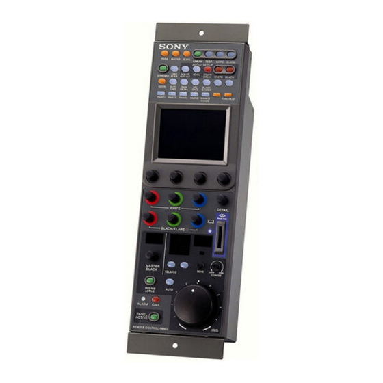
Page 34: Locations And Functions Of Parts
Locations and Functions of Parts Operation Panel RCP-750 1 Control select block 0 Power and output signal select block PARA MASTER SLAVE CAM PW TEST BARS CLOSE AUTO SETUP 2 STANDARD button qa AUTO SETUP block CHAR SKIN DTL LEVEL... - Page 35 1 Control select block 5600K: 5600K electric color temperature conversion function AUTO KNEE: Auto knee function. When this button is lit (ON), the knee point is automatically adjusted according to the light content of the picture. SKIN DETAIL: Skin tone detail function DTL GATE: Skin tone detail gate function.
- Page 36 Locations and Functions of Parts 6 Camera number/tally indication window B Signal output select buttons The number of the camera being controlled from this Press and light up one of these buttons to activate the panel is displayed in orange. test signal generator of the video camera and send the When a red tally signal is sent to the camera, the respective signals.
- Page 37 D BLACK (black balance) button B LCD/touch panel Press to automatically adjust the black balance and Normally displays the statuses (see page 13(E)) black set. When you press a MODE button, the corresponding The button lights during adjustment and goes dark menu is displayed to permit you to adjust the displayed when adjustment is completed.
- Page 38 Locations and Functions of Parts Iris/master black control block (RCP-750) 3 IRIS/MB ACTIVE button 4 AUTO button 5 f-number display 6 EXT indicator IRIS/MB ACTIVE 1 MASTER BLACK display 7 SENS control knob MASTER SENS BLACK AUTO 2 MASTER BLACK RELATIVE...
- Page 39 (RELATIVE button not lit) IRIS lever Adjusts the iris with Adjusts the iris 0 IRIS control lever (RCP-750)/ relative values within within the variable When the AUTO button is not lit, you can adjust the IRIS control 1/4 of the total range range set by the iris manually by moving the lever.
-
Page 40: Connector Panel
Locations and Functions of Parts 4 IRIS RELATIVE (iris relative) button qa AUTO button When the IRIS/MB ACTIVE button is lit, the iris Press and light the button to automatically adjust the adjustment mode can be selected with this button. iris according to the amount of input light. -
Page 41: Mounting On A Console
Mounting on a Console The RCP-750/751 can be mounted on a console as shown below: 11(E) -
Page 42: Menu Configuration And Basic Menu Operations
Menu Configuration and Basic Menu Operations The RCP-750/751 provides menu operations for Select the item to be adjusted. various functions such as adjustments of system equipment. Press the button that shows the name of the item on the menu to obtain the corresponding adjustment display or operation area. -
Page 43: Basic Configuration Of Menu Display
Basic Configuration of Menu Display Status display When you do not select any of the MODE buttons (PAINT 1, PAINT 2, PAINT 3, SCENE, MAINTENANCE, FUNCTION) of the menu operation block (all unlit), the LCD shows the following status display: On the status display, each item is Status only displayed. - Page 44 Menu Configuration and Basic Menu Operations Adjustment display (Paint menu) When you select an item on the initial display of the Paint menu, the lower half of the panel becomes the adjustment display for the selected item. Example: when you select “White” from the initial display The name of the item selected on the 1 / 6 Clear...
- Page 45 Monitor output set display (Expansion menu) [WF/PIX Select] When you press on an adjustment display of the Paint menu, the upper half of the panel becomes the monitor output setting display. R/G/B: To independently select the R, WF/PIX Monitor Select G, or B signal.
- Page 46 Menu Configuration and Basic Menu Operations Function menu displays When you press and light the FUNCTION button of the menu operation block, the scene file operation menu display is obtained. When “Operation” is selected Press v or V to select the desired filter. The number of ND and CC filters you may select depends on the camera.
-
Page 47: Menu Items
Menu Items The “Control items” marked with are those assigned to the control knobs. The other items are operated on the menu display. Paint menu Paint menu consists of pages 1 to 6. You can select page 1 through 3 directly by pressing the MODE buttons, PAINT 1, PAINT 2, or PAINT 3. - Page 48 Menu Configuration and Basic Menu Operations Page Menu Submenu Control item Function Paint 3 Knee Point R/G/B/Master Adjusts the knee point. Knee Off Turns the knee ON/OFF. Knee Slope R/G/B/Master Adjusts the knee slope. Knee Off Turns the knee ON/OFF. Matrix Matrix 1 R-G/G-B/B-R...
- Page 49 Page Menu Submenu Control item Function Paint 5 Detail 2 H/V Ratio Adjusts the HD detail H/V ratio. (Continued) Frequency Adjusts the HD detail boost frequency. Mix Ratio Adjusts the HD detail mix ratio. Comb Adjusts the HD detail comb. Detail Off Turns the HD detail ON/OFF.
- Page 50 Menu Configuration and Basic Menu Operations Maintenance menu Menu 2ndary menu Submenu Control item Function Adjusting Black Shading R/G/B H Saw/H Para/V Saw/V Para Adjusts the black shading. Auto B Shading Executes the auto black shading. Blk Shd OFF Turns the black shading ON/OFF. White Shading R/G/B H Saw/H Para/V Saw/V Para...
- Page 51 Menu 2ndary menu Submenu Control item Function LCD Brightness/Contrast Bright Adjusts the brightness of the LCD of this panel. Contrast Adjusts the contrast of the LCD of this panel. Memory Stick Memory Stick Format Formats a Memory Stick. Function menu Menu Submenu Control item...
-
Page 52: Initial Settings
Time mation By using the RCP Configuration menu or LCD setting display, you can set the built-in clock of the RCP-750/ 751 and adjust various conditions of the RCP-750/751, such as the sound volume of the warning buzzer and the brightness of the indicators and LCD. -
Page 53: Adjusting The Buzzer Sound
(Master). Adjusting the Buzzer Sound To turn on/off the buzzers independently A buzzer sounds on the RCP-750/751 when it receives Press the corresponding button. When it is lit, the call signal or a panel control is operated. -
Page 54: Adjusting The Brightness Of The Leds
Initial Settings [RE Setting] Press on the RCP Configuration Adjusting the Brightness of the menu to obtain the Rotary Encoder Setting display. LEDs Exit You can adjust the brightness of the LEDs of the panel buttons and camera number/tally indication window. To adjust the brightness, proceed as follows. -
Page 55: Memory Sticks
Memory Sticks Using a Memory Stick Notes on Memory Stick When a Memory Stick is inserted in the panel, the file On Memory Stick data can be stored on the Memory Stick, which enables you to share data among RCPs. Memory Stick is a new compact, portable and versatile IC recording medium with a data capacity that exceeds that of a floppy disk. - Page 56 RCP-750/751 may not be used with som cameras. To exchagne the setting data with a camera via a Memory Stick, be sure to use Memory Sticks of a size that can be used with both the RCP-750/751 and the camera. Memory Stick and are the trademarks of Sony Corporation.
-
Page 57: Specifications
× 14 × 5 inches) RCP-751: 102 × 354 × 86.5 mm × 14 × 3 inches) Mass RCP-750: 1.5 kg (3 lb 5 oz) RCP-751: 1.3 kg (2 lb 14 oz) Inputs/outputs REMOTE CCU/CNU: 8-pin multiconnector (1) AUX: 8-pin multiconnector (1) - Page 59 The material contained in this manual consists of information that is the property of Sony Corporation and is intended solely for use by the purchasers of the equipment described in this manual. Sony Corporation expressly prohibits the duplication of any...
- Page 60 Sony Corporation Printed in Belguim B&P Company RCP-750/751(SY) 2002.03.08 3-206-914-02(1) 2002...
Need help?
Do you have a question about the RCP-750 and is the answer not in the manual?
Questions and answers