Table of Contents
Advertisement
Quick Links
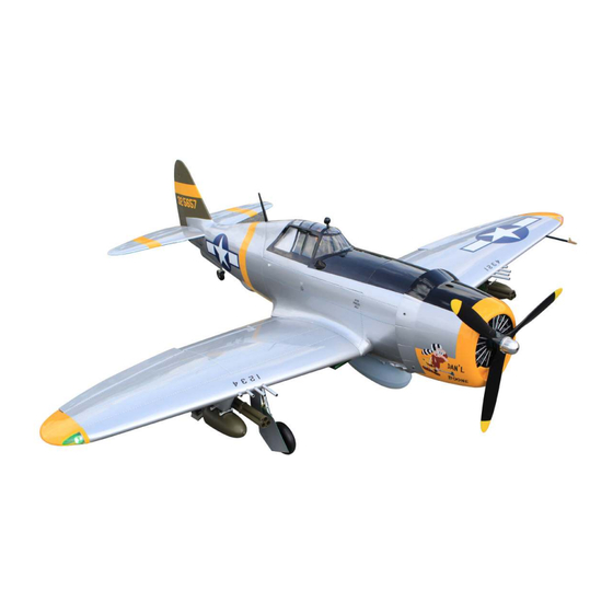
Code : SEA 306N
ASSEMBLY MANUAL
Speciications:
Wingspan-------------------- 81.0 in----------------------- 206.0 cm.
Wing area-------------------- 1200.3 sq.in---------------- 77.4 sq.dm.
Weight------------------------ 26.0 lbs---------------------- 11.8 kg.
Length------------------------ 67.6 in----------------------- 171.6 cm.
Engine------------------------ 55 - 60cc.
Motor size--------------- Motor 360/ 6000watt/ ESC 160A - 200A/ Lipo 12s.
Electric propeller ----------- 24x10 - 25x12.
Radio-------------------------- 6 - 9 channels with 10 servos.
1
Advertisement
Table of Contents

Related Manuals for Seagull Models SEA 306N


Summary of Contents for Seagull Models SEA 306N
- Page 1 Code : SEA 306N ASSEMBLY MANUAL Speciications: Wingspan-------------------- 81.0 in----------------------- 206.0 cm. Wing area-------------------- 1200.3 sq.in---------------- 77.4 sq.dm. Weight------------------------ 26.0 lbs---------------------- 11.8 kg. Length------------------------ 67.6 in----------------------- 171.6 cm. Engine------------------------ 55 - 60cc. Motor size--------------- Motor 360/ 6000watt/ ESC 160A - 200A/ Lipo 12s.
-
Page 2: Kit Contents
Instruction Manual. Giant P-47 55-60cc Gas/EP ARF, 81” INTRODUCTION hank you for choosing the Giant P-47 55-60cc Gas/EP ARF, 81” ARTF by SG MODELS . he Giant P-47 55-60cc Gas/EP ARF, 81” was designed with the intermediate/advanced sport lyer in mind. It is a semi scale airplane which is easy to ly and quick to assem- ble. -
Page 3: Additional Items Required
KIT CONTENTS WING TIP BULBS SEA306N Giant P-47 55-60cc Gas/EP Please see below pictures. ARF, 81” 1. Fuselage 2. Wing set (2) 3. Tail set (2) 4. Canopy 5. Cowling 6. Wing tube 7. Pilot 8. Fuel tank 9. Pushrod set Use Lipo 2s - 3s for led bulbs 10. - Page 4 Instruction Manual. Giant P-47 55-60cc Gas/EP ARF, 81” C/A glue Epoxy INSTALL THE AILERONS CONTROL HORN Locate the aileron control horns. he taller control horn is used for the ailerons, and the shorter horn for the laps. Fiberglass control horn Use sandpaper to scuf the bottom of the aileron and lap control horns.
- Page 5 Epoxy Check the it of the control horns to the aileron and lap. hey should rest lush Apply epoxy to the area of the control against the control surface as shown. horns that ist into the slots. Use enough epoxy so the control horns will be fully bonded to the ied surfaces.
-
Page 6: Installing The Aileron Servos
Instruction Manual. Giant P-47 55-60cc Gas/EP ARF, 81” INSTALLING THE AILERON SERVOS 25mm Use drill bit in a pin vise to drill the mout- ing holes in the blocks. 1.5mm Apply 2-3 drops of thin C/A to each of the mounting holes. Allow the C/A to Flap servo Ailerons servo cure without using accelerator. - Page 7 Secure the servo to the aileron hatch us- ing Phillips screwdriver and the screws provided with the servo. Apply 1-2 drops of thin C/A to each of the mounting tabs. Allow the C/A to cure without using accelerator. C/A glue Remove the string from the wing at the servo location and use the tape to attach it to the servo extension lead.
-
Page 8: Aileron Pushrod Installation
Instruction Manual. Giant P-47 55-60cc Gas/EP ARF, 81” Set the aileron hatch in place and use a Phillips screw driver to install it with four wood screws. M3x10mm INSTALLING THE FLAP PUSHROD Please see below pictures. AILERON PUSHROD INSTALLATION Please see below pictures. 70mm M3 clevis M3 lock nut... - Page 9 Attach the lap servo to the lap servo Attach the clevis to the lap servo arm. cover. Center the lap servo (or set the values to 0 for both up and down) and in- stall the servo arm perpendicular to the servo centerline.
- Page 10 Instruction Manual. Giant P-47 55-60cc Gas/EP ARF, 81” Adjust the linkage so the lap is in the Set the lap control at the transmitter to mid-lap position. It may take a few tries the down lap position. Adjust the lap to properly adjust the linkage.
-
Page 11: Installing Landing Gear
Use canopy glue to attach the cover to the wing. Use low-tack tape to keep the cover in position until the adhesive fully cures. Epoxy INSTALLING LANDING GEAR Locate items necessary to install Sprin Landing Gear. Epoxy Install retractable landing gear at the Wing. - Page 12 Instruction Manual. Giant P-47 55-60cc Gas/EP ARF, 81” M3x20mm Epoxy...
- Page 13 M3x10mm M3x8mm M3x6mm...
- Page 14 Instruction Manual. Giant P-47 55-60cc Gas/EP ARF, 81” M3x4mm...
- Page 15 Install the cap on the wing. Epoxy Epoxy...
- Page 16 Instruction Manual. Giant P-47 55-60cc Gas/EP ARF, 81” he servo motor should be at least 25mm in size. 30mm M3 lock nut M3 clevis 25mm Mininum servo. Torque : 8.7 oz-in (6.3 kg-cm) @ 6V; 118 oz-in (8.5 kg-cm) @ 8.4V Encourage the use of servos such as Spektrum.a5060.
- Page 17 Insert bombs and guns on wings. Secure the landing gear doors to the land- ing gear struts.
- Page 18 Instruction Manual. Giant P-47 55-60cc Gas/EP ARF, 81” Epoxy M4x15mm...
- Page 19 M3x20mm 1.5mm M2.5x10mm M3x25mm...
-
Page 20: Installation
Instruction Manual. Giant P-47 55-60cc Gas/EP ARF, 81” INSTALLING THE FUSEKAGE SERVOS Because the size of servos difer, you may need to adjust the size of the precut opening in the mount. he notch in the sides of the mount allow the servo lead to pass through. - Page 21 Switch INSTALLING THE ENGINE SWITCH Trim and cut Switch Epoxy INSTALL SCALE BOMB Locate items necessary to install.
-
Page 22: Installing The Stopper Assembly
Instruction Manual. Giant P-47 55-60cc Gas/EP ARF, 81” Using a modeling knife, cut one length of silicon fuel line. Connect one end of the line to the weighted fuel pick up and the other end to the nylon pick up tube. Carefully bend the second nylon tube up at a 45º... -
Page 23: Fuel Tank Installation
FUEL TANK INSTALLATION M4 Nylon Vent tube You should mark which tube is the vent and which is the fuel pickup when you attach fuel tubing to the tubes in the stopper. Once the tank is installed inside the fuselage, it may be diicult to determine which is which. - Page 24 Instruction Manual. Giant P-47 55-60cc Gas/EP ARF, 81” 2.5mm Locate the engine mounting in position on the irewall. Use a 2.5mm drill bit to drill the holes necessary to mount your particular motor choice.
- Page 25 170mm...
- Page 26 Instruction Manual. Giant P-47 55-60cc Gas/EP ARF, 81” Pushrod wire Epoxy Ignition Modude Use medium CA to glue the pushrod standof to the inside of the fuselage and the pushrod tube.
- Page 27 Reinstall the servo horn by sliding the connector over the pushrod wire. Center the throttle stick and trim and install the servo horn perpendicular to the servo center line. Move the throttle stick to the closed posi- tion and move the carburetor to closed. Use a 2.5mm hex wrench to tighten the screw that secures the throttle pushrod wire.
- Page 28 Instruction Manual. Giant P-47 55-60cc Gas/EP ARF, 81” Tape the cowl to the fuselage using low- tack tape.
- Page 29 3x10mm Use a drill and drill bit to drill the holes for the cowl mounting screws. Make sure the cowl position is correct before drill- ing each hole. Loctite Install the muler and muler extension onto the engine and make the cutout in the cowl for muler clearance.
- Page 30 Instruction Manual. Giant P-47 55-60cc Gas/EP ARF, 81” - Motor: 360 - 6000 Watts - Propeller: 24x10 ~ 25x12 - ESC: 160A - 200A - 12S Lipo Attach the electric motor box to the ire- wall centered with the cross lines drawn on the electric motor box and irewall.
- Page 31 Blind nut Attach the motor to the front of the elec- tric motor box using four 5mm blind nut, four M5x20mm hex head bolts to secure the motor. Please see picture shown. M5x20mm hen, use 7mm drill bit to enlarge the holes on the electric motor box.
-
Page 32: Installing The Spinner
Instruction Manual. Giant P-47 55-60cc Gas/EP ARF, 81” Balsa stick Epoxy Attach the speed control to the side of the motor box using two-sided tape and tie wraps. Connect the appropriate leads from the speed control to the motor. Make sure the leads will not interfere with the operation of the motor. - Page 33 Epoxy he propeller should not touch any part of the spinner cone. If it does, use a sharp modeling knife and carefully trim away the spinner cone where the propel- ler comes in contact with it. INSTALL ELEVATOR CONTROL HORN Install the elevator control horn using the same method as same as the aileron con- trol horns.
- Page 34 Instruction Manual. Giant P-47 55-60cc Gas/EP ARF, 81” Epoxy Epoxy Epoxy INSTALL RUDDER CONTROL HORN Install the elevator control horn using the same method as same as the aileron con- trol horns. Fiberglass control horn Epoxy...
- Page 35 Epoxy Fiberglass control horn INSTALLING HORIZONTAL STABLLIZER Use Epoxy Glue to glue the Horizontal Stabilizer to the fuselage.
- Page 36 Instruction Manual. Giant P-47 55-60cc Gas/EP ARF, 81” ELEVATOR PUSHROD HORN INSTALLATION Install the elevator control horn using the same method as with the aileron control horns. Position the elevator control horn on the both side of elevator. Elevator control horn hread one clevis and M3 lock nut on to each elevator control rod.
-
Page 37: Rudder Pushrod Installation
Elevator pushrod RUDDER PUSHROD INSTALLATION Repeat steps as same as steps done for elevator. -
Page 38: Mounting The Tail Wheel
Instruction Manual. Giant P-47 55-60cc Gas/EP ARF, 81” MOUNTING THE TAIL WHEEL Locate items necessary to intall tail wheel. - Page 39 M3x15mm...
- Page 40 Instruction Manual. Giant P-47 55-60cc Gas/EP ARF, 81” Epoxy Install springs Epoxy...
- Page 41 ATTCHMENT WING-FUSELAGE Attach the aluminium tube into fuselage.
- Page 42 Instruction Manual. Giant P-47 55-60cc Gas/EP ARF, 81” Insert two lower wing panels as pictures below.. 4x12mm...
- Page 43 INSTALLATION COCKPIT, PILOT AND CANOPY Locate items necessary to install.
- Page 44 Instruction Manual. Giant P-47 55-60cc Gas/EP ARF, 81” Epoxy Epoxy...
- Page 45 Epoxy Epoxy Epoxy...
- Page 46 Instruction Manual. Giant P-47 55-60cc Gas/EP ARF, 81” Epoxy Epoxy Epoxy...
- Page 47 3.2mm Epoxy...
- Page 48 Instruction Manual. Giant P-47 55-60cc Gas/EP ARF, 81” Epoxy Epoxy. Epoxy Install rearview mirror.
- Page 49 INSTALLING SCALE PARTS Parts requirement.See pictures below. Epoxy...
- Page 50 Instruction Manual. Giant P-47 55-60cc Gas/EP ARF, 81” Epoxy INSTALL THE GUN ON THE WING Parts requirement.See pictures below. INSTALLING NEEDED ANTEN Parts requirement.See pictures below.
- Page 51 C/A glue Epoxy INSTALL PITOT TUBE (PROT WING) Please study images below.
-
Page 52: Apply The Decals
Instruction Manual. Giant P-47 55-60cc Gas/EP ARF, 81” *If possible, irst attempt to balance the APPLY THE DECALS model by changing the position of the re- ceiver battery and receiver. If you are un- If all the decals are precut and ready to able to obtain good balance by doing so, stick. -
Page 53: Control Throws
CONTROL THROWS Ailerons: Rudder: High Rate : High Rate : Up : 20 mm Right : 25 mm Down : 20 mm Let : 25 mm Low Rate : Low Rate : Right : 20 mm Up : 15 mm Let : 20 mm Down : 15 mm Elevator:... -
Page 54: Flight Preparation
Instruction Manual. Giant P-47 55-60cc Gas/EP ARF, 81” FLIGHT PREPARATION PREFLIGHT CHECK Check the operation and direction of the 1) Completely charge your transmit- elevator, rudder, ailerons and throttle. ter and receiver batteries before your irst day of lying. A) Plug in your radio system per the 2) Check every bolt and every glue joint manufacturer’s instructions and turn eve- in the Giant P-47 55-60cc Gas/EP ARF,... - Page 55 If you have any queries, or are interested in our products, please feel free to contact us Factory : 12/101A - Hamlet 4 - Le Van Khuong Street - Dong hanh Ward - Hoc Mon District - Ho Chi Minh City - Viet Nam. Oice : 62/8 Ngo Tat To Street - Ward 19 - Binh hanh District - Ho Chi Minh City - Viet Nam Phone : 848 - 86622289 or 848- 36018777...
Need help?
Do you have a question about the SEA 306N and is the answer not in the manual?
Questions and answers