GREAT PLANES Performance Reactor Instruction Manual
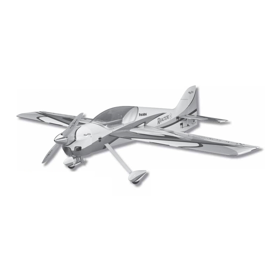
Performance series almost ready-to-fly 1.60 glow/43 cc gas sport aerobat
Hide thumbs
Also See for Performance Reactor:
- Instruction manual (36 pages) ,
- Instruction manual (24 pages)
Table of Contents
Advertisement
Quick Links
Wingspan: 84.5 in [2140mm]
2
2
Wing Area: 1556 in
[100.4dm
Weight: 14 – 17 lb [6350 – 7710g]
Wing Loading: 21 – 25 oz/ft
2
[63 – 77g/dm
Length: 85 in [2160mm]
®
Great Planes
Model Manufacturing Co. guarantees this kit to be
free from defects in both material and workmanship at the date
of purchase. This warranty does not cover any component parts
damaged by use or modifi cation. In no case shall Great Planes'
liability exceed the original cost of the purchased kit. Further,
Great Planes reserves the right to change or modify this warranty
without notice.
In that Great Planes has no control over the fi nal assembly or
material used for fi nal assembly, no liability shall be assumed nor
accepted for any damage resulting from the use by the user of
the fi nal user-assembled product. By the act of using the user-
assembled product, the user accepts all resulting liability.
If the buyer is not prepared to accept the liability associated
with the use of this product, the buyer is advised to return
this kit immediately in new and unused condition to the place
of purchase.
READ THROUGH THIS MANUAL BEFORE STARTING CONSTRUCTION. IT CONTAINS IMPORTANT
INSTRUCTIONS AND WARNINGS CONCERNING THE ASSEMBLY AND USE OF THIS MODEL.
Entire Contents © Copyright 2008
INSTRUCTION MANUAL
]
2
]
Radio:
5-channel minimum computer radio with mixing
functions, eight servos
Motor/Engine:
1.60 – 2.10 cu in [26 – 34cc] two-stroke,
2.00 – 2.20 cu in [33 – 36cc] four-stroke,
2.5 – 3.0 cu in [43 –50cc] gas
RimFire
WARRANTY
To make a warranty claim send the defective part or item to Hobby
Services at the address below:
3002 N. Apollo Dr., Suite 1
Champaign, IL 61822 USA
Include a letter stating your name, return shipping address, as
much contact information as possible (daytime telephone number,
fax number, e-mail address), a detailed description of the problem
and a photocopy of the purchase receipt. Upon receipt of the
package the problem will be evaluated as quickly as possible.
airsupport@greatplanes.com
™
80-75-230 out-runner brushless motor
Hobby Services
Champaign, Illinois
(217) 398-8970, Ext 5
GPMA1420MNL V1.0
Advertisement
Table of Contents

Related Manuals for GREAT PLANES Performance Reactor


Summary of Contents for GREAT PLANES Performance Reactor
-
Page 1: Instruction Manual
Include a letter stating your name, return shipping address, as In that Great Planes has no control over the fi nal assembly or much contact information as possible (daytime telephone number, material used for fi nal assembly, no liability shall be assumed nor... -
Page 2: Table Of Contents
INTRODUCTION ..............2 For the latest technical updates or manual corrections to the AMA ..................2 1.60 – 50cc Reactor 3D visit the Great Planes web site at SAFETY PRECAUTIONS ............2 DECISIONS YOU MUST MAKE ..........3 www.greatplanes.com. Open the “Airplanes” link, then Gas Engine Option &... -
Page 3: Decisions You Must Make
This is a partial list of items required to fi nish the 1.60 – 50cc series for 12S) –OR– Reactor 3D that may require planning or decision making before ❏ (3) Great Planes 5000mAh 4S LiPo (GPMP0636) (wired starting to build. Order numbers are provided in parentheses. -
Page 4: Additional Items Required
❏ Robart Super Stand II (ROBP1402) ❏ ™ C.G. Machine (GPMR2400) In order to fi nish your Reactor, you will need: ❏ 36" [914mm] Metal ruler (HCAR0475) ❏ Hobbico Builder’s Protractor (HCAR0490) ❏ (7) Great Planes large scale 1.5" single-side servo arm ❏... -
Page 5: Important Building Notes
Mail parts orders and payments by personal check to: 30-minute epoxy is specifi ed it is highly recommended that you use only 30-minute (or 45-minute) epoxy, because you Hobby Services will need the working time and/or the additional strength. 3002 N. Apollo Drive, Suite 1 Champaign, IL 61822 •... -
Page 6: Kit Inspection
If any parts are missing or are not of acceptable quality, or if you need assistance with assembly, contact Product Support. When reporting defective or missing parts, use the part names exactly as they are written in the Kit Contents list. Great Planes Product Support: 3002 N Apollo Drive, Suite 1 Champaign, IL 61822 Telephone: (217) 398-8970, ext. -
Page 7: Prepare For Assembly
The tip should be 1/2" [13mm] from the rib. Test fi t six-point type PREPARE FOR ASSEMBLY hinges into the wing so that the hinge pin is aligned with the hinge line. Defl ecting each hinge 90° will help you determine when the hinge pin is parallel with the hinge line. -
Page 8: Install The Aileron Servos
Install the Aileron Servos To get the best performance from your Reactor, we recommend that you use four Futaba 9155 digital servos. These precision servos have the right amount of torque (153 oz-in [11 kg-cm]) and will give you the best control. As a budget alternative you can use a metal geared servo with a minimum 100 oz-in [7.2... -
Page 9: Assemble The Pushrods
Assemble the Pushrods In this section you will build the aileron pushrods as well as the elevator and rudder pushrods. We’ll start with the four identical aileron pushrods and fi nish with the others which you can set aside to be used later. For this section you’ll need to have some silver solder and liquid silver-solder fl... -
Page 10: Install The Control Horns
Install the Control Horns ❏ ❏ 4. Use a hobby torch to heat both the clevis and the pushrod. Apply silver solder to the joint. The heat of the clevis and the pushrod should melt the solder, not the direct fl ame of the torch. -
Page 11: Build The Fuselage
BUILD THE FUSELAGE Main Landing Gear Installation ❏ 1. Locate the 3/16" x 2" [4.8 x 51mm] axles, four 3/16" [4.8mm] wheel collars, four set screws, two axle nuts, and the two main wheels. File fl at spots in the axle in the locations shown above. -
Page 12: Install The Horizontal Stabilizer
❏ ❏ 5. Attach the axles to the main landing gear legs using the 8. Attach the wheel pants to the landing gear legs using self-locking axle nut. four 4-40 x 1/2" [13mm] SHCS, four split ring lock washers, and four #4 washers. Use threadlocking compound on the screw threads. - Page 13 ❏ ❏ 3. Holding the stab in position, use a fi ne-point, felt-tip 6. Temporarily install the wings onto the fuselage using marker to trace lines onto the stab. Don’t forget to trace lines the wing tube and the plastic 1/4-20 x 1" [25mm] wing bolts. on the bottom side of the stab, too.
-
Page 14: Hinge The Horizontal Stabilizer
Hinge the Horizontal Stabilizer This section details the process for hinging the elevators. We performed the operation using 30-minute epoxy. This is generally enough time to do both elevators with one batch if you are completely prepared. If you are worried about accomplishing both sides, or you are working in a warm climate, do one elevator at a time. -
Page 15: Install The Elevator & Rudder Servos
❏ ❏ 3. Use 30-minute epoxy to glue your hinges in place. 2. Trim the covering from the elevator and rudder servo Remember to align them and to defl ect the rudder both ways bays on the left side of the fuselage. when you install it. -
Page 16: Install The Control Horns
❏ ❏ 5. Install the elevator and rudder servos. Use a 1/16" [1.6mm] 3. Center a control horn over the line that you made drill bit to drill the holes and use thin CA to harden the wood. making sure that the clevis holes are also centered over the hinge line. -
Page 17: Tail Gear Installation
❏ ❏ 7. Install the 5-1/4" [133mm] pushrod to the left elevator 4. Fit the tail gear assembly into the bushing and fi t the servo and elevator. tail gear retainer to the fuselage bottom as shown. Drill two 1/16" [1.6mm] holes into the fuselage using the retainer as a ❏... -
Page 18: Engine/Motor Installation
DA-50 gasoline engine, the O.S. 1.60 FX two-stroke glow nuts. Install one on the throttle arm and one on the choke engine, and the Great Planes ElectriFly 80mm brushless arm using threadlocking compound. Secure the ball links out-runner motor. Please jump to the section that applies to using the 2-56 hex nuts. - Page 19 ❏ 8. Locate the 2-56 x 36" [914mm] threaded one end rod. Measure 6" [152mm] from the unthreaded end and make a mark. Cut the wire at the mark and retain this portion. This ❏ 5. Cut a 1" [25mm] piece of outer pushrod tubing from will be referred to as “pushrod B.”...
- Page 20 threadlocking compound to the screw threads and install the 4-40 nut using a #4 washer and lock washer. ❏ 16. Locate the switch plate that fi ts your brand of radio switch. Four plates are supplied: two Futaba switch & Ernst charge jacks and two Hobbico heavy-duty &...
- Page 21 ❏ ❏ 20. Trim the covering from over the switch plate holes and 23. Wrap your ignition module in 1/4" [6.4mm] thick R/C install the ignition switch and charge jack. latex foam rubber. Mount the ignition module to one of the uprights or to the forward compartment fl...
- Page 22 ❏ 29. Build up the fuel tank stopper as shown and fi t the fuel tubes. Solder the fuel line barbs in place. ❏ 26. Turn the model over. Wrap a tie wrap around the spark plug lead to make a “P” clamp. Route the spark plug lead in a fashion that keeps it away from the muffl...
-
Page 23: Glow Engine Installation
This section contains installation steps for the O.S. 1.60 and grind off any remaining portion. FX two-stroke engine. The Great Planes engine mount supplied with this model is rated for 1.20 to 1.80-sized engines. If you are using an engine outside of this range, please use a suitable engine mount rated for it. - Page 24 beams. Position the engine on the mount so that the drive washer is 7-1/4" [184mm] from the fi rewall. Clamp the engine in this position. Drill and tap your engine mount using an 8-32 tap set. Install the engine to the mount using four 8-32 x 1"...
- Page 25 onto the pushrod tube from inside the fuselage. Note: The line pointing to the top of the tank. You may want to use a base of each standoff can be trimmed down for a custom fi t. felt-tip pen to mark which direction the vent line is pointed so that you know where the top of the tank is.
-
Page 26: Electric Brushless Motor Installation
Tape it in place and use a 9/32" [7.1mm] drill bit to drill four motor mount holes on the fi rewall for the Great Planes 80mm Standoff Mount. A center punch or scratch awl can be used to make a centering mark before you drill. Note: The Great Planes 80mm RimFire Standoff Mount set (GPMG1275) is available separately. - Page 27 ❏ 6. Use 80-grit sandpaper to roughen up the coated surface of the fi rewall and the equipment tray where the ESC tray will mount. Use epoxy to bond the ESC tray to the fuselage as shown. A piece of triangle stock is supplied to help secure the tray to the fi...
-
Page 28: Radio Installation
RADIO INSTALLATION Radio System Installation – Gas Engine ❏ 1. Prepare an ignition switch plate as you did earlier. ❏ 5. Locate the aft equipment tray, the tray doubler and the two side rails. Glue the tray doubler to the bottom of the tray. ❏... - Page 29 ❏ 10. Install a servo arm. Set your throttle servo to the full- throttle position and connect the pushrod. ❏ 7. Install the throttle servo in the aft tray. Drill four 1/16" [1.6mm] holes and harden them with thin CA. Note the position of the servo output shaft.
- Page 30 ❏ ❏ 13. Position and glue the pushrod standoffs and the outer 16. Wrap your receiver and battery pack with 1/4" [6.4mm] pushrod tube in place. thick latex foam. Use the straps you made to mount your battery and receiver to the aft equipment tray. ❏...
-
Page 31: Radio System Installation - Glow Engine
Radio System Installation – Glow Engine ❏ 5. Trim the covering from over the switch plate holes and install the switch and charge jack. ❏ 1. Locate the switch plate that fi ts your brand of radio switch. Four plates are supplied: two Futaba switch & Ernst charge jacks and two Hobbico heavy-duty &... -
Page 32: Radio System Installation - Electric Brushless
❏ 2. Use two 7 x 22mm and two 6 x 29mm sticks to make a fl ange for the charge plate. ❏ 9. Wrap your receiver and battery pack with 1/4" [6.4mm] thick latex foam. Use the straps you made to mount your battery and receiver to the center equipment tray. - Page 33 ❏ 8. Locate the non-adhesive backed hook and loop material. Make two sets of straps for your receiver and battery by joining a piece of “hook” material to a piece of “loop” material. ❏ 6. Locate the aft equipment tray and the two side rails. Align the tabs on each rail with the corresponding slots in the ❏...
-
Page 34: Final Assembly
FINAL ASSEMBLY Cowl & Prop Installation The following cowl installation instructions cover the DA-50 gasoline engine. Trimming the cowl to fi t other engines may require modifi cation of these procedures, but the basic idea is the same. For the DA-50 or similar gas engines, a template is provided in the back of this manual so that the engine does not have to be removed. - Page 35 ❏ 3. Remove the muffl er while leaving the template in place. ❏ 6. Fit the cowl centering tool to the cowl as shown. Use only two small drops of medium CA to tack the inside and the outside pieces together so that you can remove them easily later.
-
Page 36: Wing Installation
Wing Installation ❏ 9. Temporarily fi t the canopy and hatch. Fit the cowl once again, making sure to slide it back until the centering tool contacts the drive washer. Use a 1/16" [1.6mm] drill bit to make four 1/2" [13mm] deep holes in the fuselage sides (two ❏... -
Page 37: Canopy Installation
GET THE MODEL READY TO FLY Canopy Installation Check the Control Directions ❏ 1. Turn on the transmitter and receiver and center the trims. If necessary, remove the servo arms from the servos and reposition them so they are centered. Reinstall the screws that hold on the servo arms using threadlocking compound. -
Page 38: Set The Control Throws
HIGH RATE ELEVATOR: 1-1/2" [38mm], 15° up To ensure a successful fi rst fl ight, fl y your Reactor set 1-1/2" [38mm], 15° down up only according to the C.G. and control surface throws specifi ed in this manual. The throws and C.G. are not RUDDER: 4-3/4"... -
Page 39: Balance Your Model Laterally
43 and place it on or inside your model. model installed (ready to fl y) and an empty fuel tank, place the model on a Great Planes C.G. Machine, or lift it at the Charge Your Radio Batteries balance point you marked. -
Page 40: Engine & Motor Safety Precautions
Make sure that all electrical connections are soldered ENGINE & MOTOR SAFETY PRECAUTIONS properly. Run the motor for a few minutes and then check the wires and connections for excessive heat. Hot connections may indicate poor solder joints. Failure to follow these safety precautions may result in severe injury to yourself and others. -
Page 41: Battery Precautions/Connecting Batteries
Batteries of different voltages, but not different capacities Battery Precautions/Connecting Batteries may also be connected in Series: These are three 11.1V, 3200mAh batteries and one 7.4V, 3200mAh battery. When joined in Series, This is how to connect four batteries in Series: the result will be a 40.7V, 3200mAh battery. -
Page 42: Check List
❏ proximity of full-scale aircraft. Where necessary, an observer 3. Be certain the battery and receiver are securely shall be utilized to supervise fl ying to avoid having models fl y mounted in the fuselage. Simply stuffi ng them into in the proximity of full-scale aircraft. -
Page 43: Flying
air. At this moment it is likely that you will need to apply more FLYING right rudder to counteract engine torque. Be smooth on the elevator stick, allowing the model to establish a gentle climb to a safe altitude before turning into the traffi c pattern. Fuel Mixture Adjustments Flight A fully cowled engine may run at a higher temperature than... -
Page 44: 3D Flying
loop, check your altitude, mind the wind direction (anticipating begins to point downwards, reduce the throttle (to keep the rudder corrections that will be required to maintain heading), model from being pulled downwards). As the model fl attens remember to throttle back at the top, and make certain you out, add power to pull the model around. - Page 45 ROLLING HARRIER Great Planes 38% Extra 330S ARF The biggest ARF Great Planes has ever made is much easier to assemble and fl y than you’d guess – and it’s loaded with more extras than you’d ever expect. Despite a wingspan of 110 inches, this giant can be ready to fl...
- Page 46 COWL TRIMMING TEMPLATE COWL TRIMMING TEMPLATE Electric Installation Cutout Gasoline Engine Cowl Template...
- Page 47 ENGINE MOUNTING TEMPLATES ENGINE MOUNTING TEMPLATES...
- Page 48 ENGINE MOUNTING TEMPLATES ENGINE MOUNTING TEMPLATES...
Need help?
Do you have a question about the Performance Reactor and is the answer not in the manual?
Questions and answers