Table of Contents
Advertisement
Quick Links
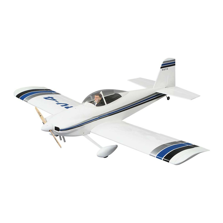
Wingspan: 54-5/8 in. (1388mm)
Wing Area: 628.8 sq. in. (40.56dm
Weight: 5-3/4 lbs to 6-1/4 lbs ( 2610g - 2850g)
Length: 49-5/8 in. (1260mm)
Wing Loading: 21 oz per sq ft to 22.9 oz per sq ft (64.4 grams per dm
Great Planes
Model Manufacturing Co. guarantees this kit to be free from defects in both material and workmanship
®
at the date of purchase. This warranty does not cover any component parts damaged by use or modification. In no case
shall Great Planes' liability exceed the original cost of the purchased kit. Further, Great Planes reserves the right
to change or modify this warranty without notice.
In that Great Planes has no control over the final assembly or material used for final assembly, no liability shall be
assumed nor accepted for any damage resulting from the use by the user of the final user-assembled product. By the act
of using the user-assembled product, the user accepts all resulting liability.
If the buyer is not prepared to accept the liability associated with the use of this product, the buyer is advised to
return this kit immediately in new and unused condition to the place of purchase.
READ THROUGH THIS MANUAL BEFORE STARTING
CONSTRUCTION.
INSTRUCTIONS AND WARNINGS CONCERNING THE
ASSEMBLY AND USE OF THIS MODEL.
RV44P03 for GPMA0180 V1.0
INSTRUCTION MANUAL
2
)
IT
CONTAINS
2
- 70.3 grams per dm
WARRANTY
IMPORTANT
P.O. Box 788
Printed In USA
2
)
Urbana, IL 61801
productsupport@greatplanes.com
Entire Contents © Copyright 2001
(217) 398-8970
Advertisement
Table of Contents

Related Manuals for GREAT PLANES RV-4


Summary of Contents for GREAT PLANES RV-4
-
Page 1: Instruction Manual
In that Great Planes has no control over the final assembly or material used for final assembly, no liability shall be assumed nor accepted for any damage resulting from the use by the user of the final user-assembled product. By the act of using the user-assembled product, the user accepts all resulting liability. -
Page 2: Table Of Contents
Mount the Landing Gear ....33 1. Your RV-4 should not be considered as a toy, but rather a Mount the Engine......34 sophisticated, working model that functions very much like a Install the Fuselage Components . -
Page 3: Decisions You Must Make
This is a list of items required to finish the RV-4 that must be build it; therefore, we cannot in any way guarantee the purchased separately. -
Page 4: Optional Supplies And Tools
Sealing Iron (TOPR2100) replaceable Easy-Touch Adhesive-backed Sandpaper. Heat Gun (TOPR2000) While building the RV-4, we used two 5-1/2" Bar Sanders Great Planes tap and drill set (GPMR8108) and two 11" Bar Sanders equipped with 80-grit and 2 - Rolls MonoKote ®... -
Page 5: Common Abbreviations
When you see the term test fit in the instructions, it Common Abbreviations means that you should first position the part on the assembly without using any glue, then slightly modify or custom fit the part as necessary for the best fit. Fuse = Fuselage LE = Leading Edge (front) Whenever the term glue is written you should rely upon... -
Page 6: Die-Cut Patterns
DIE-CUT PATTERNS... -
Page 7: Build The Tail Surfaces
2. Position the wing plan so the stab plan is over your flat building board. Cover the plan with Great Planes Plan Protector or wax paper so glue will not adhere. 6. Locate the 1/4" x 1/4" x 30" [6 x 6 x 750mm] balsa sticks. - Page 8 Do not shape the L.E. of the two elevator halves. time consuming and tedious. A really great time saver and accurate tool to make this job very simple is the Great Planes Slot Machine. This tool is available in a corded 110V AC.
-
Page 9: Build The Fin And Rudder
15. Bevel the L.E. of the elevator halves as shown on the 4. Locate the two die-cut 1/8" balsa rudder bases (RB). plan cross section. Glue them together forming the 1/4" balsa rudder base. 16. Trial fit the stab, hinges and elevator halves together. 5. -
Page 10: Build The Wing
From the bottom of the rudder up to the hole you have drilled, cut a groove 1/8" [3mm] wide. Hint: A perfect tool for this is the Great Planes Groove Tube (GPMR8140). 15. Locate the tailwheel wire assembly. Trial fit it into the hole and slot. - Page 11 Position the rib over the third set of notches and then twist it into the notch. Do not glue them to each other at this time. 6. Using your plan as your guide, install the remaining W3 ribs into the proper notches. Do not glue them in place at this time.
- Page 12 13. Locate a 3/32" x 4" x 30" [2.4 x 102 x 762mm] balsa 18. Locate the 3/32" x 5/16" x 24" [2.4 x 7.9 x 610mm] sheet. Cut a notch on the end of the sheet 7/8" [22.2mm] balsa cap strips. Cut the cap strips to fit between the from the L.E.
- Page 13 22. Sheet the top of the wing between the outboard W2 ribs from leftover 3/32" x 4" x 30" [2.4 x 102 x 762mm] balsa sheet. 27. From the end of the block where you sanded the 23. Locate the 5/8" x 1-3/4" x 7" [15.9 x 44 x 178mm] taper into the block, measure forward 3/4"...
- Page 14 30. Glue WBS to the balsa block between the end of the block and the line you have made on the balsa block. Position WBS so that it extends equally over each end of the balsa block. 33. When the balsa block is glued in place you will see that the block extends well beyond the W2 rib.
- Page 15 35. Turn the wing over on the bench so that you are 38. Sheet the area between WTE and WBS, gluing looking at the bottom of the wing. From the end of each of 3/32" [2.4mm] balsa sheet to the balsa block. the ribs measure back 1/2"...
- Page 16 44. Locate rib W5 and insert it into the plastic wing tip. Position the rib to be flush with the end of the wing tip then glue it in place with thin CA. At the trailing edge of the plastic 41.
-
Page 17: Build The Aileron And Flaps
Build the Ailerons & Flaps 1. Locate a 3/32" x 4" x 24" [2.4 x 102 x 610mm] balsa sheet. Cut it into two pieces 2" wide and cut each piece to a length of 21-3/16" [537.8mm]. These will become the top and bottom aileron/flap sheeting. - Page 18 12. Glue the remaining 3/32" x 2" x 21-3/16" [2.4 x 10² [537.8mm] balsa aileron / flap sheeting to the top of the aileron/flap. 8. Draw a line the length of the aileron/flap 1/4" [6mm] from the trailing edge of the sheeting. 13.
-
Page 19: Aileron Installation
3. Shape the leading edge of the aileron to match the shape shown on the aileron cross section on the plan. 17. Cut off the top and bottom of the wing trailing edge that extends above and below the surface of the wing. Sand the wing trailing edge to match the wing surface. -
Page 20: Flap Installation
Flap Installation You now have to decide if you want to build the wing with or without the flap option. If you decide to build it with the flap 1/16" you will need two additional standard 40 oz. servos and a 5th channel available on your radio system. - Page 21 6. At the location shown on the plans, cut two 1/2" [13mm] holes in the top of the wing for the aileron and flap servo leads to exit the wing. 2. Trial fit the dihedral brace into the wing by inserting it into the left wing panel and then twisting it into position between the wing spars.
-
Page 22: Build The Fuselage
13. This completes the construction of the wing. Take the time to get your bench cleaned up so you can get started on the fuselage! BUILD THE FUSELAGE 9. Working from the bottom of the wing, trial fit the aileron servo trays in place at the location on the plan. - Page 23 7. Position the fuselage side view on the building board. Cover the plan with Great Planes Plan Protector or wax paper so glue will not adhere to it. 11.Locate the 3/32" [2.4mm] die-cut balsa stab doubler 8.
- Page 24 17. Pin the fuselage top over the plans. Important! The fuselage will be assembled on the plans upside down. When you are assembling components that reference the right or left side of the fuselage, take the time to be sure you are working with the correct side of the fuselage.
- Page 25 22. Glue the right fuselage doubler (RFD) to the inside of 27. Glue the die-cut 1/8" [3mm] plywood bottom firewall the right fuselage side between F1 and F3. (BF) to the fuselage sides at the front of the fuselage. After BF is in place, glue F2-B to the fuselage sides and the top of BF.
- Page 26 31. Drill a 5/32" [4mm] through each of the punch marks on the firewall. 34. Cut off the fuselage side that extends beyond the firewall and sand the sides flush with the firewall. 32. Remove the fuselage from the plan and turn it over. Test fit the firewall to the fuselage.
- Page 27 37. From former F5B measure forward 1/2" [13mm] and make a mark on each side of the fuselage. With 6-minute epoxy glue the wing mounting plate to the fuselage sides, over the wing saddle doubler at the the mark you made. 39.
- Page 28 42. Locate the die-cut 1/8" [3mm] balsa formers F7A, F6A, F5A, F4A F3A and F2A. Glue them in place at the location and angles as shown on the plan. 46. Place FTC back into the notches in FRC, FLC and the firewall.
- Page 29 F3A and F4A and the deck stringers. Sand the sheeting to match the fuselage sides and sand the balsa deck stringers to match the deck sheeting. 49. Locate the 1/8" x 1/8" x 24" [3 x 3 x 610mm] balsa stick. Glue it in place on top of the basswood turtledeck stringer, making sure that it is glued in the center of the turtledeck stringer.
-
Page 30: Mount The Wing To The Fuselage
4. At the intersection of the lines on the wing bolt support, Mount the Wing to the Fuselage drill a 9/64" [3.6mm] (or use a #25 drill bit) pilot hole perpendicular to the bottom of the wing, through the wing 1.Turn the fuselage upside down. -
Page 31: Finish The Fuselage
3. Glue the CDB doublers to F5A. Position them the same 9. From left over 3/32" [2.4mm] balsa sheet cut a piece to way as you did for CDF. fit between the two wing fairings and a piece to fill the front of the fairing at the leading edge of the wing. - Page 32 9.From leftover 3/32" [2.4mm] balsa sheet, cut a piece to 12. Glue an additional 1/4" x 3/4" [6 x 19mm] balsa stick fit on top of BK and IP as shown. to the base centered on the line you have drawn. The stick needs to be perpendicular to the base.
-
Page 33: Mount The Landing Gear
Mount the Landing Gear 15. Using a razor plane and sanding block, shape the balsa blocks to match the fuselage. 1. Mark a line down the center of the landing gear plate. 16. Remove the fixture you've made to be sure that it slides out of the fuselage freely and that no glue is holding it in place. -
Page 34: Mount The Engine
5. Drill a 5/32" [4mm] hole through each of the locations you marked on the landing gear plate. 1. Cut the “spreader bars” from the supplied Great Planes motor mount, then use a hobby knife to remove any flashing leftover from the molding process so the halves fit together well. - Page 35 6. Mark the location for the holes for mounting the engine to the engine mount. Hint: The Great Planes Dead Center ™ Tool (GPMR8130) works fast and easy for marking these holes! 4.
-
Page 36: Install The Fuselage Components
8. Remove the engine from the firewall. Mix 1/4 ounce of 6-minute epoxy. Using an epoxy brush, apply a coating of epoxy to the entire firewall and the area under the firewall 3. Cut the tubes at an angle where they exit the fuselage. where the engine muffler will exit the cowl. - Page 37 the elevator. Using a felt tip pen, mark the drilling locations for the screws. Drill a 1/16" [1.6mm] hole through the marks. Attach a control horn to one of the elevator halves by inserting two 2-56 x 5/8" [15.9mm] machine screws through the control horn and elevator, attaching it to the nylon control horn plate.
-
Page 38: Install The Fuel Tank
13. On the threaded end of both elevator pushrods attach 21. Remove the stab and fin from the fuse. Put the fixture a clevis retainer and then a clevis by turning it onto the in place at the rear of the fuse. threaded end approximately 25 turns. -
Page 39: Finish The Radio Installation
Finish the Radio Installation 2. Now is the time to decide if you are going to fill the tank through a fuel filling valve or whether you are going to use a third line as a fill line. If you choose to use a fill valve, insert two 12"... -
Page 40: Finish The Servo Installation
Finish the Servo Installation 1. Install a servo into the aileron servo bay in the right wing following the radio manufacturer’s instructions. Center the servo, then install a servo arm onto the servo. The servo arm should be installed 90 degrees to the servo case and the arm should be pointing toward the wingtip. -
Page 41: Assemble The Cowl
Skip steps 7-11 If you did not install functional flaps. Assemble the Cowl 7. Install a servo into the flap servo bay in the right wing following the radio manufacturer’s instructions. Temporarily plug the flap servo into the receiver and then turn on the radio and transmitter. -
Page 42: Assemble The Wheel Pants
Install the Cowl 4. Cut the openings in the front of the cowl. Wet sand the entire cowl with 400-grit wet or dry sandpaper. The cowl is now ready to be primed. Assemble the Wheel Pants 1. Cut out the left and right half of the wheel pants along the cut line molded in the pants. -
Page 43: Install The Wheel Pants
Install the Wheel Pants 4. Position the cowling so that there is approximately 3/32" [2.4mm] between the back of the spinner plate and the front of the cowl. 1. Place a wheel pant onto a leg of the landing gear. Be sure you match the slot on one side of the wheel pant to the leg of the landing gear. -
Page 44: Prepare The Model For Covering
1. NEVER CUT THE COVERING DIRECTLY ON THE balsa wood has dried. SHEETING. The RV-4 depends on the sheeting for some of its strength. Modelers who cut through the covering tend to cut the sheeting and this will weaken the structure. -
Page 45: Install The Stab And Fin
Wet sand the the plastic parts between coats with Once you have the stab, fin and fuselage covered you can 400-grit sandpaper. Use Great Planes 1/8" [3mm] EZ-Mask permanently install the stab and fin to the fuselage. Flexible Masking Tape (GPMR1000) for masking sharp lines. -
Page 46: Canopy Installation
Do not use CA accelerator on any of the hinges and do not glue the hinges with anything but thin CA. Do not attempt to glue one half of the hinge at a time. The hinges will not be properly secured and could come out while the model is in flight. -
Page 47: Set The Control Throws
(ready to fly) and an empty fuel tank, place tested to arrive at the throws at which it flies best. Flying the model upside down on a Great Planes CG Machine, or your model at these throws will provide you with the lift it at the balance point you marked. -
Page 48: Preflight
Great Planes Balance Propellers (GPMQ4485) “stick-on” lead. A good place to add stick-on nose weight is to the firewall (don't attach weight to the cowl - it is not intended to support weight). Begin by placing incrementally increasing amounts of weight on the bottom of the fuse over the firewall until the model balances. -
Page 49: Engine Safety Precautions
2. I will not fly my model aircraft higher than approximately ENGINE SAFETY PRECAUTIONS 400 feet within 3 miles of an airport without notifying the airport operator. I will give right of way to and avoid flying in the proximity of full scale aircraft. Where necessary an Failure to follow these safety precautions may result in observer shall be used to supervise flying to avoid having severe injury to yourself and others. -
Page 50: Flying
Take it easy with the RV-4 for the first few flights, gradually 22. Range check your radio when you get to the flying field. getting acquainted with it as you gain confidence. Adjust the... -
Page 51: Landing
trims to maintain straight and level flight. After flying around Continue to lose altitude as you turn onto the downwind leg. for a while and while still at a safe altitude with plenty of fuel, Line up with the runway, allowing the nose to come down but practice slow flight and execute practice landing approaches maintaining airspeed and control. - Page 52 2-View Use the 2-view or photocopy it and use the copy to design your trim scheme.
Need help?
Do you have a question about the RV-4 and is the answer not in the manual?
Questions and answers