Table of Contents
Advertisement
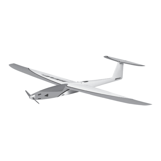
SPECIFICATIONS
Wingspan: 39.5 in [1000mm]
Length: 30.5 in [775mm]
Weight: 25– 28 oz [710 – 795 g]
Wing Area: 174 in
Wing Loading: 20.7– 23.2 oz/ft
WARRANTY
Great Planes
®
Model Manufacturing Co. guarantees this kit to
be free from defects in both material and workmanship at the
date of purchase. This warranty does not cover any component
parts damaged by use or modification. In no case shall Great
Planes' liability exceed the original cost of the purchased kit.
Further, Great Planes reserves the right to change or modify this
warranty without notice.
In that Great Planes has no control over the final assembly or
material used for final assembly, no liability shall be assumed nor
accepted for any damage resulting from the use by the user of
the final user-assembled product. By the act of using the
user-assembled product, the user accepts all resulting liability.
If the buyer is not prepared to accept the liability associated
with the use of this product, the buyer is advised to return
READ THROUGH THIS MANUAL BEFORE STARTING CONSTRUCTION. IT CONTAINS IMPORTANT
INSTRUCTIONS AND WARNINGS CONCERNING THE ASSEMBLY AND USE OF THIS MODEL.
®
Entire Contents © 2013 Hobbico,
Inc. All rights reserved.
2
2
[11.2 dm
]
2
2
[63– 71 g /dm
]
INSTRUCTION
Motor:
28-45-3600 Ammo
ESC:
50A for brushless motors
Radio: 5-channel, 3 servos,
programmable mixing
this kit immediately in new and unused condition to the
place of purchase.
To make a warranty claim send the defective part or item to
Hobby Services at the address below:
Hobby Services
3002 N. Apollo Dr. Suite 1
Champaign IL 61822 USA
Include a letter stating your name, return shipping address, as
much contact information as possible (daytime telephone
number, fax number, e-mail address), a detailed description of
the problem and a photocopy of the purchase receipt. Upon
receipt of the package the problem will be evaluated as quickly
as possible.
Champaign, Illinois
(217) 398-8970, Ext 5
airsupport@greatplanes.com
MANUAL
GPMA1806 Mnl
™
Advertisement
Table of Contents

Related Manuals for GREAT PLANES RIFLE1m


Summary of Contents for GREAT PLANES RIFLE1m
- Page 1 3002 N. Apollo Dr. Suite 1 Champaign IL 61822 USA In that Great Planes has no control over the final assembly or material used for final assembly, no liability shall be assumed nor Include a letter stating your name, return shipping address, as...
-
Page 2: Table Of Contents
For the latest technical updates or manual corrections to the the instructions may differ slightly from the photos. In those Rifl e 1M visit the Great Planes web site at www.greatplanes. instances the written instructions should be considered as com. Open the “Airplanes” link, then select the Rifl e 1M correct. -
Page 3: Additional Items Required
APC 4.5 x4.1 APC 5.25x 6.25 PROPELLER ❍ Electrical solder, soldering iron (APCQ4840) (APCQ4096) ❍ Great Planes 3/16" heat shrink tubing (GPMM1056) 28–45– 3600 Ammo Brushless MOTOR ❍ Du-Bro 1/8" [3mm] double-sided foam mounting tape Inrunner (GPMG5220) (DUBQ3551) Castle Creations Ice Lite 50 ❍... -
Page 4: Lipo Charger
Wing Set GPMA3401 Fuselage Set ORDERING REPLACEMENT PARTS GPMA3402 Horizontal Stabilizer Set Replacement parts for the Great Planes Rifl e 1M are available GPMA3403 Aileron Hatch Covers using the order numbers in the Replacement Parts List GPMA3404 Spinner that follows. The fastest, most economical service can be... -
Page 5: Assembly Instructions
ASSEMBLY INSTRUCTIONS Test-Mount the Motor Motor wires Bullet Battery connectors NOTE: If contemplating switching to a different motor in the future, don’t be too concerned about the possibility of new motor mounting screw holes that may overlap or interfere with the old holes. - Page 6 PROPELLER MOUNTING The collet shaft included with your Rifl e spinner is designed to work with the small O.D. propeller spacer ring that comes with all APC speed 400 propellers. Enlarge as necessary ❏ A. To prep the prop, press the spacer all the way into the propeller hub.
-
Page 7: Prepare The Motor And Esc
❏ 9. Use a metal fi le or sandpaper to deburr the end of the 13mm-14mm shaft. Remount the motor and test-fi t the spinner to see if the gap is right. Make adjustments if necessary. Prepare the Motor and ESC 6-1/2"... -
Page 8: Hook Up The Elevator
holes in a wood block for anchoring spare male bullets to hold the female bullets while you solder. (You may also solder the motor wires directly to the ESC if this is your preference, but don’t forget to slide on the heat shrink tubing fi... - Page 9 ❏ 5. Temporarily connect your elevator servo and ESC to the receiver with a battery and turn on the transmitter so you can power the servo. Again, make certain there are no mixes setup in your transmitter and that all the trims and sub trims are zeroed.
- Page 10 ❏ 11. With the elevator servo laying fl at on the bottom of ❏ the fuselage, make a sharp, 90° bend to the left 1/4" [6mm] 8. Connect the elevator pushrod to the elevator servo and from the end. slide the pushrod into the guide tube placing the servo in the fuselage.
- Page 11 ❏ 13. Remove the stabilizer and disconnect the pushrod, make that additional bend back, remount the stab and then test the elevator movement again. Adjust the angle of the bend as necessary until the elevator moves smoothly around center. Note: If, for some reason, you ever need to make a new elevator pushrod, one can be made from K&S .047"...
-
Page 12: Make The Aileron Pushrods
❏ 18. Connect the elevator servo, ESC and two 3" – 6" [75mm – 300mm] servo extensions for the aileron servos to the receiver. Tip: If your ESC has data logging (as does the recommended Ice Lite 50), connect the ESC to the receiver via. -
Page 13: Hook Up The Ailerons
Hook Up the Ailerons ❏ 1. Connect the aileron servos to the extensions coming out of the fuselage from the receiver. Connect a battery and turn on the transmitter so you can operate the servos. Program a mix so the servos respond opposite each other in the correct direction to aileron control stick inputs. - Page 14 the horn and servo align and that the arm and pushrod are centered in the opening. If necessary, adjust the bends in the ends of the pushrod to achieve this alignment. ❏ 9. Use 30-minute epoxy to securely glue the aileron horn into the aileron.
-
Page 15: Prepare The Model To Fly
PREPARE THE MODEL TO FLY Do not overlook the following two important procedures. The C.G. and control throws have been determined by thorough testing and record keeping. Later, you may wish to change the C.G. and throws to suit your taste, but the C.G. -
Page 16: Set The Control Throws
❏ 8. Bevel the front of the included plastic “battery spatula” and slide it under the battery for easier removal. ❏ 6. Place the Rifl e on the C.G. stand supported by the Set the Control Throws dowels on the tape strips on the bottom of the wing. If ❏... -
Page 17: Final Preparations
These are the recommended control surface throws: HIGH RATE LOW RATE Down Down 5/16" 1/4" 3/16" 3/16" ELEVATOR [8mm] [6.5mm] [5mm] [5mm] 18° 14° 11° 11° Down Down 5/16" 5/16" 3/16" 3/16" AILERONS [8mm] [8mm] [5mm] [5mm] 16° 9° 16° 9°... -
Page 18: Prefl Ight Ground Check
Prefl ight Ground Check Set a Flight Timer First on your agenda before fl ying should be setting a fl ight timer based on a conservative estimate of the length of time you can fl y. This is both so the motor does not quit unexpectedly (causing an unplanned landing) and/or so you do not over discharge your battery. -
Page 19: Spare Propellers
Spare Propellers FLYING As specifi ed, the APC 5.25 x 6.25 speed 400 propeller is Motor Safety Precautions recommended for the 2S sport setup. However, there are a few different propeller options for the speed setup. The 4.5 x Failure to follow these safety precautions may result 4.1 is the fi... -
Page 20: Flying
The tendency may be for motor torque to cause the Rifl e to roll left, but with a good launch into the wind you may not notice any torque at all and the Rifl e will aggressively climb skyward. Hint: Sometimes, during the thrill of the launch it can be easy to forget good mechanics (such as keeping the wings level or throwing the plane hard enough). -
Page 21: Landing
Landing 3. Get into the 1. Cut throttle landing pattern 2. Glide Throttle down, switch to high rates, glide around for about half a circuit, then extend your spoilerons before entering the landing approach. The perfect landing approach is a large, descending 180° turn. The procedure is simple and quick;... -
Page 22: Lateral Balance
After you land, always use a LiPo battery checker (GPMM3205) to check the individual cell voltages of your battery. The “resting,” “open” voltage of each cell when the batteries “recover” a few minutes after your fl ight should be no less than 3.7V per cell (which also equates to 20% capacity remaining). -
Page 23: Final Thoughts
Final Thoughts 3. Graceful pull with large, descending arc back to horizontal 2. Half flight roll 1. Pull to vertical up line Another maneuver to have in your repertoire is the “humpty bump.” The humpty not only makes it easier to align your Rifl e over the runway and low (for thrilling speed passes when you want to show off to any spectators), it can also be a safer maneuver as the plane is never on a trajectory inward.
Need help?
Do you have a question about the RIFLE1m and is the answer not in the manual?
Questions and answers