Table of Contents
Advertisement
Quick Links
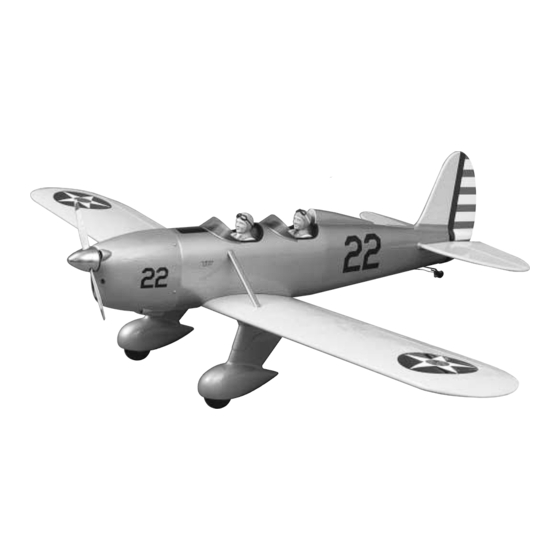
Wingspan: 82 in [2080mm]
Wing Area: 1066 sq in [69 dm
Weight: 10.25 - 11.5 lbs [4650 - 5220g]
Wing Loading: 22 - 25 oz/sq ft [67 - 76 g/dm
Length: 60 in [1525mm]
Radio: 4-5 channel with six servos
Engine: .61 - .91 cu in [10 - 15cc] two-stroke, .91 - 1.20 cu in [15 - 20cc] four-stroke
Great Planes
®
Model Manufacturing Co. guarantees this kit to be free from defects in both material and workmanship at the date of
purchase. This warranty does not cover any component parts damaged by use or modification. In no case shall Great Planes' liability
exceed the original cost of the purchased kit. Further, Great Planes reserves the right to change or modify this warranty without notice.
In that Great Planes has no control over the final assembly or material used for final assembly, no liability shall be assumed nor
accepted for any damage resulting from the use by the user of the final user-assembled product. By the act of using the user-assembled
product, the user accepts all resulting liability.
If the buyer is not prepared to accept the liability associated with the use of this product, the buyer is advised to return this
kit immediately in new and unused condition to the place of purchase.
READ THROUGH THIS MANUAL BEFORE
STARTING CONSTRUCTION. IT CONTAINS
IMPORTANT WARNINGS AND INSTRUCTIONS
CONCERNING THE ASSEMBLY AND USE OF
THIS MODEL.
© Copyright 2002
INSTRUCTION MANUAL
Almost Ready to Fly
2
]
2
]
A. R. F.
WARRANTY
1610 Interstate Drive Champaign, IL 61822
(217) 398-8970, Ext 2
airsupport@greatplanes.com
GPMZ0237 for GPMA1355 V1.0
Advertisement
Table of Contents

Related Manuals for GREAT PLANES Ryan STA-M


Summary of Contents for GREAT PLANES Ryan STA-M
-
Page 1: Instruction Manual
Further, Great Planes reserves the right to change or modify this warranty without notice. In that Great Planes has no control over the final assembly or material used for final assembly, no liability shall be assumed nor accepted for any damage resulting from the use by the user of the final user-assembled product. -
Page 2: Table Of Contents
Hook Up the Elevators .............18 corrections to the Ryan STA-M, visit the web site listed below Mount the Tailgear............20 and select the Great Planes Ryan STA-M ARF. If there is new Mount the Engine .............21 technical information or changes to this model, a “tech Mount the Cowl ..............22... -
Page 3: Scale Competition
Never blow into a part to If you would like photos of the full-size Ryan STA-M for scale remove fiberglass dust, as the dust will blow back into your documentation, or if you would like to study the photos to eyes. -
Page 4: Decisions You Must Make
In addition to the items listed in the “Decisions You Must Because the Ryan STA-M uses dual elevator servos and Make” section, following is the list of hardware and because the servos must move in opposite directions (due to accessories required to finish the Ryan. -
Page 5: Optional Supplies And Tools
4.8mm, 5.6mm, 6.7 (or 6.4mm), assembly without using any glue, then slightly modify or 6-32 tap (or Great Planes 6-32 tap and drill set with #36 custom fit the part as necessary for the best fit. drill - GPMR8102) -
Page 6: Kit Contents
If any parts are missing or are not of acceptable quality, or if you need assistance with assembly, contact Great Planes Product Support. When reporting defective or missing parts, use the part names exactly as they are written in the Kit Contents list on this page. -
Page 7: Ordering Replacement Parts
ORDERING REPLACEMENT PARTS To order replacement parts for the Great Planes Ryan STA-M ARF, use the order numbers in the Replacement Parts List that follows. Replacement parts are available only as listed. Not all parts are available separately (an aileron cannot be purchased separately, but is only available with the wing kit). -
Page 8: Tighten The Covering
TIGHTEN THE COVERING 1. If you have not done so already, remove the major parts of the kit from the box (wings, fuse, wheel pants, cowl, tail parts, etc.) and inspect them for damage. If any parts are damaged or missing, contact Product Support at the DRILL A 3/32"... -
Page 9: Hook Up The Ailerons
the trailing edge. The left aileron servo is mounted in a “mirror” Hook Up the Ailerons image (with the servo arm pointing toward the middle of the wing and the output shaft toward the trailing edge). Start with the right aileron. 1. -
Page 10: Mount The Landing Gear
Refer to this photo for the following two steps. 6. Round one end of both hardwood wing dowels. Use epoxy to glue the dowels in the wing with the rounded ends forward. Be certain approximately 1/2" [13mm] of the dowels protrudes from the wing. - Page 11 6. Cut the covering from the grooves in the landing gear rails in the bottom of the right wing panel. Trim the rail 2. Apply a fillet of epoxy mixed with milled fiberglass and the wing sheeting (where indicated by the arrow) to inside the pants where shown between the brackets in the accommodate the aft strut where it “angles up”...
-
Page 12: Assemble The Fuselage
ASSEMBLE THE FUSELAGE While working on the fuse, it helps to have a building stand. We use a Robart Super Stand II (ROBP1402). Mount the Stabilizer and Fin 1. The same as was done for the ailerons and the wing, prepare the elevator, stab, rudder and fin for hinging by cutting a strip of covering from the hinge slots and drilling holes. - Page 13 not enough, remove the stab from the fuselage. Lightly sand the slots in the fuselage as necessary to get the stab to align with the wing. Reinsert the stab and check the alignment. 6. Remove the wing from the fuse. Center the trailing edge of the stab in the fuse by taking accurate measurements from both tips to the sides of the fuse.
- Page 14 11. Peel the covering from the stab. Remove any ink with 15. Use 30-minute epoxy to glue the fin to the fuse. a piece of a tissue dampened with denatured alcohol. Before the epoxy hardens, use a Hobbico ® Builder's Triangle (HCAR0480) to see if the fin is perpendicular to the stab.
-
Page 15: Mount The Servos
Before the servo trays can be mounted, the blind nuts for the engine mount and the fuel tank must first be installed. 1. If using the included Great Planes adjustable .60 - 1.20 engine mount, cut out or photocopy the engine mount bolt pattern template provided on the back cover of this manual. - Page 16 4. Install the fuel tank so the neck fits through the hole in 8. Securely glue both 1/4" x 3/8" x 6-1/4" [6 x 10 x 160mm] the firewall. Be certain that you have installed the tank so the hardwood forward servo tray rails to the plywood inner fuse vent tube inside the tank is pointing upward.
-
Page 17: Hook Up The Rudder
Hook Up the Rudder 5. Insert the end of the cable back down through the swage, then loop it around and thread it back up through the swage (as indicated by the dashed line in the photo). 1. Cut the covering from the hole in both sides of the rudder for the 6-32 x 1-1/2"... - Page 18 9. Hold the fuselage vertically with the nose pointing upward. Guide the end of one of the cables with the clevis attached down through the fuse out one of the holes for the rudder. Connect the clevis to the torque rod horn on the rudder, then temporarily fit the rudder to the fin with a the hinges.
-
Page 19: Hook Up The Elevators
C. Apply a few drops of soldering flux to the end of the Hook Up the Elevators pushrod, then use a soldering iron or a torch to heat it. Coat the end of the pushrod with silver solder 1. Permanently join both elevators to the stab by gluing (GPMR8070) by touching the solder to it. -
Page 20: Mount The Tailgear
Mount the Tailgear Refer to this photo while mounting the tail gear. 4. Cut four 1" [25mm] pieces from the 36" [910mm] plastic tube (the one with the ridges). Use thick CA or epoxy to glue a tube in each of the four holes. Note: If using thick CA, work quickly. -
Page 21: Mount The Engine
7/8" [150mm] from the firewall. Temporarily hold the engine then bend it as necessary to connect to a screw lock connector on the throttle servo arm. Similar to the brace to the mount with a small “C”-clamp. Use a Great Planes Dead Center ™... -
Page 22: Mount The Cowl
Mount the Cowl 3. Determine your engine exhaust configuration. With the O.S. ® MAX .91 Surpass ™ II used on this model, an O.S. “in” type exhaust header pipe (OSMG2624) was used to position the muffler near the bottom of the cowl. (This 1. - Page 23 7. Use 30-minute epoxy to glue the cowl mount blocks into position. 11. Run the screws in and out of the cowl mount blocks several times to “cut” threads into the blocks. Add a few drops of thin CA to the holes to harden the “threads.” Be certain the CA has fully hardened, then mount the cowl to the fuse with four #4 x 5/8"...
-
Page 24: Finish The Radio Installation
1. Mount the on/off switch in a convenient location on the side of the fuselage opposite the engine exhaust. The switch on the model shown was mounted with a Great Planes Switch and Charge Jack (GPMM1000). This setup provides access to the battery charging cord from outside the model for quick field charging and battery monitoring. -
Page 25: Scale Details
angled slightly more than the bottom of the strut. Temporarily SCALE DETAILS hold the strut in position with a couple of T-pins. Mount the Wing Struts 90˚ Do the left wing strut first. Drill Holes Perpendicular 90˚ 9-3/8" Location of wing strut mounting block inside wing. - Page 26 2. Cut out the front and rear instrument panel stickers 6. Use a #11 blade to split both pieces of black rubber and place them in the model (the front instrument panel will tubing for the cockpit coaming. Fit the coaming around the have to be trimmed to accommodate the wing strut blocks).
-
Page 27: Apply The Decals
3. Position decal on the model where desired. Holding the decal down, use a paper towel to wipe most of the water away. 5. Use a Great Planes AccuThrow ™ (or a ruler) to 4. -
Page 28: Balance The Model Laterally
C.G. Machine to 4-3/16" IMPORTANT: The balance point and control surface throws [106mm]. If you do not have a Great Planes C.G. Machine, listed in this manual are the ones at which the Ryan flies use a felt-tip pen or 1/16"... -
Page 29: Identify Your Model
We use a Top Flite Precision Magnetic Prop Balancer ™ 1 oz. [29g] weight, or GPMQ4646 for the 2 oz. [57g] weight). (TOPQ5700) in the workshop and keep a Great Planes Great Planes (GPMQ4485) “stick-on” lead weight is also Fingertip Prop Balancer (GPMQ5000) in our flight box. -
Page 30: Final Preparations
gives off a great deal of deadly carbon monoxide. Therefore 12. Secure connections between servo wires and do not run the engine in a closed room or garage. Y-connectors or servo extensions and the connection between the battery pack and the on/off switch with vinyl tape, Get help from an experienced pilot when learning to heat shrink tubing or special clips suitable for that purpose. -
Page 31: Radio Control
When ready, place the model on the runway facing into the wind. Hold a bit of up elevator to keep the tail on the ground to The Ryan STA-M is a great flying sport airplane that flies maintain tail wheel steering, then gradually advance the smoothly and predictably, yet does not have the self-recovery throttle. -
Page 32: Landing
a new maneuver(s), improving a maneuver(s) you already Landing know, or learning how the model behaves in certain conditions (such as on high or low rates). This is not To initiate a landing approach, lower the throttle while on the necessarily to improve flight skills ( though it is never a bad downwind leg.
Need help?
Do you have a question about the Ryan STA-M and is the answer not in the manual?
Questions and answers