Table of Contents
Advertisement
Quick Links
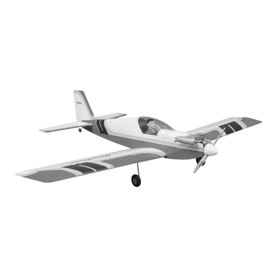
Wingspan: 60 in [1525mm]
Wing Area: 635 sq in [41 dm
Weight: 4.5–5.25 lb [2040–2350 g]
Wing Loading: 16-19 oz/sq ft [50–57 g/dm
Length: 46.5 in [1185mm]
Radio: 4-channel, 4 servos
Engine: .40-.50 cu in [6.5–8.0cc] two-stroke,
.40-.52 cu in [6.5–8.5cc] four-stroke
Great Planes
®
Model Manufacturing Co. box guarantees this kit to be free from defects in both material and workmanship at the date of purchase.
This warranty does not cover any component parts damaged by use or modification. In no case shall Great Planes' liability exceed the original cost
of the purchased kit. Further, Great Planes reserves the right to change or modify this warranty without notice.
In that Great Planes has no control over the final assembly or material used for final assembly, no liability shall be assumed nor accepted for any
damage resulting from the use by the user of the final user-assembled product. By the act of using the user-assembled product, the user accepts all
resulting liability.
If the buyer is not prepared to accept the liability associated with the use of this product, the buyer is advised to return this kit immediately
in new and unused condition to the place of purchase.
To make a warranty claim send the defective part or item to Hobby Services at the address below:
Include a letter stating your name, return shipping address, as much contact information as possible (daytime telephone number, fax number, e-mail
address), a detailed description of the problem and a photocopy of the purchase receipt. Upon receipt of the package the problem will be evaluated as
quickly as possible.
READ THROUGH THIS MANUAL BEFORE STARTING
CONSTRUCTION.
INSTRUCTIONS AND WARNINGS CONCERNING THE
ASSEMBLY AND USE OF THIS MODEL.
GPMZ0289 for GPMA0220 V1.0
INSTRUCTION MANUAL
2
]
2
]
3002 N. Apollo Dr. Suite 1
IT
CONTAINS
WARRANTY
Hobby Services
Champaign IL 61822
USA
IMPORTANT
™
Champaign, IL
(217) 398-8970, Ext. 5
airsupport@greatplanes.com
Entire Contents © Copyright 2003 Printed in USA
Advertisement
Table of Contents

Related Manuals for GREAT PLANES Rapture 40


Summary of Contents for GREAT PLANES Rapture 40
-
Page 1: Instruction Manual
Further, Great Planes reserves the right to change or modify this warranty without notice. In that Great Planes has no control over the final assembly or material used for final assembly, no liability shall be assumed nor accepted for any damage resulting from the use by the user of the final user-assembled product. -
Page 2: Table Of Contents
Build the Front Turtledeck............24 Build the Rear Turtledeck ............25 COVER THE MODEL ...............28 1. Your Rapture 40 should not be considered a toy, but Prepare the Model for Covering ..........28 rather a sophisticated, working model that functions very Cover the Model ................29 FINAL ASSEMBLY................30... -
Page 3: Additional Items Required
Planes at the address or telephone number below. If GPMQ4521, red–GPMQ4522,) requesting replacement parts, please provide the full kit 1" [25mm] Tail wheel (GPMQ4241) name (Rapture 40) and the part numbers as listed in the William’s Brothers #185 1/5-scale sportsman pilot Parts List. (WBRQ2485) -
Page 4: Covering & Covering Tools
Slot Machine ™ (110V, GPMR4010) over their location on the plan laid over the building board. CG Machine ™ (GPMR2400) Precision Magnetic Prop Balancer (TOPQ5700) The 16" x 36" x 3/4" [410 x 910 x 19mm] Great Planes Pro ™... -
Page 5: Types Of Wood
Building Board (GPMR6948) is suggested. A piece of 2' x 4' • Whenever the term glue is written you should rely upon [610 x 1220mm] Celotex ® ceiling tile is also suitable. Of your experience to decide what type of glue to use. When a course, the building board won’t be flat unless the specific type of adhesive works best for that step, the workbench beneath it is flat as well. -
Page 6: Die-Cut Patterns
DIE-CUT PATTERNS... -
Page 7: Build The Tail Surfaces
Cut the fin plan from the rest of the plan, or position the plan so the fin is over your building board. Cover the fin plan with Great Planes Plan Protector or wax paper so glue will not adhere to the paper. -
Page 8: Build The Stab & Elevators
Build the Stab & Elevators 1. Cut out the stab plan or position the plan so it is over your flat building board. Cover with Great Planes Plan Protector or wax paper. 2. The same way you cut the fin base for the fin, use the stab leading edge brace template on the plan to cut the stab leading edge brace from the 1/4"... - Page 9 3. Use a Great Planes Slot Machine to cut hinge slots on the centerlines at the marks. If you do not have a Slot Machine, use a #11 hobby blade to cut the hinge slots.
- Page 10 7. Set the fin and rudder aside. Mark the centerlines and hinge locations and cut the hinge slots on both elevators and the stab the same way, but don’t cut the “V” until instructed to do so. HOW TO SHARPEN A BRASS TUBE FOR CUTTING BALSA 8.
-
Page 11: Build The Wing
[6.4 x 6.4 x 760mm] balsa stick. Glue the 9" [230mm] stick on top of one end of the 28" [710mm] stick to make the wing jig. Start with the left panel so yours looks like the photos the first time through. 3. - Page 12 9. Using a small square to keep the ribs vertical, glue all the ribs except ribs R1 to the bottom spar. Also be certain the ribs are contacting the wing jig as you go. 7. Use medium CA or epoxy to glue the die-cut 1/8" [3.2mm] plywood R2A rib doublers to the correct side of three die-cut 3/32"...
- Page 13 Refer to this photo for the following three steps. 12. Fit, but do not glue rib R1 into position. Place a leftover piece of 3/32" [2.4mm] balsa on the plan against the bottom spar. 13. Fit, but do not glue the die-cut 3/32" [2.4mm] balsa shear web (DG) between R1 and R2.
- Page 14 23. Drill a #20 or 5/32" [4mm] hole through the landing gear rail and the landing gear block 11/16" [18mm] from the end. (The wire is 5/32" [4mm], but using a #20 drill, which is slightly larger than 5/32" [4mm], will make the gear a little easier to install and remove during construction.) 20.
- Page 15 31. Using the partially cut guide lines on R1, cut the 28. With the gear in the rail, use a ballpoint pen to rest of the way through and remove the section of balsa mark the leading edge of the wing at both ends of the gear. between the spars.
-
Page 16: Make The Ailerons
34. Cut a 1/2" [13mm] strip from the top sheeting over 3. Cut a matching groove in the wing trailing edge. the opening for the aileron servo. 35. Return to step 4 and build the right wing panel. Be 4. Roughen the plastic bearing tube on the torque rod sure to place the right panel wing plan over your building with coarse sandpaper. -
Page 17: Join The Wing
3. With the wings temporarily fit together, lay one wing panel flat on your workbench and measure the distance between the bottom of the other panel under the bottom spar at the tip. The distance should be 2-3/8" [60mm] plus or minus 3/8"... -
Page 18: Finish The Wing
2. Temporarily mount the landing gear with four nylon landing gear straps and eight #2 x 1/2" [13mm] screws. Drill 1/16" [1.6mm] holes for the screws. Use a fine-point ballpoint pen to draw the outline of the straps onto the sheeting. 5. -
Page 19: Build The Fuselage
5. Glue the die-cut plywood aileron servo tray to the top of the wing centered over the servo opening. 3. Glue the back of F1A to the front of F1B. From now on this assembly will be referred to as the firewall . Set the wing aside and get started on the fuselage. - Page 20 8. Glue the die-cut plywood formers F2 through F6 to the aft fuselage top. Do your best to get the formers vertical, but if they aren’t perfect the notches in the fuselage sides will square ‘em up anyway. 6. Use a ballpoint pen and a straightedge to draw a vertical line on the front of the firewall connecting the punchmarks in the middle.
-
Page 21: Mount The Wing
15. Use 30-minute epoxy and a few clamps to securely glue the firewall into position. Be certain the top of the firewall is fully contacting the fuselage top. Also note that the right side of the firewall should be all the way back in the notch in the fuselage side and the left side of the firewall should be all the way forward in the notch in the fuselage side. -
Page 22: Install The Guide Tubes, Fuel Tank & Engine
approximately 3/8" [10mm] of the dowels protrude from the leading edge. 7. Recheck the wing alignment. Using the holes in the bolt plate as a guide, drill #7 (.201" [5mm]) (or 13/64") holes through the wing and wing bolt plate in the fuselage. Be certain to hold the drill perpendicular to the bottom of the wing. - Page 23 2. Mix a small batch of 30-minute epoxy and microballoons. 6. Assemble the fuel tank (not included) according to the Use the mixture to glue the guide tubes in the exit slots in instructions that came with it. Mount the fuel tank to the tank the back of the fuselage.
-
Page 24: Build The Front Turtledeck
the hole in the firewall for the guide tube might have to be relocated to align with the carburetor arm on the engine. If necessary, determine where a new hole is to be drilled, then drill a 3/16" [4.8mm] hole. 15. -
Page 25: Build The Rear Turtledeck
2. Cut seven stringers for the front of the turtledeck from two 1/8" x 1/4" x 36" [3.2 x 6.4 x 910mm] balsa sticks. Glue the stringers into the notches in the stringers. Sand the ends of the stringers even with formers FD1 and FD3. 5. - Page 26 with the wing. If shifting the weight doesn’t do the trick, remove the stab and carefully sand the stab saddle to get the stab in alignment with the wing. 2. Glue together both die-cut 1/16" [1.6mm] balsa turtledeck formers TD3. Note that the formers are “flip- flopped”...
- Page 27 12. Remove the stab from the fuselage. Using a piece of leftover 1/4" x 1-1/2" [6.4 x 38mm] balsa as a fin spacer, place the fillet blocks on the fuselage with the spacer in between (where the fin would be). Center the rear of the spacer between the fuselage sides and center the front on the top, middle stringer.
-
Page 28: Cover The Model
template on the plan. Reinsert the spacer. Use a carving knife to carefully whittle down the fillet blocks around the spacer. When you start getting close to the final shape, switch to a razor plane followed by a bar sander. 18. -
Page 29: Cover The Model
Cover the Model 1. Cover the bottom, of one side, then the other side of the stabilizer first. Apply the covering up to the lines you marked noting the sides of the fuselage. Cut the front, tip 1. Gather the covering and tools you will use to cover the and back edges of the covering with a straightedge before model including plenty of new #11 blades, a metal sealing the edges down, but leave a small “handle”... -
Page 30: Final Assembly
3. Iron a piece of covering over the wing bolt plate before covering the rest of the wing. Cover one side, then the other side of the bottom of the wing, then cover one side, then the 2. Cover the top of the fuselage between the cockpit and the other side of the top of the wing. -
Page 31: Join The Control Surfaces
2. Bolt the wing to the fuselage. Apply 30-minute epoxy 3. Apply 30-minute epoxy in the groove and in the hole in to both sides of the stab and in the fuselage to the stab one of the ailerons for the torque rod. Also apply epoxy to saddle and the tail blocks. - Page 32 2. Thread a nylon clevis twenty full turns onto the threaded 5. Mount the elevator control horn to the elevator the end of a 36" [910mm] wire pushrod. Slip a silicone retainer same way. Note that the horn must be as close to the edge over the clevis, then connect the clevis to the outer hole in a of the elevator as possible so the screw does not interfere control horn.
- Page 33 nylon Faslink over the pushrod and snap it into place. Cut the pushrod approximately 1/16" [2mm] above the Faslink as shown in the photo. 9. Connect the pushrod to the outer hole in the rudder servo arm using the Faslink. Reconnect the clevis on the other end of the pushrod to the rudder control horn.
-
Page 34: Complete The Radio Installation
Refer to this photo for the following two steps. 17. Mount the aileron servo in the wing. The same as you should be doing all along, don’t forget to harden the screw 3. Mount the on/off receiver/battery switch to the side of holes with thin CA. -
Page 35: Finish The Cockpit
3. If the cockpit was covered with iron-on covering, cut away the covering so the pilot can be glued to bare wood. This is not necessary if the cockpit was painted. Glue the pilot into position with medium CA or epoxy. 4. -
Page 36: Apply The Decals
2. With the transmitter and receiver still on, check all the control surfaces to see if they are centered. If necessary, adjust IMPORTANT: The Rapture 40 has been extensively the clevises on the pushrods to center the control surfaces. flown and tested to arrive at the throws at which it flies best. -
Page 37: Balance The Model Laterally
Note: Do not rely upon the adhesive on the back of the lead weight to permanently hold it in place. Over time, fuel and 1. If using a Great Planes C.G. Machine set the rulers exhaust residue may soften the adhesive and cause the to 3-1/4"... -
Page 38: Balance The Propellers
™ Keep your face and body as well as all spectators away from the (TOPQ5700) in the workshop and keep a Great Planes plane of rotation of the propeller as you start and run the engine. Fingertip Prop Balancer (GPMQ5000) in our flight box. -
Page 39: Ama Safety Code (Excerpt)
To help avoid this, a check list is provided to make sure these important areas are not The Rapture 40 is a great-flying model that flies smoothly and overlooked. Many are covered in the instruction manual, predictably. -
Page 40: Takeoff
Take it easy with the Rapture for the first few flights, CAUTION (THIS APPLIES TO ALL R/C AIRPLANES): If, gradually getting acquainted with it as you gain confidence. while flying, you notice an alarming or unusual sound Adjust the trims to maintain straight and level flight. After such as a low-pitched “buzz,”... - Page 41 Available on 72 or 75MHz. FUTJ40** OTHER ITEMS AVAILABLE FROM GREAT PLANES Great Planes Ultra Sport ™ 40 Plus Kit If you’ve progressed past trainers and want an easy-to-fly sport model with a wide performance range, the 58.5" span Ultra Sport 40 Plus is for you! Its fully symmetrical O.S.
- Page 42 40 pounds. GPMR2400 control throws set differently from those recommended in the instructions. The Great Planes AccuThrow lets you quickly and easily measure actual throws first, so you can make necessary corrections before you fly. Large, no-slip rubber feet provide a firm grip on covered surfaces without denting or marring the finish.
- Page 43 BUILDING NOTES Kit Purchased Date: _______________________ Date Construction Finished: _________________ Where Purchased:_________________________ Finished Weight: __________________________ Date Construction Started: __________________ Date of First Flight: ________________________ FLIGHT LOG...
-
Page 44: Two View Drawing
TWO VIEW DRAWING Use copies of this page to plan your trim scheme...
Need help?
Do you have a question about the Rapture 40 and is the answer not in the manual?
Questions and answers