Table of Contents
Advertisement
A. R. F.
Almost Ready to Fly
Great Planes
®
Model Manufacturing Co. guarantees this kit to be free from defects in both material and workmanship at the date of
purchase. This warranty does not cover any component parts damaged by use or modification. In no case shall Great Planes' liability
exceed the original cost of the purchased kit. Further, Great Planes reserves the right to change or modify this warranty without notice.
In that Great Planes has no control over the final assembly or material used for final assembly, no liability shall be assumed nor
accepted for any damage resulting from the use by the user of the final user-assembled product. By the act of using the user-
assembled product, the user accepts all resulting liability.
If the buyer is not prepared to accept the liability associated with the use of this product, the buyer is advised to return this
kit immediately in new and unused condition to the place of purchase.
While this kit has been flight tested to exceed normal use, if the plane will be used for extremely high stress flying, such as racing, the
modeler is responsible for taking steps to reinforce the high stress points.
READ THROUGH THIS MANUAL BEFORE
STARTING CONSTRUCTION. IT CONTAINS
IMPORTANT WARNINGS AND INSTRUCTIONS
CONCERNING THE ASSEMBLY AND USE OF
THIS MODEL.
© Copyright 2000
INSTRUCTION MANUAL
WARRANTY
P.O. Box 788
Urbana, IL 61803
(217) 398-8970
GPMZ0226 for GPMA1345 V1.0
Advertisement
Table of Contents

Related Manuals for GREAT PLANES Ryan STA


Summary of Contents for GREAT PLANES Ryan STA
-
Page 1: Instruction Manual
Further, Great Planes reserves the right to change or modify this warranty without notice. In that Great Planes has no control over the final assembly or material used for final assembly, no liability shall be assumed nor accepted for any damage resulting from the use by the user of the final user-assembled product. -
Page 2: Table Of Contents
Optional Supplies and Tools ........4 General Inspection............4 When it's time to fly your Great Planes Ryan STA ARF, rest Important Building Notes ..........4 assured. Its flight performance more than lives up to its Parts List ..............5... -
Page 3: Precautions
If you are contacting us for replacement parts, please be sure to provide the full kit name (Great Planes Ryan ARF) and the part The Great Planes Ryan STA is an excellent sport-scale numbers as listed in the Parts List. -
Page 4: Additional Items Required
Inspect all items closely to forward servo tray (see step 8 on page 12). check for any damage. If any damage is found, contact the place where your Ryan STA was purchased, or Hobby Services, for a replacement of the damaged items. Building Notes Adhesive and Building Supplies •... -
Page 5: Parts List
• Whenever the term glue is written you should rely upon • When you get to each step, read that step completely your experience to decide what type of glue to use. When a through to the end before you begin. Frequently there is specific type of adhesive works best for that step the important information or a note at the end of the step that instructions will make a recommendation. -
Page 6: Build The Wing
BUILD THE WING Join the Wing Halves 4. Separate the wings and remove the joiners. Thoroughly coat all mating surfaces, including the inside of the wings where the joiners fit, with 30-minute epoxy, then glue the wings together. Use masking tape to tightly hold them together until the epoxy has hardened. -
Page 7: Hinge The Ailerons
Use care to cut just through the covering, while not cutting into the wood. Glue the wing bolt plate into position. After the glue hardens, use the holes in the top of the wing as a guide to drill 17/64" (or 1/4") holes through the wing bolt plate. 4. -
Page 8: Mount The Landing Gear
Mount the Landing Gear Do the right one first so yours looks like the photos. Refer to this photo for the following two steps. 4. Drill 1/16" holes in the wing for mounting the aileron servo. Add a few drops of thin CA to the holes and allow to harden, then mount the servo to the wing. -
Page 9: Join The Control Surfaces To The Fuse
4. Reposition the axle onto the gear and tighten the 8. Now that the final position of the wheel pant, wheel screw. Be certain that the screw has “landed” on the flat spot and wheel collars has been determined, remove the wheel and that the axle has remained parallel with the leading edge pant and the wheel from the landing gear. -
Page 10: Install The Fin
8. Peel the covering from the stab. Remove any ink with a piece of a tissue dampened with denatured alcohol. 4. Turn the fuse upside-down. Stick a T-pin through the 9. Thoroughly coat all joining areas of the stab and fuse with bottom of the fuse centered over the middle stringer. -
Page 11: Hook Up The Controls
Now that we've fit the rudder fairing, let's set it aside and 5. There should be four hinge slots for the rudder—three hook up the rudder. The rudder fairing will be permanently in the fin and one in the fuse. If there isn't one in the fuse, mounted after the controls are hooked up. - Page 12 (it may be easier to do this without the servos in the inside the tank does not contact the rear of the tank. tray). For additional strength, mix Great Planes Pro Milled Otherwise, the line may become stuck during flight and Fiberglass (GPMR6165) into the epoxy.
-
Page 13: Mount The Tailgear
D. Join the clevis to the pushrod. Add another drop of flux, then heat and add solder. The same as before, the heat of the parts being soldered should melt the solder thus allowing it to flow. Allow the joint to cool without disturbing. Avoid excess blobs, but make certain the joint is thoroughly soldered. -
Page 14: Join The Tail Fairings
wire by bending the threaded end to join the steering arm on Join the Tail Fairings the right side of the tail gear. Connect the pushrod to the tail gear with a nylon ball link, a 0-80 threaded ball and a 0-80 nut and a small drop of threadlocker. -
Page 15: Mount The Engine
1. Use four 8-32 x 1-1/4" SHCS, #8 lock washers and #8 of your engine and secure it with a nylon retainer. Drill a flat washers to mount the Great Planes 60-120 Adjustable 3/16" hole through the firewall in alignment with the Quick Engine Mount to the firewall, simultaneously adjusting the Connector. -
Page 16: Mount The Cowl
7. Fashion a mount for a fuel filler valve, should you decide to use one, from 1/8" plywood (not included). As shown in the photo, we used a Great Planes Easy-Fueler ™ for glow fuel (not included with this kit, GPMQ4160). We also used a Model Products #021 Remote Single Lock remote glow plug adapter (MODP1221). -
Page 17: Finish Radio Installation
As shown in the photo we use a Great Planes Switch & Charge Jack Mounting Set (GPMM1000). The external charge jack allows us to monitor the voltage of the receiver battery pack before each flight without removing the wing. -
Page 18: Final Scale Details
the top stringer aft of the cockpit and routed the antenna Finish the Cockpit through a piece of tubing exiting the fuse. The other end of the antenna was connected to a hook made from a cut-off servo arm connected to a small rubber band and a T-pin 1. -
Page 19: Get The Model Ready To Fly
TRANSMITTER 3. Make certain that the control surfaces and the 7. Apply Great Planes 1/4" white Kwik Stripe (GPMQ1610) carburetor respond in the correct direction as shown in the striping tape around the base of the windscreen where it meets diagram above. -
Page 20: Balance The Model
(ready to fly) and an empty fuel tank, place IMPORTANT: The balance point and control surface the model upside-down on a Great Planes CG Machine, or throws listed in this manual are the ones at which the Ryan lift it upside-down at the balance point you marked. -
Page 21: Preflight
We use a Top Flite Precision Magnetic Prop Balancer Do not use your fingers to flip the propeller. Make certain the (TOPQ5700) in the workshop and keep a Great Planes glow plug clip or connector is secure so that it will not pop Fingertip Prop Balancer (GPMQ5000) in our flight box. -
Page 22: Ama Safety Code (Excerpt)
Do not use hands, fingers or any other Since the Great Planes Ryan STA qualifies as a “giant body part to try to stop the engine. To stop a gasoline scale” model and is therefore eligible to fly in IMAA... - Page 23 5.2 Engines with battery power ignition systems must have displacement are 6.0 cu. in. for two-stroke and 9.6 cu. in. for a switch to turn off the power from the battery pack to four-stroke engines. These maximums apply only to AMA disable the engine from firing.
-
Page 24: Check List
Y-connectors or servo extensions and the connection between your battery pack and the on/off switch with vinyl tape, heat The Ryan STA is a great flying sport airplane that flies smoothly and predictably, yet does not have the self- shrink tubing or special clips suitable for that purpose. -
Page 25: Fuel Mixture Adjustment
handles at slower speeds. Practice slow flight and landing Fuel Mixture Adjustment approaches while still at a comfortable altitude. Add power to see how she climbs as well. Continue to fly around, A fully cowled engine may run at a higher temperature than executing various maneuvers and making mental notes (or an un-cowled engine. - Page 26 BUILDING NOTES Kit Purchased Date: _______________________ Date Construction Finished: _________________ Where Purchased:_________________________ Finished Weight: __________________________ Date Construction Started: __________________ Date of First Flight: ________________________ FLIGHT LOG...
-
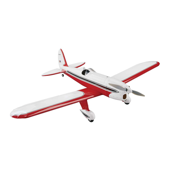
Page 27: Engine Mount Template
MonoKote covering. Smooth in flight, it blends the prepainted fiberglass cowl, replica cylinder heads, muscle of dual aileron servos with the aerobatic potential of adjustable engine mount and Great Planes-brand hardware. a symmetrical airfoil. Note: Pilot figure not included. Note: Pilot figure not included. - Page 28 Plus, the AT-6 offers the strength of fiberglass parts factory-painted to match the preapplied wood...the dependability of Great Planes hardware...and the MonoKote covering. Competition mounted servos (2 each for fine finish of Top Flite MonoKote film. Fixed landing gear is...
Need help?
Do you have a question about the Ryan STA and is the answer not in the manual?
Questions and answers