Table of Contents
Advertisement
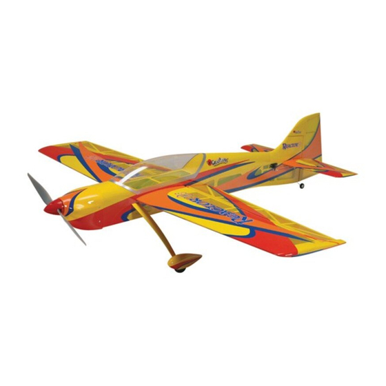
Wingspan: 58 in [1475mm]
Wing Area: 745 sq in [48.1 dm2]
Weight: 5.25–6.16 lb [2410–2720g]
Wing Loading: 16-18 oz/sq ft [50–57 g/dm2]
Length: 59 in [1500mm]
Radio: 4-channel minimum with (5) 50 oz/in high-torque standard/mini servos
Power System: RimFire
™
42-60-480kV Out-runner brushless motor with 60A brushless
ESC and two 11.1V, 3200mAh LiPo batteries (in series), or
.46-.51 cu in [7.5cc] two-stroke, or .70 cu in [11.5cc] four-stroke
Great Planes
®
Model Manufacturing Co. guarantees this kit to be free from defects in both material and workmanship at the date of purchase.
This warranty does not cover any component parts damaged by use or modification. In no case shall Great Planes' liability exceed the
original cost of the purchased kit. Further, Great Planes reserves the right to change or modify this warranty without notice.
In that Great Planes has no control over the final assembly or material used for final assembly, no liability shall be assumed nor accepted for
any damage resulting from the use by the user of the final user-assembled product. By the act of using the user-assembled product, the user
accepts all resulting liability.
If the buyer is not prepared to accept the liability associated with the use of this product, the buyer is advised to return this kit
immediately in new and unused condition to the place of purchase.
To make a warranty claim send the defective part or item to Hobby Services at the address below:
Include a letter stating your name, return shipping address, as much contact information as possible (daytime telephone number, fax number,
e-mail address), a detailed description of the problem and a photocopy of the purchase receipt. Upon receipt of the package the problem will
be evaluated as quickly as possible.
READ THROUGH THIS MANUAL BEFORE STARTING
CONSTRUCTION. IT CONTAINS IMPORTANT INSTRUCTIONS
AND WARNINGS CONCERNING THE ASSEMBLY AND
USE OF THIS MODEL.
Entire Contents © Copyright 2006
INSTRUCTION MANUAL
WARRANTY
Hobby Services
3002 N. Apollo Dr., Suite 1
Champaign, IL 61822
USA
Champaign, Illinois
(217) 398-8970, Ext 5
airsupport@greatplanes.com
GPMZ1021 for GPMA1021 V1.0
Advertisement
Table of Contents

Related Manuals for GREAT PLANES Reactor


Summary of Contents for GREAT PLANES Reactor
-
Page 1: Instruction Manual
Further, Great Planes reserves the right to change or modify this warranty without notice. In that Great Planes has no control over the final assembly or material used for final assembly, no liability shall be assumed nor accepted for any damage resulting from the use by the user of the final user-assembled product. -
Page 2: Table Of Contents
Building Stand .............5 For the latest technical updates or manual corrections to the IMPORTANT BUILDING NOTES ........5 Reactor .46 3D ARF visit the Great Planes web site at ORDERING REPLACEMENT PARTS ......5 www.greatplanes.com. Open the “Airplanes” link, then select KIT INSPECTION ..............6 the Reactor ARF. -
Page 3: Safety Precautions
PROTECT YOUR MODEL, YOURSELF DECISIONS YOU MUST MAKE & OTHERS...FOLLOW THESE This is a partial list of items required to finish the Reactor .46 IMPORTANT SAFETY PRECAUTIONS 3D ARF that may require planning or decision making before starting to build. Order numbers are provided in parentheses. -
Page 4: Additional Items Required
❏ This is the list of hardware and accessories required to finish Hobbico 8-Piece Ball Tip Hex L Wrench SAE (HCAR0520) ❏ the Reactor .46 3D ARF. Order numbers are provided in Great Planes Precision Prop Reamer Standard parentheses: (GPMQ5006) ❏... -
Page 5: Champaign, Il
ORDERING REPLACEMENT PARTS Replacement parts for the Great Planes Reactor .46 3D ARF are available using the order numbers in the Replacement Parts List that follows. The fastest, most economical service can be provided by your hobby dealer or mail-order company. -
Page 6: Kit Inspection
If any parts are missing or are not of acceptable quality, or if you need assistance with assembly, contact Product Support. When reporting defective or missing parts, use the part names exactly as they are written in the Kit Contents list. Great Planes Product Support 3002 N. Apollo Drive, Suite 1 Champaign, IL 61822 Telephone: (217) 398-8970, ext. -
Page 7: Preparations
PREPARATIONS ❏ 1. If you have not done so already, remove the major parts of the kit from the box and inspect for damage. If any parts are damaged or missing, contact Product Support at the address or telephone number listed in the “Kit Inspection”... -
Page 8: Install The Aileron Servos And Pushrods
Install the Aileron Servos and Pushrods ❏ ❏ 1. Installing the servos in the wing will require the use of one 12" [305 mm] servo extension for each aileron servo. One Y-harness connector is required and is used to allow the aileron servos to plug into one slot in your receiver. - Page 9 ❏ ❏ ❏ ❏ 4. Temporarily position the aileron servo into the servo 6. Place a large nylon control horn on the aileron, bay with the servo spline towards the leading edge of the positioning it as shown in the sketch and aligning it with the wing.
-
Page 10: Finish The Wing
Finish the Wing ❏ 1. Locate the four 1/4" [6mm] diameter anti-rotation dowels. 2-56(.074") Pushrod Wire Servo Arm 1/4” [6mm] ❏ ❏ Faslink 2. Coat half of two anti-rotation dowels with epoxy and ❏ ❏ 8. Use tape or a small clamp to hold the aileron in the insert them into the forward and aft holes in the wing panel neutral position. -
Page 11: Assemble The Fuselage
ASSEMBLE THE FUSELAGE Install the Rudder and Tail Gear ❏ 3. Test fit the plastic bracket of the tail gear assembly into the slot in the fuselage. Temporarily install CA hinges into the rudder. Guide the 90 degree bend in the tail gear wire into the hole you drilled in the rudder and fit the rudder into place with CA hinges as far as it will go (do not glue the ❏... -
Page 12: Assemble & Install The Main Gear
❏ 2. Slide the wheel pants over the axles into position and temporarily attach them to the landing gear using four ❏ 5. Install the tail wheel onto the tail wheel wire followed 4-40 x 3/8" [9.5mm] phillips screws. Position the wheel in the by the wheel collar and set screw. -
Page 13: Install The Elevators & Stabilizer
Install the Elevators and Horizontal Stab ❏ 1. Just as you did with the ailerons and rudder, prepare the hinge slots in the horizontal stabilizer and elevators by enlarging the slots as necessary, drilling a 3/32" [2.4mm] hole at the center of each slot and trimming away the covering from around each slot. - Page 14 C = C ❏ ❏ 5. Secure the wings to the fuse using four 4-40 x 1/2" 7. Measure the distance from the tip of each wing to the [13mm] SHCS and four #4 flat washers. tip of the stab. Adjust the stab until the distance from the tip of the stab to the tip of the wing is equal on both sides.
-
Page 15: Install The Tail Servos And Pushrods
Install the Tail Servos and Pushrods HOW TO CUT COVERING FROM BALSA Use a soldering iron to cut the covering from the stab. The tip of the soldering iron doesn’t have to be sharp, but a fine tip does work best. Allow the iron to heat fully. Use a straightedge to guide the soldering iron at a rate that will just melt the covering and not burn into the wood. -
Page 16: Engine Installation
plate. The plate is visible from the top of the elevators. Using a 1/16" [2.4mm] drill bit, make a 1/2" [13mm] deep hole at the marks you made, being sure not to drill completely through the elevators. Install and remove a #2 x 1/2" [13mm] sheet metal screw into each of the holes. -
Page 17: Brushless Motor Installation
Use the four-stroke instructions as a guide for a 2-stroke installation. The Reactor .46 ARF can be changed from a glow engine setup to a brushless motor or vice-versa with little difficulty, so your power plant choice during original assembly does not have to be permanent. -
Page 18: Four-Stroke Glow Engine Installation
❏ ❏ 5. Attach the prop adapter with the screws included with 8. Secure the ESC to the plane in the location shown and the motor. Be sure to use threadlocking compound. connect it to the motor. You may need to use a scrap piece of balsa to lower the ESC in order for it to fit part way through the cooling hole cutout. -
Page 19: Install The Fuel Tank & Throttle Servo
❏ 2. The fuel tank for the Reactor utilizes a three line system. There is a fill line, carb line, and vent line (to muffler). The fill line will allow fueling and defueling without unhooking any ❏... - Page 20 ❏ 4. Cut the fill line and carb line tubes such that the tubes extend 1/2" [13mm] out from both ends of the stopper. Install the metal plates on the front and back of the stopper and loosely thread the 3 x 26mm phillips machine screw through the plates.
- Page 21 ❏ 11. A throttle servo tray and two servo adapter plates are included in the kit. The small adapter plate will hold a 1.1" x 0.5" ❏ 9. Cut another piece 4" [102mm] long and two pieces 3/8" [28 x 13mm] micro servo such as the Futaba S3101. The large [9.5mm] long.
-
Page 22: Finish The Model
❏ 14. Position the outer pushrod tube so that the aft end is approximately 1/4" [6mm] behind the front edge of the throttle ❏ servo tray. Mark the tube at the firewall, remove it from the 17. Glue the cooling hole cover in place as shown. plane and cut it to length at the mark you made. -
Page 23: Install The Radio System (Brushless Motor)
Install the Radio System (Brushless Motor) ❏ 2. Install four magnets into the magnet holes in the fuselage in the same manner as you did with the hatch. Be sure to install the magnets with the polarity in the correct ❏... - Page 24 (not included) to the side of the fuselage. Be sure that the receptacle you are installing will not interfere with the flight packs. The Great Planes switch and charge jack receptacle is too large for this plane. We used an Ernst charge receptacle, part number ERNM3001.
-
Page 25: Install The Radio System (Glow Engine)
❏ 2. Feed the receiver antenna through the antenna tube installed in the fuselage. Temporarily remove the left elevator servo from the fuselage to expose the aft end of the antenna ❏ 7. Make a strap out of the remaining hook and loop tube. -
Page 26: Install The Cowl, Canopy And Spinner
Install the Cowl, Canopy and Spinner ❏ 3. Fit the cowl onto the fuselage and temporarily secure the spinner backplate onto the prop shaft. You may need to drill out the hole in the backplate or use a prop reamer to match the diameter of your prop shaft (6mm diameter for the C42- 60-480kV RimFire, 5/16"... -
Page 27: Apply The Decals
Apply the Decals 1. Use scissors or a sharp hobby knife to cut the decals from the sheet. 2. Be certain the model is clean and free from oily fingerprints and dust. Prepare a dishpan or small bucket with a mixture of liquid dish soap and warm water—about one teaspoon of soap per gallon of water. -
Page 28: Set The Control Throws
If, is “nose heavy” and the battery pack and/or receiver must be after you have become accustomed to the way the Reactor shifted aft or weight must be added to the tail to balance (a... -
Page 29: Balance The Model Laterally
We use a Top Flite Precision Magnetic Prop Balancer that side is heavy. Balance the airplane by adding weight to the (TOPQ5700) in the workshop and keep a Great Planes other wing tip. An airplane that has been laterally balanced Fingertip Prop Balancer (GPMQ5000) in our flight box. -
Page 30: Motor Safety Precautions
• Use a “chicken stick” or electric starter to start the engine. MOTOR SAFETY PRECAUTIONS Do not use your fingers to flip the propeller. Make certain the glow plug clip or connector is secure so that it will not pop off or otherwise get into the running propeller. Failure to follow these safety precautions may result in severe injury to yourself and others. -
Page 31: Ama Safety Code (Excerpts )
AMA SAFETY CODE ( CHECK LIST EXCERPTS ❏ Read and abide by the following excerpts from the Academy 1. Fuelproof all areas exposed to fuel or exhaust residue of Model Aeronautics Safety Code. For the complete Safety such as the cowl mounting blocks, wing saddle area, etc. Code refer to Model Aviation magazine, the AMA web site or ❏... -
Page 32: Flying
When you become accustom to the takeoff characteristics of an un-cowled engine. For this reason, the fuel mixture the Reactor, as little as 10 feet is needed to get airborne. should be richened so the engine runs at about 200 rpm Building some speed on the runway and applying full up below peak speed. -
Page 33: 3D Flying
One final note about flying your model. Have a goal or flight WATERFALLS plan in mind for every flight. This can be learning a new maneuver(s), improving a maneuver(s) you already know, or learning how the model behaves in certain conditions (such as on high or low rates). - Page 34 rudder to maintain Knife Edge, not climbing or diving. Perform may have to make constant aileron (wing walking) and rudder one full right negative Tumble by maintaining your rudder corrections for this maneuver. As the nose of the plane comes setting while applying full throttle, full down elevator, and full up, start adding in a little bit of power to help maintain right aileron, releasing in time to end again flying Knife Edge to...
- Page 35 ALSO AVAILABLE FROM GREAT PLANES O.S. ® .46 AX ABL O.S. ® FS-70 Surpass ™ Includes: #A3 glow plug, E-3010 muffler Displacement: 0.455 cu in (7.5cc) Requires: glow fuel, prop Bore: 0.866 in (22.0mm) Suggested prop sizes: 10.5x6, 11x6-8, 12x6-7 Stroke: 0.772 in (19.6mm)
- Page 36 ALSO AVAILABLE FROM GREAT PLANES Great Planes ® 25% YAK 54 3D Glow/Gas ARF Wingspan: 81 in (2055 mm) Wing Area: 1138 sq in (73.4 dm²) Weight RTF: 12.5-15.25 lb (5.67-6.86 kg) Wing Loading: 25-30 oz/sq ft (77-93 g/dm²) Length: 68 in (1727 mm) Engine Required: 2-stroke 1.6-1.8 cu in (25-30 cc) or 4-stroke 1.8-2.1 cu in (30-36 cc) glow or 1.9-2.6 cu in (32-43 cc) gasoline...
Need help?
Do you have a question about the Reactor and is the answer not in the manual?
Questions and answers