
Related Manuals for Wegener iPump 6400


Summary of Contents for Wegener iPump 6400
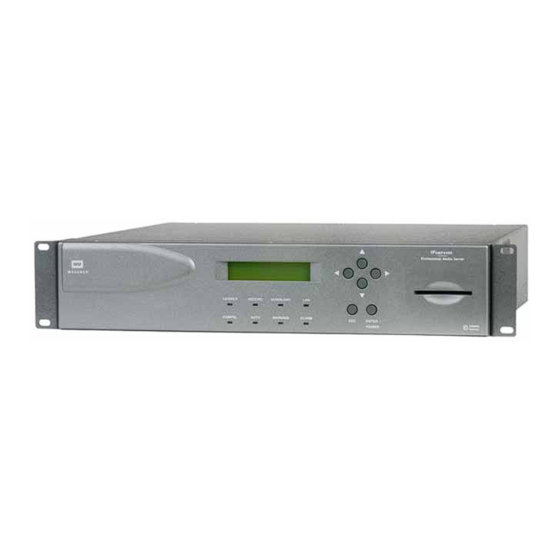
- Page 1 6400 Professional Media Server iPump 6400 Professional Media Server User’s Manual 800009-01 Rev. J...
- Page 2 Wegener Communications, Inc. Technology Park/Johns Creek 11350 Technology Circle Duluth, GA 30097-1502 Phone: 770-814-4000 Fax: 770-623-0698 The WEGENER iPump 6400 is approved under FCC Part 15B Class A , UL1950 , CSA , and 800009-01 Rev. J www.wegener.com...
-
Page 3: Table Of Contents
1.3 iPump 6400 Specifications ........ - Page 4 2.3 iPump 6400 Connections ........
- Page 5 615 Setup ..........43 3.9 iPump 6400 Operations by Function ......43 Monitor iPump 6400 Status .
- Page 6 6400 Help ........
-
Page 7: List Of Figures
Figure 3.4: Selectable field ..................21 Figure 3.5: iPump 6400 front panel LED indicators...........21 Figure 3.6: iPump 6400 web browser control setup process ........24 Figure 3.7: iPump 6400 web browser Status tab ............25 Figure 3.8: iPump 6400 LCD menu structure ............26 Figure 3.9:... - Page 8 6400 User’s Manual Large Playlist Navigation tools ..............57 Figure 3.28: iPump 6400 web browser Help tab ............60 Figure 3.29: Menu navigation to switch unit software ..........60 Figure 3.30: Menu navigation to Version Info ..............61 Figure 3.31: viii 800009-01 Rev. J...
- Page 9 Balanced analog and AES/EBU digital audio connector pin functions ..16 Table 2.5: RF port selection signals .................17 Table 2.6: iPump 6400 front panel LED indicator descriptions .........22 Table 3.1: iPump 6400 web browser control setup procedure ........24 Table 3.2: iPump 6400 pre-configured Transport In Settings ........27 Table 3.3:...
- Page 10 6400 User’s Manual 800009-01 Rev. J www.wegener.com...
-
Page 11: Chapter 1 General Information
IP digital transmission with media management and server storage. At a given time, up to 260 hours of media content can be stored on a single iPump 6400 (with optional, large disk capacity) and served out via Ethernet according to current need or predetermined schedules. -
Page 12: Physical Description
File playing may be initiated by a predetermined schedule via Compel or by a schedule stored internally to the iPump 6400 . The user may also command playing of files directly from a web browser or from the front panel. Two recorded programs (or one recorded and one live) may be played simultaneously on iPump 6400 s with an optional second decoder. -
Page 13: Routing
25 Mbps. The iPump 6400 's file download and record functions may be used to load the unit with content for playout (according to a pre-arranged schedule if desired) at any time. This can www.wegener.com... -
Page 14: Files Served To Lan
Compel network. HTML Control Control of the iPump 6400 is available from any web browser on the LAN to which it is connected or via the internet if desired. The IP address and subnet mask can be displayed and changed at the iPump 6400 front panel. - Page 15 6400 User’s Manual Model Number Option Name Designator Description Position Second Decoder Type 0 - No second decoder (middle slot) 1 - Basic decoder 2 - professional 4:2:0 decoder with analog outputs 3 - professional 4:2:2 decoder with analog outputs...
-
Page 16: 1.3 Ipump 6400 Specifications
General Information 1.3 iPump 6400 Specifications Technical Table 1.2: iPump 6400 technical specifications i Specifications Characteristic Specification Input Frequency tuning via front panel control or Compel Input FrequencyRange 950 to 2150 MHz Input Impedance 75 ohms LNB Power 250 mA max, 22 kHz tone control vertical polarity: 12.4 to 14.0 VDC... -
Page 17: 1.4 Safety Summary
31° C decreasing linearly to 50% relative humidity at 40° C. 1.4 Safety Summary The iPump 6400 is designed for safe use with few special precautions required of the user. The following items are basic precautions to use when installing and working with your iPump 6400 Do not open the iPump 6400 's chassis cover. -
Page 18: 1.5 Glossary Of Terms And Abbreviations
Table 1.3: Glossary of terms and abbreviations Term Definition Alternating current Alarm A condition or notification of a condition that prevents the from performing properly. iPump 6400 Assured File Delivery. Authorized Describes an which has the ability through iPump 6400 Compel Conditional Access decrypt programs encrypted by the software. - Page 19 6400 User’s Manual Term Definition Program Number A numerical code representing a program. QPSK Quadrature phase shift keying. QPSK is a digital frequency modulation technique used for sending data over coaxial cable networks. Radio frequency Server message block - a protocol for requesting services from and reading and writing to a file server.
- Page 20 General Information This page intentionally left blank 800009-01 Rev. J www.wegener.com...
-
Page 21: Chapter 2 Installation
Equipment should be installed such that airflow required for safe operation of the equipment is not compromised. To ensure adequate air flow, the iPump 6400 should be arranged in a rack with at least one empty rack unit between it and adjacent equipment and with adequate clearance around both side vents. -
Page 22: Circuit Overloading
Procedure connecting cables. Screw or bolt the supports securely to the equipment rack. 2. Place the iPump 6400 on its supports and use four anchor screws or bolts and nuts to secure the unit's front brackets to the rack. A 1 RU gap (1.75 in) must be left between the iPump 6400 and any adjacent equipment WA RNING above or below it to provide adequate air flow around the unit. -
Page 23: 2.3 Ipump 6400 Connections
ASI input option.) iPump 6400 2. Connect a suitable audio monitor or monitors to the iPump 6400 's audio port(s) [ b1 ] (on both decoders if your iPump 6400 includes a second decoder). Also connect audio monitoring to the auxiliary audio port [ b2 ] if your iPump 6400 includes that option. -
Page 24: Alarm Connector Details
Installation Table 2.1: iPump 6400 connector details Designation Connector Type Signal Description Additional Information female Type F 950 to 2150 MHz RF carrier A extension cable is shipped already RF IN from antenna LNB attached to the RF IN port to allow easier access for attaching your RF input. -
Page 25: Ethernet/Lan Port Details
RX_D2- Receive Data- Unused Unused Connector details are somewhat different for iPump 6400 s having the optional decoder with Optional digital audio and video output. Figure 2.3 below illustrates the rear-panel layout of this Decoder with optional decoder. Connector details are listed in Table 2.4 . -
Page 26: Pro Audio Decoder
Analog Ch A (Left +) AES Ch A + Ground The output connectors for the professional audio model of the iPump 6400 look somewhat Pro Audio different than the standard video decoder connectors. The iPump 6400 Pro Audio Decoder Decoder allows streams of different sample-rates and formats to be mixed together and sent to both analog and digital AES/EBU outputs. -
Page 27: Multiswitch Connection Details
When operating a multiswitch, use Table 2.6 to identify the line signals corresponding to Multiswitch each iPump 6400 RF port selection. On a typical multiswitch (as in Figure 2.6 below), these Connection ports will be in order from left to right as viewed from the side holding the input connectors. - Page 28 Installation This page intentionally left blank 800009-01 Rev. J www.wegener.com...
-
Page 29: Chapter 3 Operation
Compel signal if that signal is temporarily lost. 3.2 Front-panel Controls and Indicators There are three major parts of the iPump 6400 's front panel controls and indicators: the liquid-crystal display (LCD), the six push buttons, and the eight LED indicators. -
Page 30: Liquid-Crystal Display (Lcd)
The iPump 6400 's LCD indicates unit status and prompts for and reflects user input. The Liquid-Crystal LCD displays the iPump 6400 's unit label and serial number on the top line following startup. Display (LCD) The home screen also alternately displays the input signal’s frequency, data rate, and FEC ratio in the lower left corner and continuously displays the current signal-to-noise ratio in the lower right. -
Page 31: Editable Filename Field
3. To save a selection, press ENTER when the LCD displays the desired option. To cancel any changes, press ESC before pressing ENTER . These eight light-emitting diodes (LEDs) provide status information about the iPump 6400 and its processes. Table 3.1 on page 22 provides the meaning of the color and state of each Indicators LED. -
Page 32: Table 3.1: Ipump 6400 Front Panel Led Indicator Descriptions
Operation Table 3.1: iPump 6400 front panel LED indicator descriptions Indicator Color and State Meaning Label GREEN constant Receiver is tracking carrier. CARRIER GREEN slow blink Receiver is not tracking carrier. GREEN constant is recording a program. RECORD iPump 6400 is not recording. -
Page 33: 3.3 Startup/Shutdown Procedures
3. Press the ENTER button to select Unit Shutdown .When prompted, press the ENTER button again to confirm. 4. In less than 30 seconds, the iPump 6400 powers down and the LCD and LEDs go out. The is now ready for a normal startup. Initiate a normal startup by pressing the iPump 6400 button. -
Page 34: Web Browser Operations Startup
See Network Setup on page 42. Static vs. dynamic setup The iPump 6400 allows you to configure your IP setup as either static or dynamic. The static setup allows you to set a fixed IP address, whereas a dynamic setup or DHCP (Dynamic Host Configuration Protocol) selects a temporary IP address from your network. -
Page 35: Web Browser Access
6400 IP SETUP screen. You must include leading zeros in addresses entered from the iPump 6400 front panel, but Web Browser not when entering them from the browser interface. For example, IP address Access (as entered from the iPump 6400 front panel) must be entered as 128.092.050.004... -
Page 36: 3.4 Front Panel Operation
Operation 3.4 Front Panel Operation Operate the iPump 6400 from the front panel using the push buttons and the LCD. Menu screens on the LCD direct you to screens that control various operating parameters or display information about the iPump 6400 . Menu titles represent either a category of control... -
Page 37: Pre-Configured Transport In Settings
) are preconfigured and should only be changed if advised by your satellite Transport In Warning operator. Table 3.3 lists these settings as they are originally configured from the factory. Settings Table 3.3: iPump 6400 pre-configured Transport In Settings Parameter Application / Description Preset Value Default appropriate for Ku-band reception. 5150 MHz... -
Page 38: Lnb Type
Data ENTER TRANSPORT IN STATUS: TRACKING: Eb/No = XX. X Display is shown. If the unit is Transport In Status iPump 6400 , then the screen also displays Tracking Eb/No Menu CURRENT CHANNEL Editable ENTER DOWNLINK FREQUENCY: XXXXX. XX MHz... -
Page 39: Lnb Dc Power Setting
6400 User’s Manual For proper multiswitch operation, LNB DC Power must be set to Note: Figure 3.12: Menu navigation to set LNB type Table 3.6: Procedure for setting LNB LO Frequencys Begin from the Transport In Setup screen. See Navigation to Transport In Setup Screen on page 27. -
Page 40: Front Panel Additional Unit Setup
!" Return Path Setup !" Set up the date and time for the iPump 6400 during the initial setup. Use the front panel Navigation to navigation buttons to go to the Date/Time screen as shown in Figure 3.14 . Date/Time Setup Screen Figure 3.14: LCD Menu navigation to Date/Time Setup screen... -
Page 41: Navigation To Unit Label Setup Screen
Unit Label Setup Screen Figure 3.15: LCD menu navigation to Set Unit Label screen Set the Unit Label , the name assigned to the iPump 6400 , during the initial setup. Table 3.9 Unit Label details the label-entering procedure. Setup... -
Page 42: Navigation To Http Proxy Screens
ENTER HTTP Proxy Setup press to cancel the changes. The returns you iPump 6400 to the screen. HTTP Proxy Setup Navigation to The Return Path is the communications return channel used for delivering status and reporting If your local network uses a proxy server, you may information to the network control system. -
Page 43: Return Path Setup
Editable Bkup SERVER IP 000.000.00.000 Select numbers until the Backup Server IP address is complete. 3.7 Optional Front Panel Screens Your iPump 6400 may be configured for optional features including: Modem !" Genlock !" SMB access control !"... -
Page 44: Modem Setup
Editable PPP PASSWORD <ENTER> Press ENTER and select characters until the password is complete. Selectable DONE? <YES> <NO - ESC> _________________ Press ENTER to confirm the username or ESC to return to the PPP USERNAME screen. 800009-01 Rev. J www.wegener.com... -
Page 45: Navigation To Genlock Setup Screen
6400 User’s Manual Use the Genlock setup if you have a professional video decoder installed in your iPump Navigation to . You have the option to enable or disable synchronization of the video output signal to Genlock 6400 an external timing source commonly referred to as Genlock. -
Page 46: Smb Screen Setup
Stops SMB service After a period of inactivity, the iPump 6400 front panel display returns to the home screen. Screen Park The Screen Park feature allows you to "park" the LCD screen to any front panel display. An Setup example of this feature’s use is to park the LCD screen on the current time display so that... -
Page 47: Decoder Setup
6400 User’s Manual Figure 3.21: iPump 6400 web browser Setup tab If your iPump 6400 has the optional second decoder, then your system can simultaneously Decoder play two live programs from the same DVB carrier. Setup Decoder Operation The primary decoder, allows your system to play a single live program from the DVB carrier. -
Page 48: Genlock Setup
Cancel button. Selecting Activate or Cancel returns you to the previous screen. If you have a professional video decoder installed in your iPump 6400 , you have the option Genlock to enable or disable synchronization of the video output signal to an external timing source Setup commonly referred to as Genlock. -
Page 49: User State Vs. Current State
. A program number of zero (0) indicates the first available program Decoder (#) found in the input stream. For the iPump 6400 to play satellite multicast streams, the IP settings must contain the IP Setup correct PIDs (Packet IDs).The iPump 6400 extracts the MPE (Multi Protocol Encapsulated) IP data from the input transport stream. -
Page 50: Lnb Setup
Cancel button. Selecting Activate or Cancel returns you to the previous screen. For compatibility between your satellite dish and the iPump 6400 , select the LNB (Low LNB Setup Noise Band) converter to match the one installed on your satellite dish. -
Page 51: Snr Alarm Warnings Setup
Cancel button. Selecting Activate or Cancel returns you to the previous screen. Set the iPump 6400 to configure "trip points" at which Alarm or Warning indications are SNR Alarm triggered when the RF signal yields low or marginal Eb/No readings. -
Page 52: Modem Setup
6400 using the new network settings. Setup Entering the wrong network settings could leave you disconnected from the iPump 6400 . If disconnected, correct the network settings using the front panel. See Web Browser on page 24. -
Page 53: Return Path Setup
2. To send a one-time command to the iPump 615 , click the Submit button. 3.9 iPump 6400 Operations by Function Most iPump 6400 functions can be performed either locally from the front panel or from a web browser attached to the iPump 6400 via an Ethernet . Web browser operation is described in this section because after the initial configuration, most users use the web browser rather than the front panel. -
Page 54: Monitor Alarm And Warnings
6400 cleared. To return to the Status tab, click OK . When set up for live program play, the iPump 6400 decodes an incoming MPEG stream Live Program from the received DVB satellite signal and decrypts and decodes the audio and/or video Play from the selected program to the connected audio and video monitors. -
Page 55: Procedure For Live Program Play
39. Receive Setup Procedure for Live Program Play If your iPump 6400 has additional decoders, repeat the steps below using the Edit button for or Decoder 3 . Decoder 2 Each grouping of parameters are setup independently. Selecting Activate or Cancel Note: returns you to the previous screen.. -
Page 56: Record Program To File
7. To save your changes, click the Activate button.To discard any changes, click the Cancel button. 8. If your iPump 6400 has the optional decoders, repeat the steps above using the Edit button for Decoder 2 or Decoder 3 . -
Page 57: Figure 3.23: Ipump 6400 Web Browser Rec/Play Tab
Continuous Record checkbox. The iPump 6400 continues to record until commanded to stop, or until the available disk space is consumed. If the storage capacity is filled over 99% during recording, the iPump 6400 begins Note: deleting existing files in chronological order beginning with the oldest file. -
Page 58: Play Recorded Program File
The file size in bytes is shown in parentheses adjacent to each filename. !" The name of the current directory is shown just above the list of files. !" To view file names in the next higher directory, double click [-Previous Directory-] !" available. 800009-01 Rev. J www.wegener.com... -
Page 59: File Management
The Record/Play chart on the left displays the name and time remaining of the selected file or playlist. The Play to Decoder 2 option is for dual-decoder iPump 6400 s. The Play to Decoder Note: option is for iPump 6400 s with an external decoder for the SMD 515 connected to your LAN. -
Page 60: Figure 3.24: Ipump 6400 Web Browser Files Tab
Operation Figure 3.24: iPump 6400 web browser Files tab 2. To select a file, click the filename under the File Manager list. To navigate the list: The file size in bytes is shown in parentheses adjacent to each filename. !"... -
Page 61: File Streaming And Routing
Compel If needed, click Disable to temporarily suspend scheduled operations. Click Enable to return to scheduled operations. The iPump 6400 resumes performing operations according to the scheduled times. Operations scheduled for times during which the unit is "disabled" are not performed. -
Page 62: Playlist Management
Playlists are stored in nonvolatile memory so that they remain available after Management the unit restarts. In the context of the iPump 6400 playlists, an item is a single media file. A playlist consists of one or more items that are played from beginning to end in sequential order. -
Page 63: About Playlists
!" Timed playlists have a specific start time (for example, 1:00 am). As a permanent source for the iPump 6400, a timed playlist resumes playing after a power outage. See Setting a start on page 59. time for a playlist Immediate playlist’s items do not have set times and are considered a temporary source... -
Page 64: Looping Styles
6400 will not select the last played randomly selected item. When you add an item using the Sequential tag to your playlist , the iPump 6400 plays the items in order from first to last and then looping back around to the first item in the directory for each pass of the item in the playlist. -
Page 65: Saving A Playlist
6400 User’s Manual Saving a playlist To save or duplicate an open playlist: On the menu To... The Playlist Builder... bar, click, save the playlist saves the playlist. The browser displays: Save Saved playlist [name] successfully...returning to editor duplicate the 1.opens a text box for the playlist name. -
Page 66: Deleting Items From A Playlist
Example: If the current playlist page displays items 201-300 and you delete item 220, then the open playlist page adjusts to display items 171-270. Clicking the Next Page button, resets the window and displays items 301-400. See Figure 3.28 and on page 57. Table 3.28 800009-01 Rev. J www.wegener.com... -
Page 67: Procedures For Customizing Playlists
2. Enter the playlist’s description and then click Save . The Playlist Builder lists the new description in the playlist bar. Creating and deleting Aliases Using a playlist alias allows you to easily recognize the playlist and allows the iPump 6400 to perform the playlist functionality transparently. www.wegener.com... -
Page 68: Adding On-Screen Graphics
1. In the active playlist, select the appropriate Show OSG check box for an item to display the selected OSG. OSG drop- Intro/Outro Show OSG X & Y coordinates down list Time box check boxes 2. Select an image from the OSG drop-down list. 800009-01 Rev. J www.wegener.com... -
Page 69: Setting A Start Time For A Playlist
When a playlist with a start time is scheduled for playback, then the decoder is Note: turned off until the iPump 6400’ s local system clock equals the playlist’s start time. Caution: Start times should not be set for items that follow Random or Sequential tagged items since the actual play times for these cannot be determined. -
Page 70: Ipump 6400 Help
Click the View Online Manual hyperlink to open the PDF. Figure 3.29: iPump 6400 web browser Help tab 3.10 Unit Software Switch The Unit Software Switch function is only available from the iPump 6400 front panel. Software and Table 3.13 detail the procedure to switch between versions of application Switch Figure 3.30... -
Page 71: Verify Software Version Procedure
After switching the software, you may want to verify that the intended software is in use. Use Verify the procedure below to verify the version of software in use on the iPump 6400 . Software Version 1. - Page 72 Operation 800009-01 Rev. J www.wegener.com...
-
Page 73: Chapter 4 Maintenance And Troubleshooting
No Functions loss of ac power. Do the following: At All 1. Check that the power switch is set to the ON position. See Figure 2.2: iPump 6400 rear- on page 13. panel connector locations 2. Check that ac power cord is firmly connected at both ends. -
Page 74: Led Indicators
Maintenance and Troubleshooting The iPump 6400 displays only one alarm or warning condition at a time on the LCD. When multiple alarm or warning conditions exist, the iPump 6400 displays those conditions in the Indicators order of importance with the most critical condition displaying first. After clearing the more critical item(s), the iPump 6400 displays any additional alarms or warnings. -
Page 75: Fault (Alarm/Warning) Indications
6400 User’s Manual Faults in the unit operation trigger warning and alarm indications. The iPump 6400 presents Fault (Alarm/ the indications to the local user via: Warning) Indications front-panel LEDs !" LCD information screens !" the state of Alarm Relays !"... - Page 76 File to play/stream doesn't exist File Doesn't Exist File to play/stream is an unsupported format Invalid File Format Storage device is approaching maximum capacity Disk Usage > 90% File to play/stream can't be opened Cannot Open File 800009-01 Rev. J www.wegener.com...
-
Page 77: Chapter 5 Customer Service
5.2 Technical Support If the unit should fail to perform as described, if you need help resolving problems with your , or for questions about obtaining service for your iPump 6400 , please contact iPump 6400 at ( 770) 814-4057 , Fax (678) 624-0294 , or e- Wegener Communications Customer Service mail service@wegener.com . - Page 78 Customer Service This page intentionally left blank 800009-01 Rev. J www.wegener.com...
-
Page 79: Ndex
... . . 4 iPump 6400 operations ..19 dynamic setup ....24 definition . - Page 80 SNR Alarm/Warning Setup 28, 29 iPump 6400....2 overview ....1 model number Live Program Play.
- Page 81 ....53 iPump 6400 ....19 schedules ....51 Playlist builder .
- Page 82 Y value maximum ... 59 web ..... 43 800009-01 Rev. J www.wegener.com...
- Page 83 6400 User’s Manual www.wegener.com 800009-01 Rev. J...
- Page 85 " 2007 Wegener Communications, Inc. All rights reserved. 800009-01 Rev. J Tenth Edition: August 2007 Wegener Communications, Inc. Technology Park/Johns Creek 11350 Technology Circle Duluth, GA 30097-1502 Phone: 770-814-4000 Fax: 770-623-0698...
Need help?
Do you have a question about the iPump 6400 and is the answer not in the manual?
Questions and answers