Magnum Energy ME Series Operator's Manual
Me series inverter / chargers
Hide thumbs
Also See for ME Series:
- Owner's manual (62 pages) ,
- Operator's manual (44 pages) ,
- Removal and replacement (2 pages)
Table of Contents
Advertisement
Quick Links
Advertisement
Chapters
Table of Contents
Troubleshooting

Related Manuals for Magnum Energy ME Series


Summary of Contents for Magnum Energy ME Series
- Page 1 M E S e r i e s Inverter / Chargers Operator’s Manual...
-
Page 2: Important Safety Instructions
Live power may be present at more than one point since an inverter utilizes both batteries and Always verify proper wiring prior to starting the inverter. There are no user serviceable parts contained in this product. SAVE THESE INSTRUCTIONS Ó 2003 - Magnum Energy, Inc. - Page 3 In the even of accidental exposure to battery acid, wash thoroughly with soap and water. In the even of exposure to the eyes, flood them for at least 15 minutes with running water and seek immediate medical attention. Recycle old batteries. SAVE THESE INSTRUCTIONS Ó 2003 - Magnum Energy, Inc.
-
Page 4: Table Of Contents
Magnum Energy ME Series Inverter / Chargers Table of Contents Section Description Page Introduction Features and Benefits Standard Features How an Inverter/Charger Works Appliances and Run Time The ME Series Inverter/Charger Installation Unpacking and Inspection Pre -Installation Locating the Inverter... - Page 5 Overload Overtemperature Troubleshooting B a s i c T r o u b l e s h o o t i n g Preventive Maintenance Recommended Inverter and Battery Care Off-Season Storage Specifications Warranty Ó 2003 - Magnum Energy, Inc.
-
Page 6: Introduction
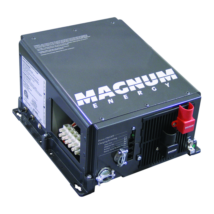
Energy. The ME Series is a “new generation” inverter designed especially for rugged recreational vehicle usage. Powerful, yet simple to use, the Magnum Energy inverter will provide you with years of trouble-free performance so you can enjoy the all of the comforts you have come to expect from your RV, all backed by our limited 3 year (36-month warranty). - Page 7 1. INTRODUCTION Figure 1 ME Series Inverter / Charger Ó 2003 - Magnum Energy, Inc. 2...
-
Page 8: How An Inverter/Charger Works
Your ME Series inverter has a built - in s a f e g u a r d t h a t automatically protects your batteries from over discharge. - Page 9 N e t P o r t R e m o t e Port Battery Temp Sensor Port Figure 2 ME Series Inverter / Charger Switch, LED and Connection Ports Figure 3 ME Series Inverter / Charger Electrical Connection Points...
-
Page 10: The Me Series Inverter/Charger
1. INTRODUCTION 5. The ME Series Inverter/Charger The ME Series inverter/charger is designed to allow easy access to wiring, circuit breakers, controls and LED status indicator. Its die cast baseplate with one piece aluminum cover ensures maximum durability with minimum weight, as well as cooler more efficient operation. The inverter is equipped with the following features: ON / OFF Switch - used to manually switch the inverter ON and OFF. -
Page 11: Installation
If items appear to be missing or damaged, contact Magnum Energy at (425) 353-8833 or your authorized Magnum Energy dealer. If at all possible, retain the shipping container in the event the unit ever needs to be returned for factory service. -
Page 12: Hardware / Materials Required
, D O N O T ground them at the safety ground. Ground them only at the negative bus of the DC load center (as applicable). Ó 2003 - Magnum Energy, Inc. 8... -
Page 13: Torque Requirements
G r o u n d w i r i n g f r o m t h e i n v e r t e r t o a n e x t e r n a l v e h i c l e g r o u n d Ó 2003 - Magnum Energy, Inc. -
Page 14: Installation
2. INSTALLATION M o u n t i n g S c r e w P l a c e m e n t s Figure 4 ME Series Inverter / Charger Base Plate Inverter ME1512 ME2012 ME2512 ME3012 DC Rating... - Page 15 Ó 2003 - Magnum Energy, Inc.
-
Page 16: Inverter Mounting
DO NOT mount the b a t t e r i e s d i r e c t l y u n d e r t h e i n v e r t e r . Secure the batteries to the mounting surface with battery hold down clamps. Ó 2003 - Magnum Energy, Inc. -
Page 17: Battery Cables And Sizing
’ s p o s i t i v e t e r m i n a l D O N O T c o n n e c t t h e p o s i t i v e c a b l e t o t h e i n v e r t e r a t t h i s time. Ó 2003 - Magnum Energy, Inc. -
Page 18: Parallel Connection
. Nut - Washer - Lug - Terminal - Washer - Bolt Nut - Washer - Lug - Inverter Terminal Figure 5 Figure 6 Battery Hardware Installation Inverter Hardware Installation Ó 2003 - Magnum Energy, Inc. - Page 19 2. INSTALLATION > TO 12 VDC 12 VDC 12 VDC 12 VDC 12 VDC INVERTER > Figure 7 Parallel Battery Wiring individual battery capacity = 100 AHr @ 12 VDC combined battery capacity = 400 AHr @ 12 VDC > Figure 8 Series Battery Wiring individual battery capacity = 200 AHr @ 6 VDC combined...
- Page 20 = 400 AHr @ 12 VDC Ó 2003 - Magnum Energy, Inc.
-
Page 21: Series Connection
Once the batteries are completely wired and tested, coat the terminals with an a p p r o v e d a n t i- o x i d i z i n g s p r a y . Ó 2003 - Magnum Energy, Inc. - Page 22 Series Battery Wiring - Fuse Placement > In - l i n e f u s e > 6 VDC 6 VDC 6 VDC 6 VDC TO 12 VDC INVERTER Figure 12 Series/Parallel Battery Wiring - Fuse Placement > Ó 2003 - Magnum Energy, Inc.
-
Page 23: Dc Fuse Block
2. INSTALLATION 3. Installation, continued DC Fuse Block A fuse or circuit breaker must be located within 18 inches of the battery to protect the DC wiring system. The device must be rated to match the size of the cable, but can be rounded up to the next larger size (i.e., a cable rated at 150 amps can accept a 175 amp fuse) as necessary. - Page 24 Ó 2003 - Magnum Energy, Inc.
-
Page 25: Ac Wiring
A C O u t p u t 1 C i r c u i t B r e a k e r (on dual output models only) Figure 14 ME Series Inverter / Charger - AC Wiring (Access Panel) Ó 2003 - Magnum Energy, Inc. -
Page 26: Ac Input (Shore Power) Routing
. The minimum wire size for all ME Series models must be #10 AWG. The i n s t a l l e r m u s t p r o v i d e t h e a p p r o p r i a t e c i r c u i t p r o t e c t i o n f o r t h e w i r e s i z e u s e d . - Page 27 2. INSTALLATION Figure 15 ME Series Inverter / Charger - AC Wiring Diagram ( l o c a t e d o n b a c k o f c o v e r p l a t e )
-
Page 28: Wiring The Inverter Ac Input
Replace the covers on the main electrical / distribution panel. Replace t h e chassis access cover. Verify the inverter’s front panel switch is in the "OFF" position. NOTE: If required by code, have the installation inspected by an electrical inspector. Ó 2003 - Magnum Energy, Inc. - Page 29 Typical Wiring - Single IN / Single OUT (120 VAC) Figure 18a Typical Wiring - Single IN / Dual OUT (120 VAC) Figure 19a Typical Wiring - Dual IN / Dual OUT (120 VAC / 240 VAC) Ó 2003 - Magnum Energy, Inc.
- Page 30 Typical Wiring - Single IN / Single OUT (120 VAC) Figure 18b Typical Wiring - Single IN / Dual OUT (120 VAC) Figure 19b Typical Wiring - Dual IN / Dual OUT (120 VAC / 240 VAC) Ó 2003 - Magnum Energy, Inc.
- Page 31 Stack Port M a g n u m N e t P o r t R e m o t e Port Battery Temp Sensor Port Figure 20 ME Series Inverter / Charger - Option Connection Ports Ó 2003 - Magnum Energy, Inc.
-
Page 32: Options
2. INSTALLATION 4. Options Battery Temperature Sensor Installation and Wiring Attach the ring terminal end of the Battery Temperature Sensor to the negative battery terminal. R o u t e t h e s e n s o r ’ s c a b l e t o t h e i n v e r t e r f o l l o w i n g e x i s t i n g w i r e r u n s . Connect the cable to the BTS port on the inverter’s chassis. - Page 33 Ó 2003 - Magnum Energy, Inc.
-
Page 34: Start-Up And Test
INVERTER to AC IN (SHORE POWER). Use a true RMS multimeter to verify 120 VAC at each of the coach’s AC outlets. Switch the Shore Power OFF. Verify the inverter’s LED switches to inverter mode. Ó 2003 - Magnum Energy, Inc. 2. INSTALLATION... -
Page 35: Configuring The Inverter
Shore Power Current, Charger Amps, Battery Size and Battery Type. These operational parameters must be configured using the optional remote control. Refer to the ME Series Remote Control operator’s manual to configure the following parameters: Shore (5, 10, 15, 20, 30, 50) - Page 36 Table 5 - Factory Default Settings Function Default Search 5 watts 11 LBCO Battery Bank Battery Type Liquid Lead Acid Charge Rate 100 % Contr a s t 75 % Ó 2003 - Magnum Energy, Inc.
-
Page 37: Operation
3. OPERATION C h a r g i n g / I n v e r t i n g Figure 21 ME Series Inverter / Charger - LED Indicator Ó 2003 - Magnum Energy, Inc. -
Page 38: Operating The Inverter
( f a s t f l a s h ) t o i n d i c a t e a b s o r p t i o n charging for 1 - 3 hours depending upon battery bank selection (refer to the ME Series Remote manual). The charger then switches to its final charging mode. - Page 39 3. OPERATION Figure 22 ME Series Inverter / Charger - Fault Conditions Figure 23 Optional ME Series Remote Control - Fault Conditions Ó 2003 - Magnum Energy, Inc.
-
Page 40: Fault Or Alarm Conditions
. T h e i n v e r t e r ’ s L E D t u r n s O F F t o i n d i c a t e t h e f a u l t c o n d it i o n . Ó 2003 - Magnum Energy, Inc. -
Page 41: Troubleshooting
Charger doesn’t charge. Loose or corroded battery cables. Clean and tighten battery cables. Defective batteries. Replace batteries. Wrong charger settings. Adjust the charger settings. Wrong AC input voltage. Verify proper AC input voltage and frequency. Ó 2003 - Magnum Energy, Inc. -
Page 42: Preventive Maintenance
R e m o v e s h o r e p o w e r a n d d i s a b l e t h e g e n e r a t o r ( i f i n s t a l l e d ) Ó 2003 - Magnum Energy, Inc. -
Page 43: Specifications
15,000 feet (4.57 km) Dimensions (HxWxD): 13.75” x 12.65” x 8” (34.9 cm x 32.1 cm x 20.3 cm) Mounting: shelf (top or bottom up) or bulkhead Specifications @ 25 °C - Subject to change without notice 2003 - Magnum Energy, Inc. Ó... -
Page 44: Warranty
5. The original purchaser shall return the product prepaid to Magnum Energy in Eve r e t t , W A . Magnum Energy will return the product prepaid to the original purchaser after the completion of service under this limited warranty. - Page 45 Remote Control for ME Series Inverter/Chargers Operator’s Manual...
- Page 46 Remote Control for ME Series Inverter/Chargers Table of Contents Section Page 1. Overview 2. Installation 3. Operation F r o n t P a n e l Rotary Knob Switches Chart 1 - Battery Charge Voltages Chart 2 - A b s orption Times...
-
Page 48: Overview
Use insulated tools Remote Control for ME Series Inverter/Chargers Congratulations on your purchase of a remote control for your Magnum Energy inverter/charger. The remote allows you to customize the operating parameters of the inverter/charger, t h u s m a x i m i z i n g p e r f o r m a n c e a n d i n c r e a s i n g t h e l i f e o f y o u r batteries. -
Page 49: Installation
2. Installation Installing the ME Series Remote Control 1. Determine a suitable location to mount the remote control. It must be located in a clean, dry and protected place. Allow ample room to access the remote’s adjustment dial and to v i e w t h e L E D s f o r t r o u b l e s h o o t i n g . -
Page 50: Operation
3. Operation Figure 2 Remote Control - Font Panel Ó 2003 - M a g n u m E n e r g y , I n c . -
Page 51: Rotary Knob
3. Operation, continued ME Series Remote Control - Front Panel The remote control is equipped with a wide range of easy-touse switches and displays, allowing you to quickly setup your inverter/charger as well as determine its operational status. Rotary Knob The Rotary “spin”... -
Page 52: Chart 1 - Battery Charge Voltages
Liquid Lead Acid (Flooded) Bulk Absorption Float Equalize 14.6 VDC 1 4 . 6 V D C 1 3 . 4 V D C 15.5 VDC Bulk Absorption Float Equalize 1 4 . 1 V D C 1 4 . 1 VD C 1 3 . -
Page 53: Chart 2 - Absorption Times
Chart 2 - Absorption Times (determined by battery bank size selection) Chart 3 - Factory Default Settings Ó 2003 - M a g n u m E n e r g y , I n c . Battery Size 200 Charge Time 90 AHr 400 AHr minutes 120... - Page 54 Options in clude FET temp, transformer temp, and battery temp. Factory Reset Restores all settings to factory defaults. press and hold the switch the switch for 5 seconds. “Reset Complete” will be appear in the display. See Chart 3. Ó 2003 - Magnum Energy, Inc.
-
Page 55: Leds
Shore or generator AC power is passed through the inverter to the loads. If shore or generator power is lost, the inverter automatically supplie s A C power to the loads. Ó 2003 - Magnum Energy, Inc. -
Page 56: Lcd Display
The DC current will start to taper off in order to maintain the bulk voltage setting. Absorption time is determined by battery bank size selection. See Chart 2. Figure 3 Menu Map Ó 2003 - Magnum Energy, Inc. Shore METER SETUP TECH... - Page 57 See Chart 1. Battery Saver - “Battery Full” Battery saver mode is a new and unique setting to Magnum Energy’s inverter/chargers. It maintains the batteries without “overcharging” thus preventing excessive loss of water in flooded batteries or drying out of AGM batteries.
-
Page 58: Troubleshooting And Specifications
(9.5 cm H x 16.6 cm W x 2.9 cm D) Cutout Dimensions 2.75" H x 4.75" W (7 cm H x 12 cm W) Specifications at 25 °C - subject to change without notice. 2003 - Magnum Energy, Inc. Ó... -
Page 59: Warranty
5. Warranty 36 Month Limited Warranty Magnum Energy, Inc., warrants the ME Series Remote Control to be free from defects in material and workmanship that result in product failure during normal usage, according to the following terms and conditions: 1. The limited warranty for the product extends for 36 months beginning from the product's original date of purchase. - Page 60 Magnum Service Manual REV 1.0 12/03 INDEX Troubleshooting Repairing 2.1 Top Cover Removal 2.2 AC Board 2.3 AC Breakers 2.4 Fet Board 2.6 DC Terminal Plate 2.7 Transformer 2.8 Fans 2.9 Remote Test Procedure...
-
Page 61: Troubleshooting
1.0 TROUBLESHOOTING 1.1 ME SERIES 1.2 SERIES REMOTE... - Page 62 2.0 REPAIRING OVERVIEW...
- Page 64 1.1 TOP COVER REMOVAL 2.1.a Top cover is attached with 6 - #10 x 5/8 Torx screws (#25 bit) and 1- #6 x 1/2 Torx screw (#15 bit). Remove all seven screws and pull straight up to remove top cover. 2.2.a Remove top cover per 2.1 2.2.b...
- Page 65 wires can lead to instant FET board failure upon connecting ac power to the unit. WIRING COLOR CODE: White – Neutral (2 wires) Black – AC Hot 1 Red – Hot 2 Blue – Hot 2.2.e Install wires to new ac board and install 4- #6 x ½ Torx screws. 2.2.f Use silicon to glue down sensors to transformer in old location.
- Page 66 2.3 AC BREAKERS 2.3.a Remove top cover per 2.1 2.3.b Remove 4- #6 x ½ Torx screws from corners of ac board and lift board slightly (see 2.2 for screw location) 2.3.c Loosen knurled nut on breaker shaft and pull breaker out 2.3.d Reinstall new breaker in reverse order 2.3.e Reinstall Top Cover...
- Page 67 2.4.e Install new control board in reverse order making sure to line up connector on board edge with FET board connector before pushing down on control board. 2.4.f Re-install Top Cover 2.5.a Remove top cover per 2.1 2.5.b Remove 2- ¼ x 20 bolts and nuts from inside DC plate 2.5.c Remove 2- #10 x ¾...
- Page 68 2.6 FET BOARD 2.6.a Remove top cover per 2.1 2.6.b Remove control board per 2.4 2.6.c Remove DC Plate per 2.5...
- Page 69 2.6.d Remove 2 - ¼ x 20 bolts and nuts from FET board wiring bundles to transformer lugs 2.6.e Remove 1 - #6 x ½ Torx screw from outside edge of FET board and unplug fan connectors 2.6.f Remove 4 - #10 x ¾ Torx screws from FET bar clamps 2.6.g Pull up firmly on FET board to release from base and remove black insulation material (Burquist)
- Page 70 Use a utility knife or sharp chisel to cut temp sensor loose then 2.7.c clean remaining silicon from transformer 2.7.d Remove 4 corner Phillips head screws holding down transformer 2.7.e Install new transformer being careful to align #10 nylon shoulder washers into base while setting transformer in place.
- Page 71 2.6 FANS 2.8.a Remove Top Cover per 2.1 2.8.b Remove 1 - #6 x ½ Torx screw from fan bracket 2.8.c Bend fan bracket upward to remove fan 2.8.d Reinstall fan in reverse order 2.8.e Reinstall Top Cover...
- Page 72 2.9 REMOTE 2.8.a Remove front knob (it may be necessary to pry slightly up on knob) 2.8.b Remove 2 Phillips head screws from back of remote 2.8.c Remove circuit board and keypad from case 2.9.d Re-assemble in reverse order...
Need help?
Do you have a question about the ME Series and is the answer not in the manual?
Questions and answers