Table of Contents
Advertisement
Advertisement
Table of Contents
Troubleshooting

Related Manuals for Magnum Energy MS Series


Summary of Contents for Magnum Energy MS Series
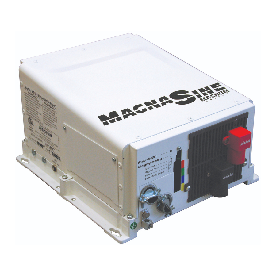
- Page 1 MS Series Pure Sine Wave Inverter/Charger Owner’s Manual...
-
Page 2: Contact Information
Restrictions on Use The MS Series Inverter/Charger shall not be used in connection with life support systems, life saving or other medical equipment or devices. Using the MS Series Inverter/Charger with this particular equipment is at your own risk. -
Page 3: Important Safety Instructions
IMPORTANT SAFETY INSTRUCTIONS • This manual contains important safety instructions that must be followed during the installation and operation of this product. • All electrical work must be performed in accordance with local, state and federal electrical codes. • Read all instructions and safety information contained in this manual before installing or using this product. - Page 4 IMPORTANT BATTERY SAFETY INSTRUCTIONS • Be very careful when working around batteries, they can produce extremely high currents if short-circuited. Read the battery supplier’s precautions before installing the inverter and batteries. • Wear eye protection such as safety glasses when working with batteries. •...
-
Page 5: Table Of Contents
Table of Contents Introduction ..................1 Features and Benefi ts ................. 2 How an Inverter/Charger Works ..............5 Advantages of a Pure Sine Wave vs Modifi ed Sine Wave Inverter ...... 5 Appliances and Run Time ................6 Installation ...................7 Pre-Installation ..................7 Mounting the Inverter ................10 Wiring the Inverter - General Requirements ..........12 DC Wiring ....................13... - Page 6 Figure 2-7, Battery Temperature Sensor ..................18 Figure 2-8, MS Series Inverter/Charger - AC Wiring ............... 21 Figure 2-9, MS Series Inverter/Charger - AC Wiring (Access Panel) ..........21 Figure 2-10, AC Terminal Block ..................... 22 Figure 2-11, AC Wiring for Single In - Single Out (30 A) Confi gurations ..........25 Figure 2-12, AC Wiring for Single In - Single Out (60 A) Confi...
-
Page 7: Introduction
Congratulations on your purchase of the MS Series inverter/charger from Magnum Energy. The MS Series is a “pure” sine wave inverter designed especially for rugged mobile applications, home backup power and stand-alone applications. Powerful, yet simple to use, this inverter/charger will provide you with years of trouble-free performance you have come to expect from Magnum Energy. -
Page 8: Features And Benefi Ts
The front of the MS Series is equipped with the following features (see fi gures 1-1 and 1-2): • (1) Power Switch - a momentary push-button switch that alternately turns the inverter ON or OFF. -
Page 9: Figure 1-1, Power Switch, Status Led And Accessory Connection Ports
Introduction Power ON/OFF Switch Status LED (Charging/Inverting) Stacking/Accessories Port (red label) Magnum Net Port (green label) Remote Port (blue label) Battery Temp Sensor Port (yellow label) Figure 1-1, Power Switch, Status LED and Accessory Connection Ports Intake Air Vents (and on right side) (10) Positive (+) AC Entry/Exit... -
Page 10: Figure 1-3, Left Side Features
Introduction The left side of the MS Series is equipped with the following features (see to fi gure 1-3): • (13) Exhaust Air Vent - ventilation openings that allow heated air to be removed by the internal cooling fan. •... -
Page 11: How An Inverter/Charger Works
The MS Series is built on the same platform as our popular ME and RD Series modifi ed sine wave inverters allowing for an easy upgrade from the original ME or RD Series installation. This standard platform also helps reduce cost by using standard parts/accessories across many models. -
Page 12: Appliances And Run Time
Your MS Series inverter has a built-in safeguard that automatically protects your batteries from over discharge. -
Page 13: Installation
MS inverter/charger. The more thorough you plan in the beginning, the better your inverter needs will be met. 2.1.1 Unpacking and Inspection Carefully remove the MS Series inverter/charger from its shipping container and inspect all contents. Verify the following items are included: • The MS Inverter/Charger •... -
Page 14: Figure 2-1, Simplifi Ed Installation Diagram For Permanent Installations
Installation G e n e ra to r P o w e r U tility P o w e r 1 2 0/2 4 0 V A C O u tp u t 1 2 0/2 4 0 V A C O u tp u t M E -A G S - N A u to G en S tart C o n tro ller... - Page 15 fl ammable liquids like gasoline or propane, or in locations that require ignition-protected devices. WARNING: The MS Series inverter/charger is not ignition protected and may not be located in an engine compartment with gasoline-fueled engines under any circumstance.
-
Page 16: Mounting The Inverter
This surface and the mounting hardware must also be capable of supporting at least twice the weight of the inverter. To meet regulatory requirements, the MS Series must be mounted in one of the following positions; as shown in fi gure 2-2: •... -
Page 17: Figure 2-3, Ms Series Dimensions
Installation 8" 6 5/8" 12" Keyhole 13 3/4" slots (x4) 4 7/8" mounting holes (x4) accept up to 9/32" 2" screw/ bolt 4 7/8" 12 5/8" Figure 2-3, MS Series Dimensions © 2009 Magnum Energy Inc. Page 11... -
Page 18: Wiring The Inverter - General Requirements
Installation Wiring the Inverter - General Requirements This section also describes the requirements and recommendations for wiring the MS Series inverter/charger. Before wiring the MS Series inverter/charger, read all instructions. All wiring should meet all local codes and standards and be performed by qualifi ed personnel such as a licensed electrician. -
Page 19: Dc Wiring
Installation DC Wiring This section describes the inverter’s required DC wire sizes and the recommended disconnect/ overcurrent protection and how to make the DC connections to the inverter and the battery bank. Refer to fi gure 2-4 when connecting the DC wires. WARNING: Even though DC voltage is “low voltage”, signifi... -
Page 20: Figure 2-4, Dc And Battery Temperature Sensor Wiring
Installation M S S e rie s In v e rte r/C h a rg e r w all m ounted view front view M E-CB Conduit Box Inv e rte r’s D C P os itiv e C a ble Inv e rte r’s D C N e ga tiv e C a ble B a tte ry Te m p S e ns or C a ble Inv e rte r’s D C E quipm e nt... -
Page 21: Table 2-1, Recommended Dc Wire/Overcurrent Device For Rated Use
Installation 2.4.1 DC Wire Sizing It is important to use the correct DC wire to achieve maximum effi ciency from the system and reduce fi re hazards associated with overheating. Always keep your wire runs as short as practical to help prevent low voltage shutdowns and keep the DC breaker from nuisance tripping (or open fuses) because of increased current draw. -
Page 22: Figure 2-5, Battery Hardware Installation
Installation Table 2-2, DC Wire Size For Increased Distance Minimum Recommended DC Wire Size (one way)* Inverter 5 feet or less 5 to 10 feet 10 to 15 feet Model In Conduit In free air In Conduit In free air In Conduit In free air MS2012... - Page 23 3) the correct DC voltage and polarity have been verifi ed. Info: For the MS Series inverter/charger to perform optimally, a minimum battery bank of 200 AH is recommended for moderate loads (<1000W) and greater than 400 AH for heavy loads (≥1000W).
-
Page 24: Figure 2-7, Battery Temperature Sensor
Installation 2.4.6 Battery Temperature Sensor Installation and Wiring The Battery Temperature Sensor (shown in fi gure 2-7) provides the inverter with precise battery temperature information to automatically adjust the ABSORB and FLOAT charge voltage setpoints This allows the batteries to be correctly charged under extreme temperature changes. If the temperature sensor is NOT installed and if the batteries are subjected to large temperature changes, the battery life may be shortened. - Page 25 Installation 2.4.7 Wiring the Inverter to the Battery Bank CAUTION: Inverter is NOT reverse polarity protected, if this happens the inverter will be damaged and will not be covered under warranty. Before connecting the DC wires from the batteries to the inverter, verify the correct battery voltage and polarity using a voltmeter.
-
Page 26: Ac Wiring
AC circuits. The MS Series provides a terminal block (see fi gure 2-10) that allows the AC input and output wiring to be permanently wired. This terminal block allows a service/distribution panel (main panel) to be wired to the inverter’s input and a dedicated panel (sub-panel) -
Page 27: Figure 2-8, Ms Series Inverter/Charger - Ac Wiring
AC Output 2 Circuit Breaker (CB2) (on -15B, -20B output breaker models only) AC Output 1 Circuit Breaker (CB1) (on -15B, -20B output breaker models only) Figure 2-9, MS Series Inverter/Charger - AC Wiring (Access Panel) © 2009 Magnum Energy Inc. Page 21... -
Page 28: Figure 2-10, Ac Terminal Block
Installation 2.5.3 Recommended GFCI (Ground Fault Circuit Interruption) Breakers Some electrical safety codes require the use of GFCI’s. In compliance with UL standards, Magnum Energy has tested the following GFCI’s and fi nd that they function properly when connected to the inverter’s AC output: Shock Sentry #XGF15V-SP... - Page 29 Installation 2.5.5 AC Conductor Wiring The following steps are basic guidelines for installing and connecting the AC wiring into and out of the inverter, refer to table 2-3 to determine your AC wiring confi gurations before beginning. WARNING: Before making any AC connections, make sure the inverter is disconnected from the battery and all AC power is disconnected from the inverter.
-
Page 30: Table 2-3, Ac Input/Output Wiring Confi Gurations
Installation 2.5.5 AC Wiring Confi gurations The following table provides the different wiring confi gurations for installing and connecting the AC conductors into and out of the inverter (refer to fi gures 2-11 to 2-15 for installation drawings showing these confi gurations). Table 2-3, AC Input/Output Wiring Confi... -
Page 31: Figure 2-11, Ac Wiring For Single In - Single Out (30 A) Confi Gurations
Installation A C T e rm in a l B lo c k ( A C in p u t a n d o u tp u t w irin g ) M S S e rie s In v e rte r A C G R O U N D S (to /from both P a ne ls) -
Page 32: Figure 2-12, Ac Wiring For Single In - Single Out (60 A) Confi Gurations
Installation A C T e rm in a l B lo c k ( A C in p u t a n d o u tp u t w irin g ) M S S e rie s In v e rte r A C G R O U N D S (to /from both P a ne ls) -
Page 33: Figure 2-13, Ac Wiring For Single In - Dual Out Confi Gurations
Installation A C T e rm in a l B lo c k ( A C in p u t a n d o u tp u t w irin g ) M S 2 0 1 2- 1 5 B o r M S 2 0 1 2 -2 0 B In v e rte r A C G R O U N D S (to /from both... -
Page 34: Figure 2-14, Ac Wiring For Dual In - Single Out Confi Gurations
Installation A C T e rm in a l B lo c k ( A C in p u t a n d o u tp u t w irin g ) M S S e rie s In v e rte r A C G R O U N D S (to /from both P a ne ls) -
Page 35: Figure 2-15, Ac Wiring For Dual In - Dual Out Confi Gurations
Installation A C T e rm in a l B lo c k ( A C in p u t a n d o u tp u t w irin g ) M S S e rie s In v e rte r A C G R O U N D S (to /from both P a ne ls) -
Page 36: Grounding Inverters
The MS Series inverter/charger uses both AC and DC power; however the AC electrical system is isolated from the DC electrical system by an internal transformer. Although this inverter/charger has two electrical systems, each electrical system must be properly grounded and connected to a common “earth”... -
Page 37: Figure 2-17, Multiple Connections To Dc Ground Rod (Method 1)
Installation 2.6.1 Sizing the Grounding Electrode Conductors AC Side - The size of the AC Grounding Electrode Conductor (GEC –AC) depends on the size of the largest ungrounded conductor feeding the AC load center. One #8 AWG (8.4 mm ) copper conductor will serve as an AC Grounding Electrode Conductor (GEC –AC) for AC power conductors smaller than and including #2 AWG (33.6 mm ) copper. -
Page 38: Figure 2-18, Multiple Connections To Dc Ground Rod (Method 2)
Installation Method 2 (see fi gure 2-18): When the AC and DC service panels are near each other, then the AC Grounding Electrode Conductor (GEC – AC) and DC Grounding Electrode Conductor (GEC – DC) can be connected to a single Grounding Electrode. In this method - since there are multiple connections to the DC Grounding Electrode (GEC –... -
Page 39: Table 2-5, Equipment Grounding Conductor Sizing
2.6.2 System Bonding Jumper The MS Series inverter does not include an internal bond between the Grounded Conductor (AC neutral/DC negative) and the equipment grounding terminals. This bond [System Bonding Jumper (SBJ)] is usually done in the main distribution panel for each electrical system. - Page 40 (shown in fi gure 2-20). The DC ground terminal on the MS Series must also be connected to the boats safety ground bus. This ensures that both the inverters AC and DC ground terminals are connected to the boats safety ground bus as a safety measure to provide protection against faults and provide a path for AC fault currents while the boat is connected to shore power.
-
Page 41: Figure 2-20, Neutral-To-Ground Connection (Inverter Mode)
AC source (i.e. shore power or a generator) is qualifi ed, another neutral-to-ground connection is introduced in the system. When the MS Series is connected to this external AC source and goes into Standby Mode, the internal relay automatically opens the neutral-to-ground connection as shown in fi... -
Page 42: Figure 2-22, Disconnecting The Ground-To-Neutral Connection
2.6.6 Disabling the Neutral-to-Ground Connection All MS Series Inverter/Chargers have the automatic neutral-to-ground switching feature. In some installations/jurisdictions, this feature must be disabled. If you are not sure whether you must disable this feature, check your local code requirements. The following steps will guide you in disabling the neutral-to-ground switching feature in the MS Series inverter/charger. -
Page 43: Inverter Notifi Cation Requirements
Installation Inverter Notifi cation Requirements When an inverter is installed in a building, facility or structure, the NEC (National Electrical Code) requires a label or plaque to be provided. This label/plaque is required to be easily visible and provide information that informs personnel on the location of all electrical system disconnects. This is to ensure all power to a building is quickly located and shutdown in an emergency. -
Page 44: Functional Test
Installation Functional Test After all electrical connections to the inverter, batteries, AC source, and sub-panel have been completed; follow these steps to test the installation and the inverter operation. CAUTION: Use a multimeter to verify the correct DC voltage for your particular inverter model (i.e., 24-volt battery bank for a 24-volt inverter) and ensure the polarity of the battery voltage is correct (battery positive connected to inverter positive terminal and negative battery connected to inverter negative terminal). -
Page 45: Operation
5 to 50 watts using the ME-RC remote display. Inverting - When a load greater than 5 watts is connected to the inverter output, the MS Series “inverts” the DC power from the battery and supplies 120 VAC power to your sub-panel The inverter’s green LED fl... -
Page 46: Standby Mode
Operation Standby Mode The MS Series features an automatic transfer relay and an internal battery charger when operating in the Standby Mode. The Standby Mode begins whenever AC Power (Utility or Generator) is connected to the inverter’s AC input. Once the AC voltage and frequency of the incoming AC power is within the AC input limits, an automatic AC transfer relay is activated. -
Page 47: Figure 3-3, Automatic 4-Stage Charging Graph
24.2 VDC on 24-volt models) or lower, the unit will begin another Bulk charge. * These settings in the MS Series are changeable and leave the factory with default values (see Table 3-2, Inverter/Charger Default Values). These default values are adequate for most installations, however, if you determine that some of the values need to be changed for your particular system, the ME-RC50 remote control may be purchased to adjust these settings. -
Page 48: Transfer Time
The transfer from Standby mode to Inverter mode occurs in approximately 16 milliseconds. While the MS Series is not designed as a computer UPS system, this transfer time is usually fast enough to hold them up. However, the VAC dropout setting has an effect on the ability of the loads to transfer without resetting. -
Page 49: Protection Circuitry Operation
Operation Protection Circuitry Operation The inverter is protected against fault conditions and in normal usage it will be rare to see any. However, if a condition occurs that is outside the inverter’s normal operating parameters, then it will shut down and attempt to protect itself, the battery bank, and your AC loads. If there is a condition that causes the inverter to shutdown, it may be one of the following conditions [also refer to the Troubleshooting section (Section 4.3) to help diagnose and clear the fault condition]. -
Page 50: Inverter Startup
Operation Inverter Startup ON/OFF Switch - The inverter can be turned on and off by lightly pressing and releasing the Power ON/OFF switch on the front of the inverter (refer to fi gure 3-5). When the inverter is fi rst connected to the batteries, or when its automatic protection circuit has turned the inverter off, the ON/OFF switch will need to be pressed to start the unit (or reset per section 4.4). -
Page 51: Factory Default Values
Operation Factory Default Values Your MS Series inverter/charger uses default values for the adjustable settings (shown in Table 3-2) that are adequate for most installations. If some of your operating parameters need to be changed from the default values, the optional ME-RC remote control can be used to make those changes. -
Page 52: Maintenance And Troubleshooting
Maintenance and Troubleshooting 4.0 Maintenance and Troubleshooting The following information is provided to help you keep your MS Series Inverter/Charger in optimum operational condition. Recommended Inverter and Battery Care The MS Series inverter/ charger is designed to provide you with years of trouble-free service. -
Page 53: Troubleshooting
Maintenance and Troubleshooting Troubleshooting The MS Series inverter/charger is a fairly simple device to troubleshoot. There are only two active circuits (AC and DC) as well as a charging circuit. The following chart is designed to help you quickly pinpoint the most common inverter failures. -
Page 54: Resetting The Inverter
Maintenance and Troubleshooting Resetting the Inverter Under some fault conditions (i.e., an ‘internal’ fault), the inverter will need to be reset. To reset the inverter: Press and hold the Power ON/OFF pushbutton (see fi gure 4-1) for approximately fi fteen (15) seconds until the Charging/Inverting Status LED comes on and fl... -
Page 55: Appendix A - Specifi Cations And Optional Equipment
Appendix A - Specifi cations Appendix A - Specifi cations and Optional Equipment A-1 Inverter/Charger Specifi cations MS2012 (-15B, -20B) MS2812 MS4024 Inverter Specifi cations Input battery voltage range 9.0 to 16.8 VDC 9.0 to 16.8 VDC 18.0 to 33.6 VDC Absolute maximum DC input 25 VDC 25 VDC... -
Page 56: Inverter Effi Ciency
Appendix A - Specifi cations Inverter Effi ciency The following curves are plotted to show the MS Series effi ciency over the full power range and is displayed as a percentage. This graph represents the inverter’s effi ciency while operating resistive loads. -
Page 57: Optional Equipment And Accessories
Appendix A - Specifi cations A-4 Optional Equipment and Accessories The following Magnum Energy components are available for use with the MS Series inverter/Charger. Some of these items are required depending upon the intended use of the inverter. A-4.1 Automatic Generator Start (AGS) Controller The Magnum Auto Gen Start controller is designed to automatically start your generator based on low battery condition or high temperature. -
Page 58: Appendix B - Battery Information
AC utility or generator power. Info: For the MS Series inverter/charger to perform optimally, a minimum battery bank of 200 AH is recommended for moderate loads (<1000W) and greater than 400 AH for heavy loads (≥1000W). -
Page 59: Battery Bank Sizing Worksheet
Appendix B - Battery Information B-5 Battery Bank Sizing Worksheet Complete the steps below to determine the battery bank size required to power your AC loads: 1. Determine the daily power needed for each load a) List all AC loads required to run; and b) List the Watt-Hours for each load (see table B-1 for common loads/wattage);... -
Page 60: Battery Wiring Confi Gurations
Appendix B - Battery Information B-6 Battery Wiring Confi gurations The battery bank must be wired to match the inverter’s DC input voltage. In addition, the batteries can be wired to provide additional run time. The various wiring confi gurations are: B-6.1 Series Wiring Wiring batteries in series increases the battery bank’s output voltage. -
Page 61: Figure B-4, Battery Bank Wiring Examples (12-Volt)
Appendix B - Battery Information ov er - c urrent protec tion to 12 VDC to 12 V D C S trin g in verter inverter 12 V D C ( to tal cap acity (total capacity (1 2 V D C @ 1 0 0 A H) b attery = 100 A H ) = 100 AH) -
Page 62: Figure B-5, Battery Bank Wiring Examples (24-Volt)
Appendix B - Battery Information ov er - c urrent to 24 VDC to 24 V D C protec tion S e rie s S trin g inverter 12 V D C 12 V D C in verter b attery b attery (1 2 V D C + 1 2 V D C) (total capacity... -
Page 63: Limited Warranty
Appendix C - Warranty & Service Limited Warranty Magnum Energy, Inc., warrants the MS Series Inverter/Charger to be free from defects in material and workmanship that result in product failure during normal usage, according to the following terms and conditions: 1. - Page 64 Magnum Energy, Inc. 2211 West Casino Rd. Everett, WA 98204 Phone: 425-353-8833 Fax: 425-353-8390 Web: www.magnumenergy.com MS Series Owner’s Manual (PN: 64-0007 Rev A)
Need help?
Do you have a question about the MS Series and is the answer not in the manual?
Questions and answers