Magnum Energy MM Series Owner's Manual
Mm series
Hide thumbs
Also See for MM Series:
- Installation and operation manual (16 pages) ,
- Installation and operation manual (44 pages)
Table of Contents
Advertisement
Advertisement
Table of Contents

Related Manuals for Magnum Energy MM Series


Summary of Contents for Magnum Energy MM Series
- Page 1 MM Series Inverters Owner’s Manual...
-
Page 2: Contact Information
Restrictions on Use The MM Series Inverter shall not be used in connection with life support systems, life saving or other medical equipment or devices. Use of this particular equipment is at your own risk. -
Page 3: Save These Instructions
• No overcurrent protection for the AC output wiring is provided as an integral part of this inverter. Overcurrent protection of the AC output wiring must be provided as part of the system installation. SAVE THESE INSTRUCTIONS © 2010 Magnum Energy, Inc. - Page 4 In the event of exposure to the eyes, fl ood them for at least 15 minutes with running water and seek immediate medical attention. • Recycle old batteries. SAVE THESE INSTRUCTIONS © 2010 Magnum Energy, Inc.
-
Page 5: Table Of Contents
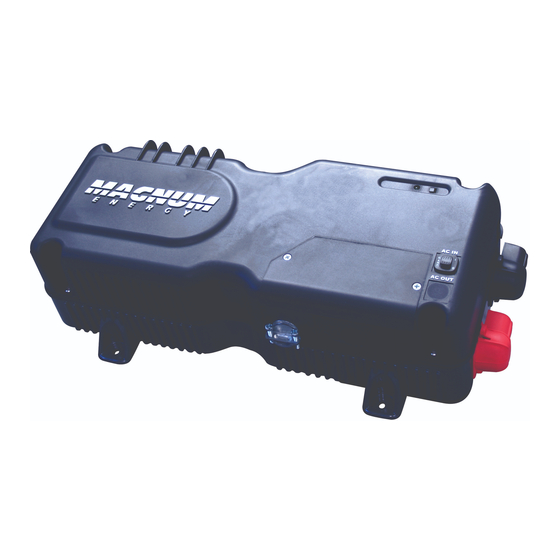
Table of Contents 1.0 Introduction ..............1 MM Series Models ..............1 How an Inverter/Charger Works ..........2 What Appliances will run from a Modifi ed Sine Inverter ....2 Appliances and Run Time ............2 Standard Features and Benefi ts ..........3 Battery Temperature Sensor .......... - Page 6 RV/Marine Off-Season Storage ..........35 Appendix D - Warranty/Service Information .....36 List of Figures Figure 1, MM Series Inverter ........... 1 Figure 2, Top Side Features ............. 3 Figure 3, Front and Back Side Features ........4 Figure 4, Left Side Features ............ 5 Figure 5, Battery Temperature Sensor (BTS) ......
-
Page 7: 1.0 Introduction
1.0 Introduction 1.0 Introduction Congratulations on your purchase of an MM Series inverter from Mag- num Energy, Inc. This product is designed to be powerful, yet simple to use, and provide you with years of trouble-free use. Please read this chapter to familiarize yourself with the features and benefi... -
Page 8: How An Inverter/Charger Works
AC power cord. Even though it is dif- fi cult to calculate exactly how long an inverter will run a particular ap- pliance, the best advice is trial and error. Your MM Series inverter has a built-in safeguard that automatically protects your batteries from being over-discharged. -
Page 9: Standard Features And Benefi Ts
1.0 Introduction Standard Features and Benefi ts The MM Series inverter converts 12 Volts Direct Current (VDC) power from your battery to 120 Volts Alternating Current (VAC) power. models with the multi-stage battery charger feature, the incoming AC power is optimized using Power Factor Correction (PFC) technology to keep the inverter’s battery bank fully charged. -
Page 10: Figure 3, Front And Back Side Features
14. Model/Serial Number label - includes model/serial number and provides specifi cations and information on the inverter and charger. See the Specifi cations on page 28 for more information and the dif- ferent models available. © 2010 Magnum Energy, Inc. -
Page 11: Battery Temperature Sensor
If the temperature sensor is NOT installed and the batteries are subjected to large temperature changes, the battery life may be shortened. ~1" ~2" FRONT VIEW ~¾” 0.375" diameter Cable SIDE VIEW ~½” Figure 5, Battery Temperature Sensor © 2010 Magnum Energy, Inc. -
Page 12: 2.0 Installation
Unpacking and Inspection Carefully remove the MM Series inverter from its shipping container and inspect all contents. Verify the following items are included: − The MM Inverter − Red and black DC terminal covers −... -
Page 13: Figure 6, Basic Installation Diagram
2.0 Installation MM Series Inverter AC IN Ground disconnect overcurrent device Main Panel Battery Bank Sub-Panel Tools AC Loads Outlet Figure 6, Basic Installation Diagram © 2010 Magnum Energy, Inc. -
Page 14: Locating And Mounting The Inverter
Safe - Keep any fl ammable/combustible material (e.g., paper, cloth, plastic, etc.) that may be ignited by heat, sparks, or fl ames at a minimum distance of 2 feet (60 cm) away from the inverter. © 2010 Magnum Energy, Inc. -
Page 15: Figure 7, Approved Mounting Orientations
Also allow enough room to access the AC and DC wiring connections, as they will need to be checked and tightened periodically. See Figure 8 for the MM Series’ inverter dimensions. Mounting Orientation - To meet regulatory requirements, the MM... -
Page 16: Wiring Guidelines
" (6.71") ~ 7 ½" (7.51") " (8.41") 7/16 Figure 8, MM Series Inverter Dimensions Wiring Guidelines • Before connecting any wires, determine all wire routes to and from the inverter throughout the RV or vehicle/boat. • Conductors passing through walls, bulkheads, or other structural members must be protected to minimize insulation damage such as chafi... -
Page 17: Dc Wiring
DC breaker from nuisance tripping (or open fuses) because of increased current draw. Undersized cables can also lower the inverter’s peak output voltage as well as reduce its ability to surge heavy loads. © 2010 Magnum Energy, Inc. -
Page 18: Table 1, Recommended Dc Wire/Overcurrent Device
Minimum recommended DC wire size (one way) 3 ft or less 3 to 5 ft 5 to 10 ft 10 to 15 ft MM612 #4 AWG #2 AWG #1/0 AWG #2/0 AWG MM1212 # 1 AWG #1/0 AWG #2/0 AWG recommended © 2010 Magnum Energy, Inc. -
Page 19: Dc Overcurrent Protection
If there are any non-factory installed DC appliances on board the vehicle, DO NOT ground them at the safety ground. Ground them only at the negative bus of the DC load center (as applicable). © 2010 Magnum Energy, Inc. -
Page 20: Dc Cable Connections
DC wires to the inverter’s DC terminals. DC cable with ring lug terminal cover (snaps on) Inverter’s DC terminal ½” Kep nut (nut with star-washer) Figure 10, DC Cable to Inverter’s DC Terminals © 2010 Magnum Energy, Inc. -
Page 21: Battery Bank Wiring
If necessary, color code the cables with colored tape or heat shrink tubing; RED for positive (+), and BLACK for negative (-) to avoid polarity confusion. © 2010 Magnum Energy, Inc. -
Page 22: Dc Ground Wire
Press on the red and black terminal covers to the inverter’s DC connec- tors to secure them in place. If batteries are in an enclosure, perform a fi nal check of the hold down brackets and all connections. Close and secure the battery enclosure. © 2010 Magnum Energy, Inc. -
Page 23: Ac Wiring
However, when an external AC source is connected, another neutral-to-ground connection is introduced in the system. When the MM Series is connected to this external AC source, the internal relay automatically opens the neutral-to-ground connection. This design keeps two neutral-to-ground connections from occurring at the same time. -
Page 24: Ac Wire Size And Overcurrent Protection
Wire Size Breaker Size Breaker Wire Size Breaker Size MM612 7 amps #14 AWG 10 amps 8 amps #14 AWG 10 amps MM1212 20 amps #12 AWG 20 amps 12 amps #14 AWG 15 amps © 2010 Magnum Energy, Inc. -
Page 25: Ac Input Wiring
3. Using approved AC wire connectors, connect the incoming Hot In, Neutral In, and Ground wires to the MM Series’ AC wires colored black (HOT IN), white (NEU IN), and green (AC GROUND) respectively. 4. After making the AC input connections, secure the AC input cable by tightening the strain relief. -
Page 26: Ac Output Wiring
5. Using approved AC wire connectors, connect the outgoing Hot Out, Neutral Out, and AC Ground wires to the MM Series’ AC wires colored red (HOT OUT), white with black stripe (NEU OUT), and green (AC GROUND) respectively. Gently pull on the wires to ensure they are securely held together, and check to see that no bare wire is exposed. -
Page 27: Functional Test
If the inverter passes all the steps, the inverter is ready for use. If the it fails any of the steps, refer to the Troubleshooting section. © 2010 Magnum Energy, Inc. -
Page 28: 3.0 Operation
3.0 Operation 3.0 Operation Operating Modes The MM Series inverter has two normal modes of operation; Invert Mode, which powers your loads using the batteries, and Transfer Mode, which powers your loads from the incoming AC power (i.e., shore pow- er or a generator). -
Page 29: Protection Mode
Charge Mode (not available on all models) Some MM Series models are equipped with a multi-stage battery charger feature. This includes an automatic 4-stage charging process: Bulk, Absorb, Float and Full Charge; and a manual charge stage: Equalization (the ME-RC50 is required to enable Equalization charge). - Page 30 BTS is below 77° F (25° C), and decrease if the temperature around the BTS is higher than 77° F (25° C). ** The MM Series uses changeable settings (see Table 5, Inverter Default Set- tings) that are adequate for most installations. However, if you determine that some of your operating parameters need to be changed, the ME-RC50 remote control can be purchased to allow changes to those settings.
-
Page 31: Start-Up
Some units are equipped with the internal battery charger – with this option the green LED status indicator provides additional infor- mation: • Blinks off every four seconds - The unit is charging the batteries connected to the inverter. © 2010 Magnum Energy, Inc. -
Page 32: Factory Default Settings
3.0 Operation Factory Default Settings Your MM Series inverter uses default settings that are adequate for most installations. However, if you determine that some of your oper- ating parameters need to be changed, the optional ME-RC50 remote allows you to control the operation and to customize the programming parameters of the inverter and/or charger. -
Page 33: 4.0 Troubleshooting
4.0 Troubleshooting 4.0 Troubleshooting The MM Series inverter is a fairly simple device to troubleshoot. There are only two active circuits (AC and DC) as well as a charging circuit in some of the models. The following chart is designed to help you quickly pinpoint the most common inverter and charger faults. -
Page 34: 5.0 Specifi Cations
5.0 Specifi cations 5.0 Specifi cations Table 7, MM Series Specifi cations MODEL MM612 MM1212 Inverter Specifi cations Input DC voltage range 9 to 15.5 Vdc Output voltage AC 120 VRMS +/- 5% Output frequency 60 Hz +/- .004% 1msec peak surge current... -
Page 35: Appendix A - Remote Control And Monitoring
MM-RC - Provides six LED indicators for inverter and charger status, includes a remote ON/OFF switch; comes with 25’ cable. This remote is for the MM Series inverter with the battery charger feature – the MM1212 model. ME-RC50 - Full feature remote with backlit LCD display and LED in- dicators for inverter and charger status. -
Page 36: On/Off Switch
The inverter will automatically turn on to power the AC loads if the external AC power is lost or disconnected. • Blinks On (once every second) - The inverter is in Search Mode. The AC load is below 5 watts (Search Watts default setting). © 2010 Magnum Energy, Inc. -
Page 37: Ac In (Green)
15 seconds, and then reconnect. After resetting the inverter, momentarily press the inverter’s ON/OFF switch and verify the fault has cleared. If the internal fault remains, the inverter requires service at an authorized repair facility. © 2010 Magnum Energy, Inc. -
Page 38: Mm-Rc Remote Only
BTS – this ensures correct charging. ** These settings are preset in the inverter (see Table 5, Inverter De- fault Settings), but can be changed using the ME-RC50 remote. © 2010 Magnum Energy, Inc. -
Page 39: Appendix B - Battery Information
– resulting in a 12 VDC/200 AHr bank. overcurrent protection 6 volts 6 volts 12 VDC (200 AHrs ) (200 AHrs ) Inverter 12 volt battery bank (total capacity = 200 AHrs) Figure 14, Series Battery Wiring © 2010 Magnum Energy, Inc. -
Page 40: Parallel Wiring
(200 AHrs ) protection String 1 6 volts 6 volts 12 VDC (200 AHrs ) (200 AHrs ) Inverter String 2 12 volt battery bank (total capacity = 400 AHrs) Figure 16, Series-Parallel Battery Wiring © 2010 Magnum Energy, Inc. -
Page 41: Appendix C - Preventive Maintenance
Appendix C - Preventive Maintenance Recommended Inverter and Battery Care The MM Series inverter is designed to provide you with years of trouble-free service. Even though there are no user-serviceable parts, it is recommended that every 6 months you perform the following maintenance steps to ensure optimum performance and extend the life of your batteries. -
Page 42: Appendix D - Warranty/Service Information
Appendix D - Warranty/Service Information 24 Month Limited Warranty Magnum Energy, Inc., warrants the MM Series Inverter to be free from defects in material and workmanship that result in product failure during normal usage, according to the following terms and conditions: 1. - Page 43 © 2010 Magnum Energy, Inc.
- Page 44 Magnum Energy, Inc. 2211 West Casino Rd. Everett, WA 98204 Phone: (425) 353-8833 Fax: (425) 353-8390 Web: www.magnumenergy.com PN: 64-0008 Rev B © 2010 Magnum Energy, Inc.
Need help?
Do you have a question about the MM Series and is the answer not in the manual?
Questions and answers