Table of Contents
Advertisement
Advertisement
Table of Contents

Related Manuals for Magnum Energy MS-PAE Series


Summary of Contents for Magnum Energy MS-PAE Series
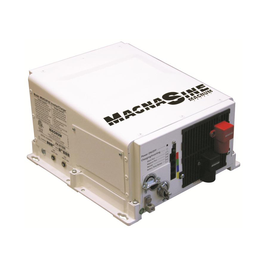
- Page 1 MS-PAE Series Pure Sine Wave Inverter / Charger Owner’s Manual...
-
Page 2: Contact Information
Since the use of this manual and the conditions or methods of installation, operation, use and maintenance of the MS-PAE Series Inverter/Charger is beyond the control of Magnum Energy Inc., this company does not assume responsibility and expressly disclaims liability for loss, damage or expense, whether direct, indirect, consequential or incidental, arising out of or anyway connected with such installation, operation, use, or maintenance. -
Page 3: Important Safety Instructions
IMPORTANT SAFETY INSTRUCTIONS • This manual contains important safety instructions that must be followed during the installa- tion and operation of this product. • All electrical work must be performed in accordance with local, state and federal electrical codes. • Read all instructions and safety information contained in this manual before installing or using this product. - Page 4 IMPORTANT BATTERY SAFETY INSTRUCTIONS • Wear eye protection such as safety glasses when working with batteries. • Remove all jewelry such as rings, watches, bracelets, etc., when installing or performing maintenance on the inverter. • Never work alone. Always have someone near you when working around batteries. •...
-
Page 5: Table Of Contents
Table of Contents Introduction 1.0 Introduction ......................1 1.1 Features and Benefi ts ..................... 3 1.2 How the MS-PAE Series Inverter/Charger Works ............5 Installation 2.0 Installation ......................6 2.1 Pre-Installation ..................... 6 2.2 Grounding Inverters ....................12 2.3 DC Wiring ......................16 2.4 AC Wiring ......................22... - Page 6 Figure 2-2, Approved Mounting Positions ................9 Figure 2-3, MS-PAE Series Dimensions ................10 Figure 2-4, Grounding System for MS-PAE Series ..............12 Figure 2-5, Multiple Connections to DC Ground Rod (Method 1) ..........13 Figure 2-6, Multiple Connections to DC Ground Rod (Method 2) ..........14 Figure 2-7, Single Connection to DC Ground Rod (Method 3) ..........14...
-
Page 7: Introduction
Congratulations on your purchase of the MS-PAE Series inverter/charger from Magnum Energy. The MS-PAE Series is a “pure” sine wave inverter designed to provide 120 and 240VAC in a single unit to power loads when inverting and also while charging. It has two 120VAC lines (L1 and L2), a neutral and a ground. -
Page 8: Figure 1-1, Power Switch, Status Led And Accessory Connection Ports
Introduction ON/OFF S OWER WITCH STATUS (C ) LED HARGING NVERTING PARALLEL STACK P - RJ45 RED LABEL CONNECTION NETWORK P - RJ11 GREEN LABEL CONNECTION REMOTE P - RJ11 BLUE LABEL CONNECTION ATTERY EMPERATURE ENSOR - RJ11 YELLOW LABEL CONNECTION Figure 1-1, Power Switch, Status LED and Accessory Connection Ports NTAKE... -
Page 9: Features And Benefi Ts
The front of the MS-PAE Series is equipped with the following features (refer to fi gures 1-1 and 1-2): Power Switch - a momentary push-button switch that alternately turns the inverter On or Off. -
Page 10: Figure 1-3, Left Side Features
Introduction The left side of the MS-PAE Series is equipped with the following features (refer to fi gure 1-3): Exhaust Air Vent - ventilation openings that allows heated air to be removed by the internal cooling fan. Model/Serial Number Label - includes model/serial number information, date of manufacture and inverter and charger specifi... -
Page 11: How The Ms-Pae Series Inverter/Charger Works
The MS-PAE Series provides a pure sine wave output, this waveform is equal to or, in many cases, better than the grid power used in your home. Virtually any electronic device will operate from a pure sine wave inverter. -
Page 12: Installation
CAUTION: The inverter is heavy. Use proper lifting techniques during installation to prevent personal injury. 2.1 Pre-Installation 2.1.1 Unpacking and Inspection Carefully remove the MS-PAE Series inverter from its shipping container and inspect all contents. Verify the following items are included: − The MS-PAE Inverter/Charger −... -
Page 13: Figure 2-1, Simplifi Ed Installation Diagram - Single Inverter
Installation E N E R A T O R O W E R T IL IT Y O W E R (1 2 0 /2 4 0 V A C O (1 2 0 /2 4 0V A C O U T P U T U T P U T M E - A G S -N... - Page 14 Also allow enough room to access the AC and DC wiring terminals and connections, as they will need to be checked and tighten periodically. See fi gure 2-3 for the MS-PAE Series inverter/charger dimensions. Away from sensitive electronic equipment - High powered inverters can generate levels of RFI (Radio Frequency Interference).
-
Page 15: Figure 2-2, Approved Mounting Positions
This surface and the mounting hardware must also be capable of supporting at least twice the weight of the inverter. To meet regulatory requirements, the MS-PAE Series must be mounted in one of the following positions; as shown in fi gure 2-2: •... -
Page 16: Figure 2-3, Ms-Pae Series Dimensions
6 5/8" BOTTOM BACK LEFT RIGHT 13 3/4" 4 7/8" 2" Keyhole slots (x4) and mounting holes (x4) accept 4 7/8" up to 9/32" screw/bolt 12" 12 5/8" Figure 2-3, MS-PAE Series Dimensions Page 10 © 2009 Magnum Energy Inc... - Page 17 Installation 2.1.5 Wiring the Inverter This section also describes the requirements and recommendations for wiring the MS-PAE Series Inverter/Charger. Before wiring the MS-PAE Series inverter/charger, read all instructions. All wiring should meet all local codes and standards and be performed by qualifi ed per- sonnel such as a licensed electrician.
-
Page 18: Grounding Inverters
Installation 2.2 Grounding Inverters The MS-PAE Series inverters use two separate electrical systems (AC and DC power), therefore each electrical system is required to be properly connected to a permanent, common “ground” or “earth” reference. An inverter system that is properly grounded limits the risk of electrical shock, reduces radio frequency noise and minimizes excessive surge voltages induced by lightning. -
Page 19: Figure 2-5, Multiple Connections To Dc Ground Rod (Method 1)
Installation 2.2.1 Sizing the Grounding Electrode Conductors AC Side - The size of the AC Grounding Electrode Conductor (GEC –AC) depends on the size of the largest ungrounded conductor feeding the AC load center. A #8 AWG (8.4 mm ) copper conductor will serve as an AC Grounding Electrode Conductor (GEC –AC) for AC power conductors smaller than and including #2 AWG (33.6 mm ) copper. -
Page 20: Figure 2-6, Multiple Connections To Dc Ground Rod (Method 2)
Installation Method 2 (see fi gure 2-6): When the AC and DC service panels are near each other, then the AC Grounding Electrode Conductor (GEC – AC) and DC Grounding Electrode Conductor (GEC – DC) can be connected to a single Grounding Electrode. In this method - since there are multiple con- nections to the DC Grounding Electrode (GEC –... -
Page 21: Table 2-2, Equipment Grounding Conductor Sizing
Installation 2.2.2 System Bonding Jumper The MS-PAE Series inverter does not include an internal bond between the Grounded Conductor (AC neutral/DC negative) and the equipment grounding terminals. This bond [System Bonding Jumper (SBJ)] is usually done in the main distribution panel for each electrical system. -
Page 22: Dc Wiring
Installation 2.3 DC Wiring This section describes the inverter’s required DC wire sizes and the recommended disconnect/over- current protection and how to make the DC connections to the inverter and the battery bank. Refer to fi gure 2-8 when connecting the DC wires. WARNING: Even though DC voltage is “low voltage”, signifi... -
Page 23: Figure 2-8, Dc And Battery Temperature Sensor Wiring
Installation M S-PAE Inverter /Charger front view B TS B TS Inv e rte r’s D C N e ga tiv e C onne c tion Inv e rte r’s D C P os itiv e C onne c tion Inv e rte r’s E quipm e nt G round W ire B a tte ry Te m p S e ns or C a ble* M M P e nc los ure –... -
Page 24: Table 2-3, Recommended Dc Wire/Overcurrent Device
Installation 2.3.1 DC Wire Sizing It is important to use the correct DC wire to achieve maximum effi ciency from the system and reduce fi re hazards associated with overheating. Always keep your wire runs as short as practical to help prevent low voltage shutdowns and keep the DC breaker from nuisance tripping (or open fuses) because of increased current draw. -
Page 25: Figure 2-9, Battery Hardware Installation
Installation Table 2-4, DC Wire Size For Increased Distance Minimum Recommended DC Wire Size (one way)* 5 ft or less 5 to 10 ft 10 to 15 ft MS4024PAE #2/0 AWG x 2 #4/0 AWG x 2 not recommended MS3748PAEJ #2/0 AWG #4/0 AWG #4/0 AWG x 2... -
Page 26: Figure 2-11, Battery Temperature Sensor
3) the correct DC voltage and polarity have been verifi ed. Info: For the MS-PAE Series inverter/charger to perform optimally, a minimum battery bank of 200 AH is recommended for moderate loads (<1000W) and greater than 400 AH for heavy loads (≥1000W). - Page 27 Installation 2.3.6 Wiring the Inverter to the Battery Bank CAUTION: Inverter is NOT reverse polarity protected, if this happens the inverter will be damaged and will not be covered under warranty. Before connecting the DC wires from the batteries to the inverter, verify the correct battery voltage and polarity using a voltmeter.
-
Page 28: Ac Wiring
The MS-PAE series provides a terminal block (see fi gure 2-12) that allows the AC input and out- put wiring to be permanently wired. -
Page 29: Figure 2-12, Ac Terminal Block
Installation 2.4.3 Recommended GFCI (Ground Fault Circuit Interruption) Breakers Some electrical safety codes require the use of GFCI’s. In compliance with UL standards, Magnum Energy has tested the following GFCI’s and fi nd that they function properly when connected to the inverter’s AC output: Shock Sentry #XGF15V-SP... -
Page 30: Figure 2-13, Ac Wiring
Installation MS-PAE I M S -P A E In v e rte r/C h a rg e r NVERTER HARGER MMP S ERIES NCLOSURE (o n M M P x x x-3 0D E n c lo s u re WITH HOOD AND BACKPLATE w ith h o o d a n d b a c k p la te ) A C T e rm in a l B lo c k... - Page 31 2.4.5 Wiring the AC Input and Output The MS-PAE series provides 120/240VAC on the output, but the input may be wired either as a 120/240VAC input or a 120VAC input (to one input only) depending on your AC source. The AC output will continue to produce 120/240VAC with either the 120/240VAC or 120VAC input confi...
-
Page 32: Inverter Warning Label
Installation 2.5 Inverter Warning Label A warning label is provided to inform all personnel that an inverter is installed in your electrical system. Affi x this label in a clearly visible location at the electrical panel that is being powered by the inverter. -
Page 33: Functional Test
Installation 2.6 Functional Test 1. After all electrical connections to the inverter, batteries, AC source, and sub-panel have been completed; follow these steps to test the installation and the inverter operation. CAUTION: Use a multimeter to verify the correct DC voltage for your particular in- verter model (i.e. -
Page 34: Operation
3.1 Inverter Mode When the MS-PAE series is fi rst powered up, it defaults to the OFF mode. The momentary ON/OFF power switch (item 1 fi gure 1-1) must be lightly pressed to turn the inverter ON. Subsequently pressing this switch alternately turns the inverter OFF and ON. -
Page 35: Standby Mode
Figure 3-2, Power Flow - Standby Mode 3.2.1 Battery Charging Magnum Energy’s MS-PAE Series is equipped with an active PFC (Power Factor Corrected) and PI (Proportional-Integral) multistage battery charger. The PFC feature is used to control the amount of power used to charge the batteries in order to obtain a power factor as close as possible to 1 (or unity). -
Page 36: Figure 3-3, Automatic 4-Stage Charging Graph
48.4V on 48-volt models) or lower, the unit will begin another Bulk charge. * These settings in the MS-PAE Series are changeable and leave the factory with default values (see Table 3-2, Inverter/Charger Default Values). These default values are adequate for most installa- tions, however, if you determine that some of the values need to be changed for your particular system, the ME-RC50 remote control may be purchased to adjust these settings. -
Page 37: Battery Temperature Sensor Operation
The transfer from Standby mode to Inverter mode occurs in approximately 16 milliseconds. While the MS-PAE Series is not designed as a computer UPS system, this transfer time is usually fast enough to hold them up. However, the VAC dropout setting has an effect on the ability of the loads to transfer without resetting. -
Page 38: Protection Circuitry Operation
Operation 3.4 Protection Circuitry Operation The inverter is protected against fault conditions and in normal usage it will be rare to see any. However, if a condition occurs that is outside the inverter’s normal operating parameters, then it will shut down and attempt to protect itself, the battery bank, and your AC loads. If there is a condition that causes the inverter to shutdown, it may be one of the following conditions (also refer to the Troubleshooting section to help diagnose and clear the fault condition). -
Page 39: Start-Up
Operation 3.5 Start-Up ON/OFF Switch - The inverter can be turned on and off by lightly pressing and releasing the Power ON/OFF switch on the front of the inverter (refer to fi gure 3-5). When the inverter is fi rst connected to the batteries, or when its automatic protection circuit has turned the inverter off, the ON/OFF switch will need to be pressed to start the unit (or reset per section 4.1). -
Page 40: Factory Default Values
Operation 3.6 Factory Default Values Your MS-PAE Series inverter/charger uses default values for the adjustable settings (shown in Table 3-2) that are adequate for most installations. If some of your operating parameters need to be changed from the default values, the optional ME-RC remote control can be used to make those changes. -
Page 41: Troubleshooting
Troubleshooting 4.0 Troubleshooting The MS-PAE Series inverter/charger is a fairly simple device to troubleshoot. There are only two active circuits (AC and DC) as well as a charging circuit. The following chart is designed to help you quickly pinpoint the most common inverter or charger failures. -
Page 42: Performing An Inverter Reset
Troubleshooting 4.1 Performing an Inverter Reset Under some fault conditions (i.e. an ‘internal’ fault) the inverter will need to be reset. To reset the inverter: Press and hold the Power ON/OFF pushbutton (see fi gure 4-1) for approximately fi fteen (15) seconds until the Charging/Inverting Status LED comes on and fl... -
Page 43: Parallel Operation
AC pass-through capacity. The ME-RTR router allows the MS-PAE Series inverters to operate in phase by having one of the inverters operate as the Master and the others as Slaves, which are controlled by the master. When fi... -
Page 44: Figure 5-1, Simplifi Ed Installation Diagram - Multiple Inverters (Stacked In Parallel)
Parallel Operation E N E R A T O R O W E R M E -A G S -N (1 2 0 /2 4 0 V A C O U P U T A u to G en S tart C o n tro ller (M ag n u m A ccesso ry ) A C P an el ( P art o f M ag n u m P an el S eries ) -
Page 45: Parallel System Connections And Components
Parallel Operation 5.3 Parallel System Connections and Components The basic installation procedure of the parallel system is similar to that of single inverter system. However, the AC and DC connections and components required in the parallel system must be considered. 5.3.1 AC and DC connections simplifi... -
Page 46: Specifi Cations
Appendix A - Specifi cations A.1 Specifi cations Table A-1, MS-PAE Specifi cations M odels M S4024PAE M S4448PAE M S3748PAEJ Inverter Specifications Input battery voltage range 18.0 to 33.8 VDC 36.0 to 67.6 VDC 36.0 to 67.6 VDC Absolute m axim um DC input 50 VDC 68 VDC 68 VDC... -
Page 47: Effi Ciency Graphs
Appendix A - Specifi cations A.2 Effi ciency Graphs The following curves are plotted to show the MS-PAE series effi ciency over the inverter’s power range and is displayed as a percentage. These graphs represent a typical inverter’s effi ciency while operating resistive loads. Motors and other inductive loads run less effi... -
Page 48: Optional Equipment/Accessories
Appendix B - Optional Equipment/Accessories Optional Equipment/Accessories The following Magnum Energy components are available for use with the MS-PAE Series inverter/ Charger. Some of these items are required depending upon the intended use of the inverter. MMP Series Enclosures The MMP175-30D. MMP175-60S, MMP250-30D and MMP250-60S enclosures are for single inverter applications. -
Page 49: Battery Information
AC utility or generator power. Info: For the MS-PAE Series inverter/charger to perform optimally, a minimum battery bank of 200 AH is recommended for moderate loads (<1000W) and greater than 400 AH for heavy loads (≥1000W). -
Page 50: Battery Bank Sizing Worksheet
Appendix C - Battery Information C.2 Battery Bank Sizing Worksheet Complete the steps below to determine the battery bank size required to power your AC loads: 1. Determine the daily power needed for each load a) List all AC loads required to run; and b) List the Watt-Hours for each load (see table B-1 for common loads/wattage);... -
Page 51: Battery Wiring
Appendix C - Battery Information Battery Wiring The battery bank must be wired to match the inverter’s DC input voltage. In addition, the batteries can be wired to provide additional run time. The various wiring confi gurations are: C.3.1 Series Wiring Wiring batteries in series increases the battery bank’s output voltage. -
Page 52: Figure C-4, Battery Bank Wiring Examples (24-Volt)
Appendix C - Battery Information ov er - c urrent to 24 VDC to 24 V D C protec tion S e rie s S trin g inverter 12 V D C 12 V D C in verter b attery b attery (total capacity (1 2 V D C + 1 2 V D C) -
Page 53: Figure C-5, Battery Bank Wiring Examples (48-Volt)
Appendix C - Battery Information over -cur r ent pr otection t o 48 VD C 6 vo lt 6 vo lt 6 vo lt 6 vo lt 6 vo lt 6 vo lt 6 vo lt 6 vo lt in vert er b at t ery b at t ery... -
Page 54: Warranty And Service
Appendix D - Warranty and Service D Warranty and Service D.1 Limited Warranty Magnum Energy, Inc., warrants the MS-PAE Series Inverter/Charger to be free from defects in material and workmanship that result in product failure during normal usage, according to the following terms and conditions: 1. - Page 55 Magnum Energy, Inc. 2211 West Casino Rd. Everett, WA 98204 Phone: 425-353-8833 Fax: 425-353-8390 Web: www.magnumenergy.com MS-PAE Series Owner’s Manual (PN: 64-0032 Rev A)
Need help?
Do you have a question about the MS-PAE Series and is the answer not in the manual?
Questions and answers