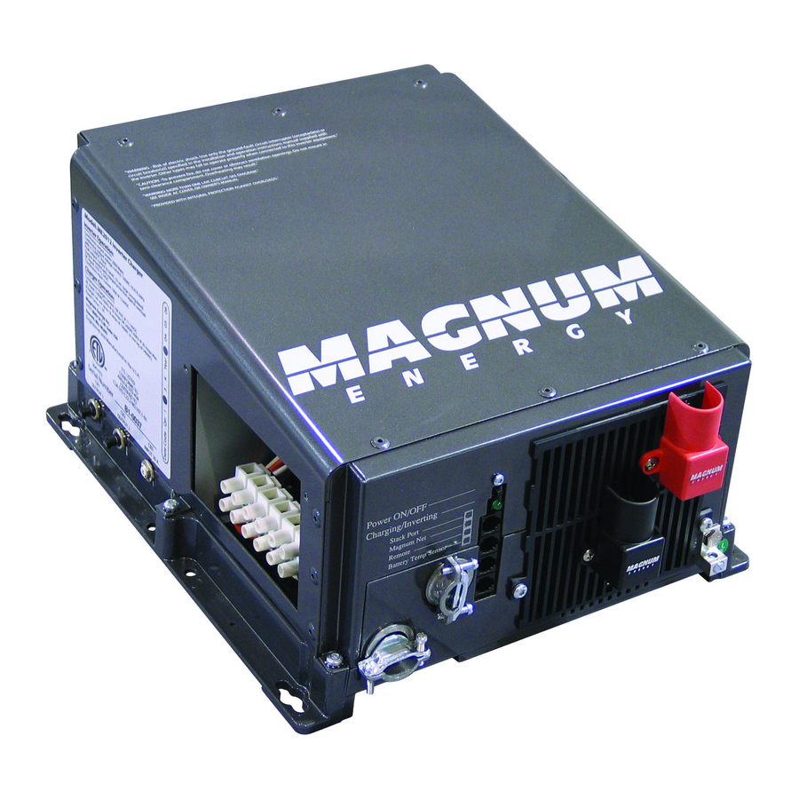
Magnum Energy ME Series Removal And Replacement
Inverter/charger dc terminal plate
Hide thumbs
Also See for ME Series:
- Operator's manual (77 pages) ,
- Owner's manual (62 pages) ,
- Operator's manual (44 pages)
Advertisement
Quick Links
Service Instructions: 64-1002
1.0 Description
These instructions provide information on removing and
replacing the DC terminal plate in a ME, MS or RD Series
inverter/charger. This is required when some internal
components are replaced or when the DC terminal plate
has been damaged and needs to be replaced with a new
DC terminal plate (kit part number: TDC-Plate).
Note: This document is part of a series of Service
Instructions to help qualified personnel replace
components that have failed or been damaged.
2.0 Installation Preparation
Before removing or replacing the DC terminal plate, read
this entire document carefully and follow all instructions.
2.1 Safety Precautions
Follow all electrical safety precautions and ESD
prevention guidelines below and in the
Precautions and ESD Prevention, Service Instructions:
64-1000.
Warning: Hazardous voltages are present within
the inverter when power is applied. Do not work
inside the inverter without first turning off and
disconnecting all AC and DC power to the inverter.
Warning: The capacitors inside the inverter store
electric energy even after all AC and DC power is
removed. After disconnecting all AC and DC power
to the inverter, short the positive and negative DC
terminals together to dissipate this energy.
Figure 1, DC Terminal Plate
© 2006 Magnum Energy, Inc.
(ME, MS or RD Series Inverter/Charger)
Electrical Safety
Page 1 of 2
Removal and Replacement
2.2 Included Materials
Before dismantling your inverter/charger, inspect the DC
terminal plate and confirm that there is no obvious
physical damage. Ensure the DC terminal plate kit
contains the items listed below; and if any item appears
to be damaged, missing or incorrect, contact Magnum
Energy.
•
DC terminal plate kit – includes an insulated plate
with positive and negative DC terminals, and two
5/16" nuts; as shown in figure 1.
Note: All removed items must be returned if
repair is for warranty consideration; save the
packing material and shipping container to use
when returning the removed items.
2.3 Required Tools and Equipment
Before disassembling the inverter, ensure you have the
following tools and equipment to remove and replace
the DC terminal plate:
•
T25 Torx head screwdriver (≥ 6" shaft recommended).–
for #10-32 screws.
7/16" socket with ≥ 6" extension and socket wrench
•
– for ¼-20 bolts.
7/16" open end wrench - for ¼-20 nuts (only needed
•
on inverters with the small FET board).
•
Torque wrench (130 in-lbs torque required) – for ¼-
20 bolts with 7/16" head.
3.0 Removing/Replacing the DC Plate
3.1 Removing the DC Terminal Plate
3.1.1
Remove the inverter's top cover and familiarize
yourself with the inverter's internal components as
described in the
Top Cover Removal and Replacement
with Internal Component Identification (ME, MS or RD
Series Inverter/Charger), Service Instructions:
3.1.2
Ensure all cables are removed from the positive
and negative terminals on the DC terminal plate.
3.1.3
Remove the two ¼-20 bolts (7/16" head) on
the back of the DC terminal plate (see figures 2 and 3).
Note: Record how this hardware is removed, it
will need to be reconnected in the same way.
Note: While unscrewing the ¼-20 bolts on buss-
wires, use a 7/16" wrench to hold the nut.
3.1.4
Remove the two #10-32 screws (T25 head)
holding the DC terminal plate to the front wall of the
inverter base (see figure 4, item B).
3.1.5
Remove the DC terminal plate by firmly lifting it
straight-up from the inverter base.
Service Instructions: 64-1002 (7/06)
DC Terminal Plate
64-1001.
Advertisement

Related Manuals for Magnum Energy ME Series


Summary of Contents for Magnum Energy ME Series
- Page 1 (see figure 4, item B). 3.1.5 Remove the DC terminal plate by firmly lifting it straight-up from the inverter base. Figure 1, DC Terminal Plate © 2006 Magnum Energy, Inc. Page 1 of 2 Service Instructions: 64-1002 (7/06)
- Page 2 Cover Removal and Replacement with Internal Component Identification (ME, MS or RD Series Inverter/Charger), Service Instructions: 64-1001. Figure 2, DC Terminal Plate to Small FET Board © 2006 Magnum Energy, Inc. Page 2 of 2 Service Instructions: 64-1002 (7/06)
Need help?
Do you have a question about the ME Series and is the answer not in the manual?
Questions and answers