Table of Contents
Advertisement
Quick Links
- 1 Fabric Interconnect Features
- 2 Cisco Ucs 6332 Fabric Interconnect
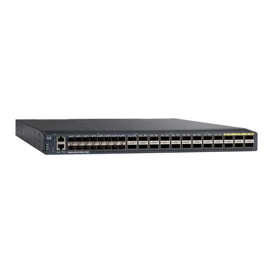
- 3 Cisco Ucs 6332-16Up Fabric Interconnect
- 4 Ports on the Cisco Ucs 6300 Fabric Interconnects
- 5 Power Supplies
- 6 Preparing for Network Connections
- 7 Connecting the Cisco Ucs 6300 Series Fabric Interconnect
- 8 Connecting to the Console Port
- Download this manual
Advertisement
Chapters
Table of Contents


Need help?
Do you have a question about the UCS 6332 and is the answer not in the manual?
Questions and answers